Sign In
Upload
Manuals
Brands
Agilent Technologies Manuals
Laboratory Equipment
7890 Series
Agilent Technologies 7890 Series Manuals
Manuals and User Guides for Agilent Technologies 7890 Series. We have
4
Agilent Technologies 7890 Series manuals available for free PDF download: Advanced Operation Manual, Troubleshooting Manual, Installation Checklist, Quick Reference Manual
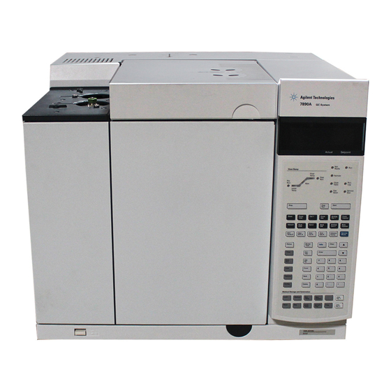
Agilent Technologies 7890 Series Advanced Operation Manual (246 pages)
Gas Chromatograph
Brand:
Agilent Technologies
| Category:
Laboratory Equipment
| Size: 4 MB
Table of Contents
Table of Contents
3
1 Programming
11
Programming
12
Run Time Programming
12
Using Run Time Events
12
Adding Events to the Run Table
13
Programming Run Time Events
13
The Run Table
13
Deleting Run Time Events
14
Editing Events in the Run Table
14
Clock Time Programming
15
Programming Clock Time Events
15
Using Clock Time Events
15
Adding Events to the Clock Table
16
Deleting Clock Time Events
16
Editing Clock Time Events
16
User-Key Programming
17
To Erase the Stored Keystrokes
17
To Play Back (Execute) the Stored Keystrokes
17
To Program a User Key
17
Post Run Programming
18
To Disable a Post Run Program
18
To Enable a Post Run Program
18
2 Flow and Pressure Modules
19
About Flow and Pressure Control
20
Maximum Operating Pressure
20
Pids
21
Inlet Modules
22
Detector Modules
23
Pressure Control Modules
24
Auxiliary Pressure Controllers
27
Restrictors
28
Examples
30
Using an aux EPC Channel to Supply Purge Gas to a Splitter
30
Using the PCM Channels
30
3 Inlets
33
Using Hydrogen
35
Inlet Overview
36
Carrier Gas Flow Rates
37
About Gas Saver
38
To Use Gas Saver
39
Pre Run and Prep Run
40
The [Prep Run] Key
40
Auto Prep Run
41
About Heaters
42
About the Split/Splitless Inlet
44
Septum Tightening (S/SL)
44
Standard and High-Pressure Versions of the S/SL Inlet
44
Split/Splitless Inlet Split Mode Overview
45
Split/Splitless Inlet Splitless Mode Overview
46
The S/SL Inlet Pulsed Split and Splitless Modes
47
Split/Splitless Inlet Split Mode Minimum Operating Pressures
48
Selecting the Correct S/SL Inlet Liner
49
Setting Parameters for the S/SL Split Mode
51
Vapor Volume Calculator
51
Selecting Parameters for the S/SL Splitless Mode
52
Setting Parameters for the S/SL Splitless Mode
53
Setting Parameters for the S/SL Pulsed Modes
54
About the Multimode Inlet
55
Septum Tightening (MMI)
55
Cooling the MMI
56
Heating the MMI
56
MMI Split Mode Minimum Operating Pressures
57
Selecting the Correct MMI Liner
58
MMI Split and Pulsed Split Modes
60
Vapor Volume Calculator
60
MMI Splitless and Pulsed Splitless Modes
64
MMI Solvent Vent Mode
70
MMI Direct Mode
78
To Develop a MMI Method that Uses Large Volume Injection
79
Multiple Injections with the MMI
82
About the Packed Column Inlet
88
Setting Parameters
90
About the Cool On-Column Inlet
92
COC Inlet Temperature Control
93
Retention Gaps
93
Setup Modes of the COC Inlet
93
Setting COC Inlet Flows/Pressures
94
Setting COC Inlet Parameters
95
About the PTV Inlet
96
PTV Sampling Heads
96
Heating the PTV Inlet
97
Cooling the PTV Inlet
98
PTV Inlet Split and Pulsed Split Modes
98
PTV Inlet Splitless and Pulsed Splitless Modes
102
PTV Inlet Solvent Vent Mode
109
To Develop a PTV Method that Uses Large Volume Injection
117
Multiple Injections with the PTV Inlet
120
About the Volatiles Interface
126
VI Operating Modes
127
About the VI Split Mode
128
About the VI Splitless Mode
132
About the VI Direct Mode
137
Preparing the Interface for Direct Sample Introduction
140
VI Direct Mode Initial Values
142
VI Direct Mode Setpoint Dependencies
142
Setting Parameters for the VI Direct Mode
143
4 Columns and Oven
145
Columns and Oven
146
About the Oven
146
Oven Safety
146
Configuring the Oven
147
Cryogenic Operation
148
Cryogenic Setpoints
148
About Oven Temperature Programming
150
Programming Setpoints
150
Oven Ramp Rates
151
Setting the Oven Parameters for Constant Temperature
152
Setting the Oven Parameters for Ramped Temperature
152
About the Oven Insert
154
About Columns
155
About the Column Modes
155
Selecting the Correct Packed Glass Column Type
155
Select a Column Mode
156
Enter a Flow or Pressure Program (Optional)
157
Setting the Column Parameters for Constant Flow or Constant Pressure
157
Programming Column Pressure or Flow
158
Backflushing a Column
159
Backflushing Using a Capillary Flow Technology Device
160
Backflushing When Connected to an MSD
160
Nickel Catalyst Tube
165
About the Nickel Catalyst Tube
165
Nickel Catalyst Gas Flows
165
Setting Temperatures for the Nickel Catalyst Tube
166
Detectors
167
About Makeup Gas
168
About the FID
169
How FID Units Are Displayed in Agilent Data Systems and on the GC
170
FID Automatic Reignition (Lit Offset)
171
To Extinguish the FID Flame
171
To Light the FID Flame
171
Recommended Starting Conditions for New FID Methods
172
Setting Parameters for FID
173
About the TCD
174
TCD Carrier, Reference, and Makeup Gas
176
TCD Pneumatics
176
TCD Gas Pressures
177
Chemically Active Compounds Reduce TCD Filament Life
178
Selecting Reference and Makeup Flows for the TCD
178
Changing the TCD Polarity During a Run
179
Detecting Hydrogen with the TCD Using Helium Carrier Gas
179
Setting Parameters for the TCD
180
About the Uecd
182
Uecd Safety and Regulatory Information
182
Uecd Warnings
183
Safety Precautions When Handling Uecds
184
Uecd Detector Gas
185
Uecd Gas Flows
185
Uecd Linearity
185
Uecd Temperature
185
Recommended Starting Conditions for New Uecd Methods
186
Uecd Analog Output
186
Uecd Makeup Gas Notes
186
Setting Parameters for the Uecd
187
Uecd Temperature Programming
187
About the NPD
188
New NPD Features and Changes
188
NPD Flows and General Information
188
NPD Software Requirements
188
NPD Flow, Temperature, and Bead Recommendations
189
NPD Required Gas Purity
191
Setting Parameters for the NPD
192
Selecting an NPD Bead Type
193
Changing from a Ceramic Bead to a Blos Bead
194
Selecting an NPD Jet
194
To Configure the NPD
195
Automatically Adjusting NPD Bead Voltage
196
Aborting NPD Adjust Offset
197
Extending the NPD Bead Life
197
Setting NPD Adjust Offset on the Clock Table
197
Setting the Initial Bead Voltage for New Beads
198
Setting NPD Bead Voltage Manually (Optional)
199
About the FPD
200
FPD + Linearity
201
FPD + Lit Offset
201
FPD + Optical Filters
201
FPD + Photomultiplier Protection
201
Inlet Liners for Use with the FPD
201
FPD + Gas Flows
202
FPD + Gas Purity
202
FPD + Temperature Considerations
202
Lighting the FPD + Flame
203
Setting Parameters for the FPD
204
About the FPD
206
FPD Linearity
207
FPD Lit Offset
207
FPD Optical Filters
207
FPD Photomultiplier Protection
207
Starting up and Shutting down the FPD
207
FPD Gas Flows
208
FPD Gas Purity
208
FPD Temperature Considerations
208
Inlet Liners for Use with the FPD
208
Lighting the FPD Flame
209
Setting Parameters for the FPD
210
6 Valves
213
About Valves
214
The Valve Box
215
Heating the Valves
215
Valve Temperature Programming
216
Configuring an aux Thermal Zone
216
Valve Control
217
The Valve Drivers
217
The Internal Valve Drivers
217
The External Valve Drivers
218
Valve Types
219
Configuring a Valve
220
Controlling a Valve
221
From the Keyboard
221
From the Run or Clock Time Tables
221
Simple Valve: Column Selection
221
Gas Sampling Valve
222
Multiposition Stream Selection Valve with Sampling Valve
223
7 Gc Output Signals
225
About Signals
226
Signal Types
227
Value
227
Analog Signals
229
Analog Zero
229
Analog Range
229
Analog Data Rates
230
Selecting Fast Peaks (Analog Output)
231
Digital Signals
232
Digital Zero
232
Signal Freeze and Resume
232
Data Rates with Agilent Data Systems
233
Zero Init Data Files
235
Column Compensation
236
Creating a Column Compensation Profile
237
Making a Run Using Analog Output Column Compensation
237
Plotting a Stored Column Compensation Profile
238
Test Plot
239
Auxiliary Devices
242
About Auxiliary Pressure Control
242
About aux Thermal Zone Control
243
About Cryo Trap Control
243
About Auxiliary Device Contacts
244
About the 24V Auxiliary Device Power Supply
244
About Auxiliary Columns
244
About Auxiliary Detectors
245
Advertisement
Agilent Technologies 7890 Series Troubleshooting Manual (208 pages)
Gas Chromatograph
Brand:
Agilent Technologies
| Category:
Laboratory Equipment
| Size: 5.34 MB
Table of Contents
Table of Contents
3
1 Concepts and General Tasks
10
Concepts
10
How to Troubleshoot Using this Manual
10
The [Status] Key
10
Error Conditions
11
Systems Configured for Enhanced Communications
12
Configurable Items to Always Keep Current
13
Inlet and Detector Configuration
13
Column Configuration
13
Automatic Liquid Sampler Configuration
14
Gas Configuration
14
To View the Run Log, Maintenance Log, and Event Log
15
Run Log
15
Maintenance Log
15
Event Log
15
Information to Obtain before Calling Agilent for Service
16
2 ALS and Detector Symptoms
17
Plunger Errors
18
Procedure
18
Vial Mishandled by als (7693A)
19
Alignment Light on 7693A/7650A Injector Tower Is on
21
Vial Mishandled by als (7683)
22
Alignment Light on 7683B Injector Tower Is on
24
Syringe Needle Bends During Injection into Inlet
25
FID Fails Leakage Current Test
26
Possible Causes
26
Procedure
26
NPD Fails Leakage Current Test
27
FID Fails Baseline Test
28
To Resolve Low Sensitivity with an FID
29
FID Does Not Ignite
30
FID Ignitor Does Not Glow During Ignition Sequence
31
Corrosion in FID Collector and Ignitor Glow Plug
33
FPD Does Not Ignite
34
NPD Adjust Offset Process Fails
36
NPD Bead will Not Ignite
37
FPD + Temperature will Not Become Ready
38
Blinking Not Ready Light: Detector Hardware Fault/Tcd Filament Voltage
39
Shutdown (Defective) Device
40
3 Chromatographic Symptoms
41
Retention Times Not Repeatable
42
Peak Areas Not Repeatable
43
Contamination or Carryover
44
Isolate the Source
44
Check Possible Causes-All Inlet and Detector Combinations
44
Larger Peaks than Expected
47
Peaks Not Displayed/No Peaks
48
Baseline Rise During Oven Temperature Program
50
Poor Peak Resolution
51
Peak Tailing
52
NPD Peak Tailing
53
Peak Boiling Point or Molecular Weight Discrimination Poor
54
For any Inlet Operating in Split Mode with any Detector
54
For any Inlet Operating in Splitless Mode with any Detector
54
Sample Decomposition in Inlet/Missing Peaks
55
Peak Fronting
56
Noisy Detector, Including Wander, Drift, and Baseline Spikes
57
Noisy Baseline
57
Baseline Wander and Drift
59
Baseline Spiking
60
Microcell Electron Capture Detector (Uecd) Noise and Sensitivity
63
Display Signal Evaluation
63
Sensitivity
65
Contamination (High Baseline)
66
Low Peak Area or Height (Low Sensitivity)
67
To Resolve Low Sensitivity with an FID
68
FID Flame Goes out During a Run and Attempts to Reignite
70
FID Baseline Output above 20 Pa
72
FID Baseline Output at Maximum (~8 Million)
73
FPD Flame Goes out During a Run and Attempts to Reignite
74
FPD Quenching/Repeatability
75
FPD Output too High or too Low
76
FPD Low Peak Areas
77
FPD Large Peak Width at Half-Height
78
FPD Baseline Output High, > 20 Pa
79
NPD Solvent Quenching
80
NPD Response Low
81
NPD Baseline Output > 8 Million
83
NPD Adjust Offset Process Not Functioning Properly
84
NPD Low Selectivity
85
Negative Peaks Seen with TCD
86
TCD Baseline Has Dampened Sinusoidal Noise Trailing Peaks (Ringing Baseline)
87
TCD Peaks Have Negative Dip on Tail
88
4 GC Not Ready Symptoms
89
GC Never Becomes Ready
90
Flow Never Becomes Ready
91
Oven Temperature Never Cools Down/Cools very Slowly
92
Oven Never Heats up
93
Temperature Never Becomes Ready
94
Cannot Set a Flow or Pressure
95
A Gas Does Not Reach Setpoint Pressure or Flow
96
A Gas Exceeds Pressure Setpoint or Flow
97
The Inlet Pressure or Flow Fluctuates
98
Cannot Maintain a Pressure as Low as the Setpoint on a Split Inlet
99
The Measured Column Flow Does Not Equal the Displayed Flow
100
FID Does Not Ignite
101
FID Ignitor Does Not Glow During Injection Sequence
102
FID or NPD Measured Hydrogen and Makeup Gas Flows Much Less than Setpoint
104
NPD Adjust Offset Process Fails
105
FPD Does Not Ignite
106
Valve Not Ready
108
External Valves
108
Gas Sampling Valves
108
Multiposition Valve
108
Blinking Not Ready Light: Detector Hardware Fault/Tcd Filament Voltage
109
5 Shutdown Symptoms
112
Column Shutdowns
112
Hydrogen Shutdowns
114
Hydrogen Used in Inlets and Auxiliary Gas Streams
114
Hydrogen Sensor
115
Detector Air Shutdowns
116
7890B MS Shutdown
117
Clearing an MS Shutdown
118
After Resolving an MS Shutdown
118
Thermal Shutdowns
119
6 GC Power on and Communication Symptoms
122
GC Does Not Turn on
122
PC Cannot Communicate with GC
123
GC Cannot Communicate with a Configured MS or HS
124
GC Does Not Recover after Firmware Update
125
GC Turns On, then Stops During Startup (During Self-Test)
126
7 Checking for Leaks
127
Leak Check Tips
128
To Check for External Leaks
129
To Check for GC Leaks
131
Leaks in Capillary Flow Fittings
132
To Perform an Inlet Leak Check
133
To Set Warning Limits for a Leak Check
135
To Disable a Warning Limit for the Inlet Leak Check
135
To Check for Leaks in a Split/Splitless Inlet
136
Cannot Reach Pressure Setpoint
136
Low Sensitivity or Poor Repeatability
137
To Perform a SS Pressure Decay Leak Test
138
To Perform a SS Inlet Pressure Decay Test at the GC Keyboard
138
To Correct Leaks in the Split Splitless Inlet
143
To Check for Leaks in a Multimode Inlet
144
Cannot Reach Pressure Setpoint
144
Low Sensitivity or Poor Repeatability
145
To Perform a MMI Pressure Decay Test
146
To Perform a Multimode Inlet Pressure Decay Test
146
To Correct Leaks in the Multimode Inlet
150
To Perform a PP Pressure Decay Leak Test
151
To Perform a PP Inlet Pressure Decay Test
151
To Correct Leaks in the Packed Column Inlet
155
To Perform a COC Pressure Decay Leak Test
156
To Perform a COC Pressure Decay Test
156
To Correct Leaks in the Cool On-Column Inlet
160
To Perform a PTV Pressure Decay Test
161
To Correct Leaks in the PTV Inlet
165
To Perform a VI Pressure Decay Test
166
To Prepare the VI for a Closed System Leak Check
170
To Correct Leaks in the Volatiles Interface
171
8 Troubleshooting Tasks
174
To Measure a Column Flow
174
Measuring FID, TCD, Uecd, and FPD Column Flow
174
Measuring NPD Column Flow
176
To Measure a Split Vent or Septum Purge Flow
178
To Measure a Detector Flow
180
Measuring FID, TCD, Uecd, and FPD Flows
180
Measuring NPD Flows
183
To Perform the GC Self-Test
185
To Check or Monitor Split Vent Line Backpressure
186
To Set a Warning Limit for the Inlet Trap Check
186
To Disable a Warning Limit for the Inlet Trap Check
188
To Run the Inlet Trap Check
189
To Perform a SS Split Vent Restriction Test
191
To Check a Split Vent Line for Contamination
192
To Adjust the FID Lit Offset
194
To Verify that the FID Flame Is Lit
195
To Verify FID Ignitor Function During Ignition Sequence
196
To Measure FID Leakage Current
197
To Measure FID Baseline Output
198
To Isolate the Cause of FID Noise
199
To Measure NPD Leakage Current
200
To Check for a Plugged FID Jet
201
To Check for a Plugged NPD Jet
202
To Verify that the NPD Bead Is Ignited
203
To Verify that the FPD Flame Is Lit
204
To Adjust the FPD Lit Offset
205
When to Change Gas Purifiers
206
To Ignore a Device's Readiness State
207
To Use the Stopwatch
208
Agilent Technologies 7890 Series Installation Checklist (8 pages)
Brand:
Agilent Technologies
| Category:
Measuring Instruments
| Size: 0.15 MB
Advertisement
Agilent Technologies 7890 Series Quick Reference Manual (4 pages)
GC Heated Zones
Brand:
Agilent Technologies
| Category:
Laboratory Equipment
| Size: 0.46 MB
Advertisement
Related Products
Agilent Technologies 7890B
Agilent Technologies 7890A
Agilent 7820 MSD
Agilent Technologies 7820 VL MSD
Agilent Technologies 7890A GC
Agilent Technologies 7683
Agilent Technologies 7000 Triple Quadrupole
Agilent Technologies 7200
Agilent Technologies agilent 7683B
Agilent Technologies 710 Series
Agilent Technologies Categories
Measuring Instruments
Laboratory Equipment
Test Equipment
Water Pump
Power Supply
More Agilent Technologies Manuals
Login
Sign In
OR
Sign in with Facebook
Sign in with Google
Upload manual
Upload from disk
Upload from URL