Sign In
Upload
Manuals
Brands
Agilent Technologies Manuals
Measuring Instruments
4349B
Agilent Technologies 4349B Manuals
Manuals and User Guides for Agilent Technologies 4349B. We have
3
Agilent Technologies 4349B manuals available for free PDF download: Manual, Service Manual, Technical Overview
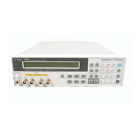
Agilent Technologies 4349B Manual (233 pages)
4-Channel High Resistance Meter
Brand:
Agilent Technologies
| Category:
Measuring Instruments
| Size: 1.96 MB
Table of Contents
Section 1
21
Table of Contents
21
Section 2
27
Getting Started
33
Introduction
33
Features
34
Overview
34
Accessories Available
35
Options Available
35
Front Panel
36
Display
38
Rear Panel
39
Initial Inspection
40
Instruction for Cleaning
40
Providing Clearance to Dissipate Heat at Installation Site
40
Power Cable
41
Fuse
43
Power Requirements
43
Preparation for Use
43
Turning on the 4349B
44
Direct Execution Keys
45
Selection Keys
45
Toggle Keys
45
Using Front Panel Keys
45
Numeric Keys
46
Value Setup Keys
46
Back Space Key
47
Left/Down and Right/Up Arrow Keys
47
Maximum and Minimum Keys
47
If You Have any Problems
48
Operating the 4349B Introduction
49
16117E Test Lead
50
External Voltage Source
50
Speci Cations
50
Test Leads
50
Installation
51
Typical Measurement System
51
Measurement con Guration
53
To Perform the OPEN Correction Function
53
To Reset the 4349B
53
To Select a Measurement Parameter
53
To Enter the Voltage Value
54
To Select the Channel
54
To Select the Measurement Range
54
To Select the Measurement Time Mode
55
To Set the Averaging Rate
55
To Set the Trigger Delay Time
55
To Set the Contact Check
56
Reading the Limit Data of Contact Check Function
57
Reading the Capacitance Data at DUT Measurement
58
To Set the Beeper Mode
58
Saving and Recalling Instrument Settings
59
Making a Measurement
60
To Use the Comparator Function
60
Triggering a Measurement
60
To Change the Measurement Settings Display
62
To Select the Display Mode and Display Digits
62
Locking out the Front Panel Keys
63
Printing Measurement Data
63
Selecting Local Mode
63
Setting the GPIB Address
63
Performing a Self-Test
64
Testing the Front Panel Keys' Functionality
64
To Test the 4349B
64
If an Error Message Is Displayed
65
If the 4349B Does Not Accept any Key Input
65
If the Display Is Blank and the 4349B Appears Dead
65
If the Resistance Value Is Always 0
65
If Your 4349B Has a Problem
65
Function Reference Introduction
67
Display
68
Front Panel
68
Chassis Terminal
69
INPUT (Ch1, Ch2, Ch3, and Ch4) Terminals
69
LINE Switch
69
Average Key
70
Channel Key
70
Measurement Parameter Key
70
Measurement Time Key
70
Show Setting Key
70
Voltage Entry Key
70
Auto/Hold Range Key
71
Comparator Limit Key
71
Display Mode Key
71
Range Setup Key
71
Address Key
72
Local Key
72
Trigger Key
72
Trigger Mode Key
72
BLUE Shift Key
73
Delay Key
73
Recall Key
73
Right/Up Arrow Key and Left/Down Arrow Key
73
Save Key
73
Back Space Key
74
Comparator Key
74
Enter Key
74
Exponential Key
74
Maximum Key
74
Minimum Key
74
Contact Check Key
75
Key Lock Key
75
Open Key
75
Reset Key
76
Reset Settings
76
Con Guration Key
77
External Trigger
78
Rear Panel
78
LINE Fuse Holder
79
Line Voltage Selection
79
LINE Voltage Selector
79
Power Cord
79
Power Cord Receptacle
79
Serial Number Plate
79
Handler Interface
80
Speci Cations
80
Timing Diagram
83
GPIB Interface
84
Overall Measurement Theory
85
Theory of Operation
85
Overall Block Diagram
86
Contact Check Feature
87
Remote Operation Introduction
89
Getting Started
90
Input/Output Statements
90
Reading the GPIB Address
90
Sending a Remote Command
90
Getting Data from the 4349B
91
Query Commands
91
Returning to Local Mode
91
To Control the 4349B from an External Computer
92
To Perform the OPEN Correction
93
To Reset the 4349B
93
To Select the Measurement Parameter
93
To Set the LINE Frequency
93
To Set up the 4349B
93
To Enter Voltage Value
94
To Select the Measurement Range
94
To Set the Measurement Time Mode
94
To Lock out the Front Panel Keys
95
To Perform the Contact Check
95
To Set the Averaging Rate
95
To Set the Beeper Mode
95
To Set the Trigger Delay Time
95
To Use the Comparator Function
96
To Wait until Previously Sent Commands Are Completed
96
To Get the Current Instrument Settings
97
To Save and Recall Instrument Settings
97
To Trigger a Measurement
98
To Retrieve Data ECiently
100
To Transfer Data Using the Real Data Format
100
To Use Data Bu er
100
Other Features
101
To Report the Instrument's Status
101
To Test the 4349B
101
If You Have a Problem
103
Common Commands
105
GPIB Commands
105
GPIB Reference Introduction
105
Subsystem Commands
105
Subsystem Command Tree
108
Case
109
Common Command Syntax
109
Parameters
109
Program Message Syntax
109
Program Message Terminator
109
Subsystem Command Syntax
109
Parameter Types
110
Multiple Messages
111
Query and Response Message Syntax
111
SuX
111
SuX Multiplier
111
Command Reference
112
Notations
112
Abort
113
Abort Command
113
Calculate
114
Calculate 1 2 3
114
Calculate Subsystem
114
Calculate :Limit:clear
115
Calculate :Limit:fail
115
Limit:lower:state
115
Limit:lower[:Data] < Numeric Value
115
Limit:state
115
Limit:upper:state
116
Limit:upper[:Data] < Numeric Value
116
ON J off
116
Data[:Data]? Dbuf
117
Status Reporting Structure
137
Status Byte Register
138
Standard Event Status Register
139
Standard Event Status Register Assignments
139
Standard Operation Status Group Structure
140
Operation Status Register Assignments
141
Questionable Status Register Assignments
141
NR1 Format
144
NR2 Format
144
NR3 Format
144
Real Data Format
145
High Throughput Measurement System
148
High Throughput Measurement Sample Program
150
Multi Test Voltage Measurement System
151
Multi Test Voltage Measurement Sample Program
153
Additional Error Due to Voltage Source Noise
156
Precharge Time
158
Wait Time
159
Absorption Phenomena
161
Insulation Resistance Measurement
161
Measurement Basics Introduction
161
Residual Charge E Ect
161
Voltage CoeCient and Temperature CoeCient
161
Shielding
162
General Information Introduction
163
Measurement Conditions
164
Measurement Parameters
164
Speci Cations
164
Measurement Accuracy
165
Measurement Range
165
Measurement Support Functions
167
General
168
Measurement Accuracy
169
Supplemental Performance Characteristics
169
Typical Measurement Accuracy
169
Measurable Capacitance Range
170
Measurable Current Range and Measurable Capacitance Range
170
Additional Error Due to the Voltage Source Noise
171
Current Measurement Additional Error (Measurement Time:10 Msec)
171
Current Measurement Additional Error (Measurement Time:100 Msec)
172
Current Measurement Additional Error (Measurement Time:30 Msec)
172
Current Measurement Additional Error (Measurement Time:400 Msec)
173
Additional Error Reduction by Connecting a Series Resistor
174
Consumption Memory Duration
177
Measurement Time
177
And Cable Capacitance Cig
178
Contact Check E Ective Range
178
Relation between C
178
Maintenance Introduction
179
Test Equipment
179
Calculation Sheet
180
Calibration Cycle
180
Introduction
180
Performance Test Record
180
Performance Tests
180
Test Equipment
180
Ammeter O Set Voltage and Input Resistance Test
181
Ammeter O Set Voltage Test
181
Ammeter O Set Voltage Test Setup
181
Procedure
181
Speci Cations
181
Test Equipment
181
Ammeter Input Resistance Test
182
Ammeter Input Resistance Test Setup Using DC Power Supply
182
Current Measurement Accuracy Test
184
Procedure
184
Speci Cation
184
Test Equipment
184
Current Measurement Accuracy Test Setup Using DC Power Supply
185
Current Measurement Accuracy Test Setup Using DC Voltage Calibrator
185
Current Measurement Accuracy Test Settings
186
Procedure
187
Resistance Measurement Accuracy Test
187
Resistance Measurement Accuracy Test Setup
187
Speci Cation
187
Test Equipment
187
Resistance Measurement Accuracy Test Setup Using DC Power Supply
188
Resistance Measurement Accuracy Test Setup Using DC Voltage Calibrator
188
Resistance Measurement Accuracy Test Settings
189
Ammeter Input Resistance Test (Channel 1)
190
Ammeter Input Resistance Test (Channel 2)
190
Ammeter Input Resistance Test (Channel 3)
190
Ammeter Input Resistance Test (Channel 4)
190
Calculation Sheet
190
RC Box Calibration Values
190
Current Measurement Accuracy Test (Channel 1)
191
Current Measurement Accuracy Test (Channel 2)
191
Current Measurement Accuracy Test (Channel 3)
192
Current Measurement Accuracy Test (Channel 4)
192
Resistance Measurement Accuracy Test (Channel 1)
193
Resistance Measurement Accuracy Test (Channel 2)
193
Resistance Measurement Accuracy Test (Channel 3)
194
Resistance Measurement Accuracy Test (Channel 4)
194
Performance Test Record
195
Ammeter O Set Voltage and Input Resistance Test (Channel 1)
196
Current Measurement Accuracy Test (Channel 1)
196
Resistance Measurement Accuracy Test (Channel 1)
196
Ammeter O Set Voltage and Input Resistance Test (Channel 2)
197
Current Measurement Accuracy Test (Channel 2)
197
Resistance Measurement Accuracy Test (Channel 2)
197
Ammeter O Set Voltage and Input Resistance Test (Channel 3)
198
Current Measurement Accuracy Test (Channel 3)
198
Resistance Measurement Accuracy Test (Channel 3)
198
Ammeter O Set Voltage and Input Resistance Test (Channel 4)
199
Current Measurement Accuracy Test (Channel 4)
199
Resistance Measurement Accuracy Test (Channel 4)
199
Functional Test
200
Introduction
200
Test Equipment
200
External Trigger Function Test
201
Handler Interface Functional Test
201
Handler Interface Functional Test Setup
201
Initial Setup
201
Key Lock Function Test
201
Procedure
201
Test Equipment
201
Handler Interface Output Order
202
Handler Interface Output Test
202
Contact Check Functional Test
203
Contact Check Functional Test Setup
203
Procedure
203
Test Equipment
203
Manual Changes
205
Manual Changes Introduction
205
Serial Number
206
Change 1
207
Electrical Characteristics
209
Handler Interface Installation Introduction
209
Output Signals
209
Input Signals
211
Procedure
213
Setting up the Handler Interface Board
213
Tools and Fasteners
213
Advertisement
Agilent Technologies 4349B Service Manual (63 pages)
4-Channel High Resistance Meter
Brand:
Agilent Technologies
| Category:
Measuring Instruments
| Size: 1.26 MB
Table of Contents
Table of Contents
10
General Information
14
Introduction
14
Instruments Covered by this Manual
14
Required Equipment
15
Required Language Extensions
15
Adjustments Introduction
16
Safety Consideration
16
Required Equipment
16
Adjustment Tools
17
Adjustable Components
17
Factory-Selected Components
17
EEPROM Write Protect Switch
17
Related Adjustments
17
Adjustment Program
18
Adjustment Program Flow
18
Program Installation
19
Making a Working Copy
19
De Ning the con Guration
19
Program Execution
20
Adjustments Procedure References
21
DC Voltage Source (DC Power Supply or DCV Calibrator)
21
Channel 1 Adjustment
22
Channel 1 Adjustment Using DC Power Supply
22
Equipment
22
Setup 1/2
23
Channel 1 Adjustment, Setup 1/2 (Using DC Power Supply)
23
Setup 2/2
24
Channel 1 Adjustment, Setup 2/2 (Using DC Power Supply)
24
Channel 1 Adjustment Using DCV Calibrator
25
Equipment
25
Setup 1/2
25
Channel 1 Adjustment, Setup 1/2 (Using DCV Calibrator)
25
Setup 2/2
26
Channel 2, 3, and 4 Adjustments
26
Channel 1 Adjustment, Setup 2/2 (Using DCV Calibrator)
26
Assembly Replacement Introduction
28
Ordering Information
28
Restored Exchange Assemblies
28
Replacing the A2 CPU Board Assembly
29
Replaceable Assembly List
29
A2 CPU Board Assembly, Replaceable Assembly List
31
Replaceable Assembly List
31
Replaceable Mechanical Parts List
32
Replaceable Mechanical Parts List
33
Replaceable Mechanical Parts List
34
Replaceable Mechanical Parts List
35
Disassembly Procedures
36
Tools and Fasteners
36
Cover Removal
36
A1 Main Board Removal
37
Removal Procedure
37
A2 CPU Board Assembly Removal
37
A5 AC Inlet Board Assembly Removal
37
Keyboard Assembly Removal
37
LCD Assembly Removal
38
Removal Procedure
38
Triaxial Connector Removal
39
Removal Procedure
39
Troubleshooting Introduction
40
Safety Considerations
40
Required Equipment
40
After Service Product Safety Checks
41
Theory of Operation
42
Overall Measurement Theory
42
Ohm's Law
42
Overall Block Diagram
43
Analog Section
43
I-V Converter
45
I-V Converter Block Diagram
45
Digital Section
46
Digital Section Block Diagram
46
Power Supply Section
47
Power Supply Section Block Diagram
47
Troubleshooting
48
Troubleshooting Flow
49
Check Procedure References
50
Check 1, DC-DC Converter Output Voltage
50
DC-DC Converter Output Voltage Check
50
DC-DC Converter Output Voltages (Connected)
50
Check 2, LCD Displays Anything
51
Check 3, LCD Operates Correctly
51
Check 4, any Error Message on LCD
51
Check 5, CPU Related Error Message
51
Check 6, CPU Power LED Lights
51
Check 7, any Error Code on LED
52
Check 8, CPU Fuse High Lead Voltage
53
Check 9, Fuse and Line Switch
53
Check 10, DC-DC Converter Input Voltage
54
Check 11, DC-DC Converter Open Output Voltages
55
DC-DC Converter Output Connector
55
DC-DC Converter Open Output Voltages
55
Check 12, Transformer Secondary Voltage
56
Manual Changes
58
Default Jumper and Switch Settings
60
Jumper and Switch Settings
60
Index
62
Agilent Technologies 4349B Technical Overview (9 pages)
High Resistance Meters
Brand:
Agilent Technologies
| Category:
Measuring Instruments
| Size: 0.71 MB
Advertisement
Advertisement
Related Products
Agilent Technologies Agilent 4396B
Agilent Technologies 437B
Agilent Technologies 4395A
Agilent Technologies 4339B
Agilent Technologies 4352B
Agilent Technologies 4338B
Agilent Technologies 4284A
Agilent Technologies 490
Agilent Technologies 4200 FlexScan
Agilent Technologies 4286A
Agilent Technologies Categories
Measuring Instruments
Laboratory Equipment
Test Equipment
Water Pump
Power Supply
More Agilent Technologies Manuals
Login
Sign In
OR
Sign in with Facebook
Sign in with Google
Upload manual
Upload from disk
Upload from URL