Kyocera KM-3050 Service Manual
Laser printers
Hide thumbs
Also See for KM-3050:
- Service manual (252 pages) ,
- Specifications (1 page) ,
- Command reference manual (410 pages)

Related Manuals for Kyocera KM-3050


Summary of Contents for Kyocera KM-3050
-
Page 1: Service Manual
KM-3050 KM-4050 KM-5050 SERVICE MANUAL Published in April 2008 842GN119 2GNSM069 Rev. 9... - Page 2 CAUTION RISK OF EXPLOSION IF BATTERY IS REPLACED BY AN INCORRECT TYPE. DISPOSE OF USED BATTERIES ACCORDING TO THE INSTRUCTIONS. It may be illegal to dispose of this battery into the municipal waste stream. Check with your local solid waste officials for details in your area for proper disposal. ATTENTION IL Y A UN RISQUE D’EXPLOSION SI LA BATTERIE EST REMPLACEE PAR UN MODELE DE TYPE INCORRECT.
-
Page 3: Revision History
Revision history Revision Date Replaced pages Remarks November 10, 2006 CONTENTS, 1-1-1 to 1-1-3, 1-1-5, 1-2-2, 1-2-4 to 6, 1-2-9 to 1-2-12, 1-3-5 to 1-3-102, 1-4-1, 1-4-2, 1-4-6, 1-4-7, 1-4-22, 1-4-25, 1-4-28, 1-4-31, 1-4-32, 1-4-35 to 37, 1-4-57 to 60, 1-5-4 to 8, 1-5-16, 1-5-19, 1-5-23, 1-5-25 to 1-5-40, 1-6-1 to 1-6-4, 2-1-1, 2-1-4, 2-1-10, 2-1-13, 2-1-15, 2-2-4, 2-2-6, 2-3-1, 2-3-2, 2-3-8, 2-3-11, 2-3-13 to 2-3-16, 2-4-1 to 2-4-6... - Page 4 This page is intentionally left blank.
-
Page 5: Safety Precautions
Safety precautions This booklet provides safety warnings and precautions for our service personnel to ensure the safety of their customers, their machines as well as themselves during maintenance activities. Service personnel are advised to read this booklet carefully to familiarize themselves with the warnings and precautions described here before engaging in maintenance activities. - Page 6 Safety warnings and precautions Various symbols are used to protect our service personnel and customers from physical danger and to prevent damage to their property. These symbols are described below: DANGER: High risk of serious bodily injury or death may result from insufficient attention to or incorrect compliance with warning messages using this symbol.
-
Page 7: Installation Precautions
1.Installation Precautions WARNING • Do not use a power supply with a voltage other than that specified. Avoid multiple connections to one outlet: they may cause fire or electric shock. When using an extension cable, always check that it is adequate for the rated current....................•... -
Page 8: Precautions For Maintenance
2.Precautions for Maintenance WARNING • Always remove the power plug from the wall outlet before starting machine disassembly....• Always follow the procedures for maintenance described in the service manual and other related brochures............................• Under no circumstances attempt to bypass or disable safety features including safety mechanisms and protective circuits. - Page 9 • Do not remove the ozone filter, if any, from the copier except for routine replacement..... • Do not pull on the AC power cord or connector wires on high-voltage components when removing them; always hold the plug itself...................... •...
- Page 10 This page is intentionally left blank.
- Page 11 2GN/2GP/2GR-8 CONTENTS 1-1 Specifications 1-1-1 Specifications............................1-1-1 1-1-2 Parts names............................1-1-4 (1) Machine.............................1-1-4 (2) Operation panel..........................1-1-5 1-1-3 Machine cross section ..........................1-1-6 1-2 Installation 1-2-1 Installation environment .........................1-2-1 1-2-2 Unpacking and installation ........................1-2-2 (1) Installation procedure ........................1-2-2 (2) Setting initial copy modes........................1-2-10 1-2-3 Installing the key counter (option) ......................1-2-11 1-2-4 Installing the expanded memory (option)....................1-2-13 1-3 Maintenance Mode 1-3-1 Maintenance mode ..........................1-3-1...
-
Page 12: Table Of Contents
(1) Precautions ............................1-5-1 (2) Drum..............................1-5-1 (3) Toner ..............................1-5-1 (4) How to tell a genuine Kyocera Mita toner container................1-5-2 1-5-2 Paper feed section ..........................1-5-3 (1) Detaching and refitting the forwarding, paper feed and separation pulleys ........1-5-3 (2) Detaching and refitting the MP separation, MP paper feed and MP forwarding pulleys ....1-5-5 (3) Detaching and refitting the left and right registration cleaner ............1-5-10... -
Page 13: Table Of Contents
2GN/2GP/2GR-8 2-1 Mechanical construction 2-1-1 Paper feed section ..........................2-1-1 2-1-2 Main charging section ..........................2-1-4 2-1-3 Optical section ............................2-1-5 (1) Original scanning..........................2-1-6 (2) Image printing............................2-1-7 2-1-4 Developing section..........................2-1-10 (1) Single component developing system.....................2-1-12 2-1-5 Transfer and separation sections......................2-1-13 2-1-6 Cleaning and charge erasing sections....................2-1-14 2-1-7 Fuser section ............................2-1-15 2-1-8 Eject and switchback sections ......................2-1-16 2-1-9 Duplex section ............................2-1-17... - Page 14 2GN/2GP/2GR-1 This page is intentionally left blank.
-
Page 15: Specifications
2GN/2GP/2GR-7 1-1 Specifications 1-1-1 Specifications Type ..........Desktop Copying method......Indirect electrostatic system Supported original types ....Sheets, books and three-dimensional objects Maximum original size: A3/Ledger Original feed system ....... Fixed Paper weight........Cassette: 60 - 105 g/m MP tray : 45 - 200 g/m Paper type ........ - Page 16 2GN/2GP/2GR-8 Continuous copying ......1 to 999 sheets Light source ........Inert gas lamp Scanning system ......Flat bed scanning by CCD image sensor Photoconductor....... a-Si (drum diameter 40 mm) Image write system......Semiconductor laser Charging system......Single positive corona charging Developing system ......
- Page 17 2GN/2GP/2GR-7 Printer functions Printing speed......... Same as copying speed First print time ......... Same as first copy time Resolution........300 dpi/600 dpi/Fast 1200 mode Supported OS ......... Microsoft Windows 95 (OSR2) Microsoft Windows 98 (second edition) Microsoft Windows NT4.0 (service pack 5 or later) Microsoft Windows 2000 (service pack 2 or later) Microsoft Windows Me Microsoft Windows XP...
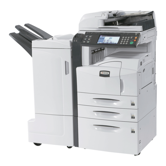
- Page 18 2GN/2GP/2GR-3 1-1-2 Parts names (1) Machine 16 17 Figure 1-1-1 Original cover (Option) 13. Toner container 25. Paper width guides Original size indicator plates 14. Toner container stopper 26. Multi purpose tray Clip holder 15. Waste toner box 27. Memory card cover holder Reception indicator 16.
- Page 19 2GN/2GP/2GR-2 (2) Operation panel Figure 1-1-2 System menu key/indicator 13. Memory indicator Status/Job cancel key/indicator 14. Error indicator Program key/indicator 15. Help key/indicator Application key/indicator 16. Logout key/indicator Counter key/indicator 17. Power key Copy key/indicator 18. Main power indicator Send key/indicator 19.
- Page 20 2GN/2GP/2GR 1-1-3 Machine cross section Light path Paper path Figure 1-1-3 Machine cross section Paper feed section Main charging section Optical section Developing section Transfer and separation section Cleaning and charge erasing section Fuser section Eject and switchback section Duplex section 1-1-6...
-
Page 21: Installation Environment
2GN/2GP/2GR-6 1-2 Installation 1-2-1 Installation environment ° ° Temperature: 10 to 32.5 C/50 to 90.5 Humidity: 15 to 80%RH Power supply: 120 V AC, 11.5 A 220 to 240 V AC, 6.3 A ± ± Power source frequency: 50 Hz 0.3%/60 Hz 0.3% Installation location... -
Page 22: Unpacking And Installation
2GN/2GP/2GR-1 1-2-2 Unpacking and installation (1) Installation procedure Start Connect the power cord. Unpack. Install the fixing brackets. Remove the tapes, spacers and pad. Install the optional paper feeder. Install the stylus pen and penholder. Carry out initial developer setting Release the lever holding mirror 1 and 2 frames. - Page 23 2GN/2GP/2GR-2 Moving the machine When moving the machine, pull out the four handles on the right and left sides and hold them. Handle Handle Handle Handle Figure 1-2-2 1-2-3...
- Page 24 2GN/2GP/2GR-7 Unpacking. Figure 1-2-3 Unpacking Machine 13. Hinge joints Outer case 14. Bar code labels Inner frame 15. Power cord Skid 16. Fixing brackets Bottom front left pad 17. Plastic bag Bottom front right pad 18. Operation guide Bottom rear left pad 19.
- Page 25 2GN/2GP/2GR-1 Remove the tapes, spacers and pad. 1. Remove two tapes. Spacers 2. Pull the lever and operation section is low- ered. 3. Remove two spacers. Remove waste textile on the operation panel, if any. 4. Remove the pad. Tape Tape Figure 1-2-4 Install the optional paper feeder.
- Page 26 2GN/2GP/2GR-1 Release of cassette lift plate. 1. Pull cassette 1 and 2 out. Lift plate stopper Remove the lift plate stopper from each cas- sette and attach it to the storage location. When moving the machine, attach the lift plate in original position. Figure 1-2-6 Load paper.
- Page 27 2GN/2GP/2GR 4. Align the paper flush against the left side of the cassette. Figure 1-2-9 Install the toner container. 1. Open the front cover. Toner container 2. Tap the top of the toner container five to six times. Figure 1-2-10 3.
- Page 28 2GN/2GP/2GR 4. Gently push the toner container into the Toner container machine along the rails. Push the container all the way into the machine until it locks in place. Figure 1-2-12 Install the waste toner box. 1. Install the waste toner box in the machine. 2.
- Page 29 2GN/2GP/2GR-1 Install the fixing brackets. 1. Remove two screws from the rear cover. Grooves 2. Hook the catch of fixing brackets onto the groove of round frame, and secure them using two screws removed before step. Fixing brackets Figure 1-2-14 Install the stylus pen and penholder.
- Page 30 2GN/2GP/2GR-1 Output an own-status report (maintenance item U000). 1. Enter 000 using the numeric keys and press the start key. 2. Select MAINTENANCE and press the start key to output a list of the current settings of the maintenance items. 3.
- Page 31 2GN/2GP/2GR-6 1-2-3 Installing the key counter (option) Installing the key counter requires the following component: Key counter (P/N 3025418011) Key counter set (P/N 302A369708) Supplied parts of key counter set: Key counter socket assembly (P/N 3029236241) Key counter cover (P/N 3066060011) Key counter mount (P/N 3066060041) Key counter retainer (P/N 302GR03020) Key counter cover retainer (P/N 302GR03010)
- Page 32 2GN/2GP/2GR-6 7. Pass the connector of the machine through Key counter Aperture the aperture in the key counter cover cover retainer retainer. 8. Insert the hook of the key counter cover M4 x 20 screw retainer in the slit of the upper right cover. (7BB100420H) 9.
- Page 33 2GN/2GP/2GR-8 1-2-4 Installing the expanded memory (option) Procedure 1. Press the power key on the operation panel to off. Make sure that the power indicator and the memory indicator are off before turning off the main power switch. And then unplug the power cable from the wall outlet.
- Page 34 2GN/2GP/2GR-8 This page is intentionally left blank. 1-2-14...
-
Page 35: Maintenance Mode
2GN/2GP/2GR 1-3 Maintenance Mode 1-3-1 Maintenance mode The machine is equipped with a maintenance function which can be used to maintain and service the machine. (1) Executing a maintenance item Start Press the status key. Enter “10871087” using Maintenance mode is entered. the numeric keys. -
Page 36: Maintenance Modes Item List
2GN/2GP/2GR-5 (2) Maintenance modes item list Section Item Content of maintenance item Initial setting* General U000 Outputting an own-status report U001 Exiting the maintenance mode U002 Setting the factory default data U003 Setting the service telephone number *************** U004 Displaying the machine number U005 Copying without paper U019... - Page 37 2GN/2GP/2GR-7 Section Item Content of maintenance item Initial setting* High voltage U100 Setting the main high voltage U101 Setting the other high voltages Developing bias AC component frequency at image formation Developing shift bias potential at image formation Developing bias AC component duty at image formation Transfer control voltage Separation control voltage U102...
- Page 38 2GN/2GP/2GR-7 Section Item Content of maintenance item Initial setting* Operation U241 Checking the operation of the switches of the finisher panel and U243 Checking the operation of the DP motors support U244 Checking the DP switches equipment U245 Checking messages U246 Setting the finisher 3000-sheet document finisher...
- Page 39 2GN/2GP/2GR-7 Section Item Content of maintenance item Initial setting* Others U928 Checking machine life counts U933 Setting the fax backup kit U935 Relay board maintenance U942 Setting of deflection for feeding from DP U943 Adjusting the prevent appearance of back side image U984 Checking the developing unit number U985...
-
Page 40: Event Log
2GN/2GP/2GR-7 (3) Contents of the maintenance mode items Maintenance Description item No. Outputting an own-status report U000 Description Outputs lists of the current settings of the maintenance items, and paper jam and service call occurrences. Outputs the event log or service status page. Printing a report is disabled either when a job is remaining in the buffer or when [Pause All Print Jobs] is pressed to halt printing. - Page 41 2GN/2GP/2GR-6 Maintenance Description item No. U000 Detail of event log Items Description System version System date Paper Jam Log Count. Event Remembers 1 to 16 of The total page count at Log code (2 digit, hexa- occurrence. If the the time of the paper decimal, 5 categories) occurrence of the previ- jam.
- Page 42 2GN/2GP/2GR-7 Maintenance Description item No. U000 Items Description Paper Jam Log 82: Jam in stapler cont. 83: Exit sensor stay jam 84: Jam in eject section of right sub tray (3000-sheet document finisher) 85: Jam in eject section of left sub tray (3000-sheet document finisher) 86: Jam in eject section of internal tray 1 (3000-sheet document finisher) 87: Jam in eject section of internal tray 2 (3000-sheet document finisher) 88: Jam in eject section of main tray (3000-sheet document finisher)
- Page 43 2GN/2GP/2GR-7 Maintenance Description item No. U000 Items Description (e) Detail of paper exit location (Hexadecimal) Paper Jam Log cont. 01: Face down (FD) 02: Face up (FU)/ Document finisher face up (FU)/ 3000-sheet document finisher left sub tray (FU) 03: Document finisher face down (FD) 04: Reserved 05: Reserved 06: 3000-sheet document finisher right sub tray (FU)
- Page 44 2GN/2GP/2GR-7 Maintenance Description item No. U000 Items Description Unknown Toner Log Count. Item Remembers 1 to 5 of The total page count at Unkown toner log code occurrence of unknown the time of the [Toner (1 byte, 2 categories) toner detection. If the Empty] error with using occurrence of the previ- an unknown toner con-...
-
Page 45: Service Status Page
2GN/2GP/2GR-2 Maintenance Description item No. Service status page (1) U000 Service Status Page Firmware version 2GR_2000.001.001 2007.01.17 Controller Information Memory Status Option Slot1 524288KB Option Slot2 524288KB Total 1048576KB Time Auto Continue Mode Local Time Zone +01:00_Amsterdam Auto Continue Timer Data and Time 10/27/2005 09:06 Time Server... - Page 46 2GN/2GP/2GR-2 Maintenance Description item No. Service status page (2) U000 Service Status Page Firmware version 2GR_2000.001.001 2006.01.17 Engine Information Counter (31) Printed (10) Engine ROM Version 2GR_1000.003.001 Total Printed Pages (11) Front Panel ROM Version 2GR_A000.001.019 Copier (12) NVRAM Version _Bb04B29_Bb04B29 Printer (13)
- Page 47 2GN/2GP/2GR-2 Maintenance Description item No. U000 Detail of service status page Description Supplement (10) Engine ROM version (11) Operation panel ROM version (12) NV RAM version _ Bb 04B29 _ Bb 04B29 (a) (b) (d) (e) (a) Consistency of the present software version and the database _ (underscore): OK * (Asterisk): NG...
- Page 48 2GN/2GP/2GR-2 Maintenance Description item No. U000 Description Supplement (29) Identification name for the security kit (30) Security kit version (31) Printed page counts Total/Copy/Printer/Fax (32) Scanned page counts Total/Copy/Other (33) Counts by paper sizes (34) Fax kit information This item is printed only when the optional fax kit is installed.
- Page 49 2GN/2GP/2GR-1 Maintenance Description item No. Setting the service telephone number U003 Description Sets the telephone number to be displayed when a service call code is detected. Purpose To set the telephone number to call service when installing the machine. Method Press the start key.
- Page 50 2GN/2GP/2GR-2 Maintenance Description item No. Displaying the ROM version U019 Description Displays the part number of the ROM fitted to each PWB. Purpose To check the part number or to decide, if the newest version of ROM is installed. Method 1.
- Page 51 2GN/2GP/2GR-2 Maintenance Description item No. Initializing all data U020 Description Initializes all the backup RAM on the main PWB to return to the original settings. Refer to *1 of the maintenance mode item list about the item initialized. Also, initializes the settings with the system menu in order to restore default settings simultaneously. Reregister the fax settings since the settings are initialized when the optional fax kit is installed.
- Page 52 2GN/2GP/2GR-2 Maintenance Description item No. Initializing counters and mode settings U021 Description Initializes all settings, except those pertinent to the type of machine, namely each counter, service call history and mode setting. Also initializes backup RAM according to region specification selected in maintenance item U252 Setting the destination.
- Page 53 2GN/2GP/2GR-2 Maintenance Description item No. HDD formatting U024 Description Initializes the HDD. In addition, the following settings are also initialized by initializing the HDD. System menu (user login administration, job accounting, address book, one-touch keys and document box etc.), shortcuts and panel programs Purpose To initialize the HDD when replacing the HDD after shipping.
- Page 54 2GN/2GP/2GR-1 Maintenance Description item No. Checking clutch operation U032 Description Turns each clutch on. Purpose To check the operation of each clutch. Method 1. Press the start key. 2. Select the clutch to be operated. 3. Press the start key. The clutch turns on for 1 s. Display Clutches Upper paper feed clutch (PFCL-U)
- Page 55 2GN/2GP/2GR-6 Maintenance Description item No. Adjusting the print start timing U034 Description Adjusts the leading edge registration or center line. Purpose Make the adjustment if there is a regular error between the leading edges of the copy image and original. Make the adjustment if there is a regular error between the center lines of the copy image and original.
- Page 56 2GN/2GP/2GR-5 Maintenance Description item No. Adjustment: center line adjustment U034 1. Select the item to be adjusted. Display Description Setting Initial Change in range setting value per step LEFT Adjustment of reference value 0 to 1000 0.042 mm MP TRAY Paper feed from MP tray* -500 to 500 0.042 mm...
- Page 57 2GN/2GP/2GR-5 Maintenance Description item No. Adjusting the deflection in the paper U051 Description Adjusts the deflection in the paper. Purpose Make the adjustment if the leading edge of the copy image is missing or varies randomly, or if the copy paper is Z-folded.
- Page 58 2GN/2GP/2GR-6 Maintenance Description item No. Setting the adjustment of the motor speed U053 Description Performs fine adjustment of the speeds of the motors. Purpose To adjust the speed of the respective motors when the magnification is not correct. Method 1. Press the start key. 2.
- Page 59 2GN/2GP/2GR-6 Maintenance Description item No. Turning the exposure lamp on U061 Description Turns the exposure lamp on. Purpose To check the exposure lamp. Method 1. Press the start key. 2. Select the item. Display Description Exposure lamp CIS (optional DP exposure lamp) 3.
- Page 60 2GN/2GP/2GR-1 Maintenance Description item No. Adjusting the scanner magnification U065 Description Adjusts the magnification of the original scanning. Purpose Make the adjustment if the magnification in the main scanning direction is incorrect. Make the adjustment if the magnification in the auxiliary scanning direction is incorrect. Caution Adjust the magnification of the scanner in the following order.
- Page 61 2GN/2GP/2GR-1 Maintenance Description item No. Adjusting the scanner leading edge registration U066 Description Adjusts the scanner leading edge registration of the original scanning. Purpose Make the adjustment if there is a regular error between the leading edges of the copy image and original. Adjustment 1.
- Page 62 2GN/2GP/2GR-1 Maintenance Description item No. Adjusting the scanner center line U067 Description Adjusts the scanner center line of the original scanning. Purpose Make the adjustment if there is a regular error between the center lines of the copy image and original. Adjustment 1.
- Page 63 2GN/2GP/2GR-1 Maintenance Description item No. Adjusting the scanning position for originals from the DP U068 Description Adjusts the position for scanning originals from the DP. Performs the test copy at the four scanning positions after adjusting. Purpose Used when the image fogging occurs because the scanning position is not proper when the DP is used. Run U071 to adjust the timing of DP leading edge when the scanning position is changed.
- Page 64 2GN/2GP/2GR-1 Maintenance Description item No. Adjustment: main scanning direction of CIS U070 1. Press the system menu key. 2. Place an original on the DP and press the start key to make a test copy. 3. Press the system menu key. 4.
- Page 65 2GN/2GP/2GR-1 Maintenance Description item No. Adjusting the DP scanning timing U071 Description Adjusts the DP original scanning timing. Purpose Make the adjustment if there is a regular error between the leading or trailing edges of the original and the copy image when the optional DP is used. Method 1.
- Page 66 2GN/2GP/2GR-2 Maintenance Description item No. Adjustment: trailing edge registration U071 1. Press the system menu key. 2. Place an original on the DP and press the start key to make a test copy. 3. Press the system menu key. 4. Change the setting value using the +/- or numeric keys. For copy example 1, increase the value.
- Page 67 2GN/2GP/2GR-1 Maintenance Description item No. Adjusting the DP center line U072 Description Adjusts the scanning start position for the DP original. Purpose Make the adjustment if there is a regular error between the centers of the original and the copy image when the optional DP is used.
- Page 68 2GN/2GP/2GR-1 Maintenance Description item No. Checking scanner operation U073 Description Simulates the scanner operation under arbitrary conditions. Purpose To check scanner operation. Start 1. Press the start key. 2. Select the item to be operated. Display Description SCANNER MOTOR Scanner operation HOME POSITION Home position operation DP READING...
- Page 69 2GN/2GP/2GR-6 Maintenance Description item No. Adjusting the DP input light luminosity U074 Description Adjusts the luminosity of the exposure lamp for scanning originals from the DP. Purpose Used if the exposure amount differs significantly between when scanning an original on the contact glass and when scanning an original from the DP.
- Page 70 2GN/2GP/2GR-6 Maintenance Description item No. Adjusting the correct exposure U081 Description Adjusts the correct exposure in text and photo mode, text mode or photo mode. Purpose To be executed as required. Setting 1. Press the start key. 2. Select the item to be set. Display Description Setting...
- Page 71 2GN/2GP/2GR-1 Maintenance Description item No. Outputting a MIP-PG pattern U089 Description Selects and outputs the MIP-PG pattern created in the machine. Purpose To check copier status other than scanner when adjusting image printing, using MIP-PG pattern output (with- out scanning). Method 1.
- Page 72 2GN/2GP/2GR-1 Maintenance Description item No. Setting the exposure density gradient U093 Description Changes the exposure density gradient in the manual density mode, depending on respective image quality modes. Purpose To set how the image density is altered by a change of one step in the manual density adjustment for respec- tive image quality modes.
- Page 73 2GN/2GP/2GR-6 Maintenance Description item No. Setting: Density in photo mode U093 1. Select the item to be set. 2. Adjust the setting using the +/- or numeric keys. Display Description Setting Initial range setting PHOTO DARKER Change in density when manual density is set dark 0 to 3 PHOTO LIGTER Change in density when manual density is set light 0 to 3 Increasing the setting makes the change in density larger, and decreasing it makes the change smaller.
- Page 74 2GN/2GP/2GR-1 Maintenance Description item No. Adjusting original size detection U099 Description Checks the operation of the original size detection sensor and sets the sensing threshold value. Purpose To adjust the sensitiveness of the sensor and size judgement time if the original size detection sensor mal- functions frequently due to incident light or the like.
- Page 75 2GN/2GP/2GR-3 Maintenance Description item No. Setting the main high voltage U100 Description Performs main charging. Purpose To check main charging. Method 1. Press the start key. 2. Select the item to be operated. 3. Press the start key. The selected operation starts. Display Description MC ON...
- Page 76 2GN/2GP/2GR-1 Maintenance Description item No. Setting the cleaning interval for the main charger U102 Description Changes the intervals at which the main charger is cleaned. Purpose To change the setting when the background is visible. Setting 1. Press the start key. 2.
- Page 77 2GN/2GP/2GR-1 Maintenance Description item No. Setting separation charger mode U114 Description Sets the separation charger mode. Purpose To change the setting if the fuser offset or carrier leaking occurs. Method 1. Press the start key. 2. Change the setting using the +/- or numeric keys. Display Description Setting range...
- Page 78 2GN/2GP/2GR-1 Maintenance Description item No. Initial setting for the developing unit U130 Description Replenishes toner to the developing unit to a certain level from the toner container that has been installed. Purpose To operate when installing the machine or replacing the developing unit. Method 1.
- Page 79 2GN/2GP/2GR-1 Maintenance Description item No. Checking/clearing the developing drive time U157 Description Displays the developing drive time for checking, or clearing a figure, which is used as a reference when cor- recting the toner control. Purpose To check the developing drive time after replacing the developing unit. Method Press the start key.
- Page 80 2GN/2GP/2GR-1 Maintenance Description item No. Resetting the fuser problem data U163 Description Resets the detection of a service call code indicating a problem in the fuser section. Purpose To prevent accidents due to an abnormally high fuser temperature. Method 1. Press the start key. 2.
- Page 81 2GN/2GP/2GR-1 Maintenance Description item No. Checking the fuser temperature U199 Description Displays the fuser temperature, the ambient temperature and the absolute humidity. Purpose To check the fuser temperature, the ambient temperature and the absolute humidity. Method ° Press the start key. The fuser temperature and ambient temperature are displayed in centigrade ( C) and the absolute humidity is displayed in percentage (%).
- Page 82 2GN/2GP/2GR-7 Maintenance Description item No. Checking DP operation U203 Description Simulates the original conveying operation separately in the optional DP. Purpose To check the DP operation. Method 1. Press the start key. 2. Place an original in the DP if running this simulation with paper. 3.
- Page 83 2GN/2GP/2GR-7 Maintenance Description item No. Checking the operation panel keys U207 Description Checks operation of the operation panel keys. Purpose To check operation of all the keys and LEDs on the operation panel. Method 1. Press the start key. The screen for executing is displayed. 2.
- Page 84 2GN/2GP/2GR-7 Maintenance Description item No. Operation panel lock U223 Description Sets the operation panel lock function to ON or OFF. Purpose To restrict operation in the system menu on the operation panel. Setting 1. Press the start key. 2. Select the item. Display Description Unlock...
- Page 85 2GN/2GP/2GR-6 Maintenance Description item No. Setting the limit for the ejection section of the built-in finisher U236 Description If the machine is equipped with an optional built-in finisher, this mode sets whether A5R/B5R/statement size paper is output to the machine eject tray or not. Purpose If the machine is equipped with an optional built-in finisher and if paper jams occur due to curling of paper in the built-in ejection section when two-sided copying onto A5R/B5R/statement size paper is performed, this...
- Page 86 2GN/2GP/2GR-2 Maintenance Description item No. Checking the operation of the finisher U240 Description Turns each motor and solenoid of the 3000-sheet document finisher ON. Purpose To check the operation of each motor and solenoid of the 3000-sheet document finisher. Method 1.
- Page 87 2GN/2GP/2GR-2 Maintenance Description item No. Method: Checking the solenoid of the 3000-sheet document finisher U240 1. Select the item to be operated. The solenoid turns on for 1 s. Display Solenoid FEED IN SOL Paper entry solenoid (PESOL) REAR DOWN SOL 1 Trailing edge holder solenoid 1 (TEHSOL1) REAR DOWN SOL 2 Trailing edge holder solenoid 2 (TEHSOL2)
- Page 88 2GN/2GP/2GR-2 Maintenance Description item No. Checking the operation of the switches of the finisher U241 Description Displays the status of each switch of the 3000-sheet document finisher. Purpose To check the operation of each switch of the 3000-sheet document finisher. Method 1.
- Page 89 2GN/2GP/2GR-2 Maintenance Description item No. Method: Checking the switch of the mailbox U241 1. Turn the respective switches on and off manually to check the status. When a switch is detected to be in the ON position, the display for that switch will be highlighted. Display Switches FEED IN SW...
- Page 90 2GN/2GP/2GR-1 Maintenance Description item No. Checking the DP switches U244 Description Displays the status of the respective switches in the optional DP. Purpose To check if respective switches in the optional DP operate correctly. Method 1. Press the start key. 2.
- Page 91 2GN/2GP/2GR-1 Maintenance Description item No. Setting the finisher U246 Description Provides various settings for the optional finisher, if furnished. Purpose Adjustment of registration stop timing in punch mode Adjust if skewed paper conveying occurs or if the copy paper is Z-folded in punch mode. Adjustment of paper stop timing in the punch mode To adjust this item when the position of a punch hole is different from the specified one.
- Page 92 2GN/2GP/2GR-1 Maintenance Description item No. Setting: adjustment of the paper stop timing U246 1. Select PUNCH POS ADJ. 2. Change the setting using the +/- or numeric keys. Setting Initial Change in Description range setting value per step Adjustment of the paper stop timing -10 to 10 0.49 mm If the distance of the position of a punch hole is smaller than the specified value A, increase the preset...
- Page 93 2GN/2GP/2GR-1 Maintenance Description item No. Setting: adjustment of slanted stapling home position U246 1. Select T-STAPLE HP ADJ. 2. Change the setting using the +/- or numeric keys. Setting Initial Change in Description range setting value per step ° Adjustment of slanted stapling home position -10 to 10 0.99 To increase the angle for slanted stapling (sample 1), decrease the preset value.
- Page 94 2GN/2GP/2GR-2 Maintenance Description item No. Setting: adjustment of booklet stapling position U246 Make sure that the center folding position is correct after adjustment. If the position is not correct, execute the adjustment of center folding position. 1. Select the [STAPLE POS ADJ 1], [STAPLE POS ADJ 2] or [STAPLE POS ADJ 3]. 2.
- Page 95 2GN/2GP/2GR-1 Maintenance Description item No. Setting the side registration cursor stop position U246 1. Select the desired cursor position. 2. Change the setting using the +/- or numeric keys. Display Description Setting Initial range setting FRONT Front side registration cursor stop position -4 to +4 REAR Rear side registration cursor stop position...
- Page 96 2GN/2GP/2GR-1 Maintenance Description item No. Setting the maintenance cycle U250 Description Displays and changes the maintenance cycle. Purpose To check and change the maintenance cycle. Method Press the start key. The currently set maintenance cycle is displayed. Setting 1. Change the setting using the +/- or numeric keys. Description Setting range Initial setting...
- Page 97 2GN/2GP/2GR-6 Maintenance Description item No. Setting the destination U252 Description Switches the operations and screens of the machine according to the destination. Purpose To be executed after initializing the backup RAM by running maintenance item U020, in order to return the set- ting to the value before replacement or initialization.
- Page 98 2GN/2GP/2GR-1 Maintenance Description item No. Selecting the timing for copy counting U260 Description Changes the copy count timing for the total counter and other counters. Purpose To be set according to user (copy service provider) request. If a paper jam occurs frequently in the optional document finisher when the number of copies is counted at the time of paper ejection, copies are provided without copy counts.
- Page 99 2GN/2GP/2GR-2 Maintenance Description item No. Setting the black line cleaning indication U326 Description Sets whether to display the cleaning guidance when detecting the black line. Purpose Displays the cleaning guidance in order to make the call for service with the black line decrease by the rubbish on the platen when scanning from the DP.
- Page 100 2GN/2GP/2GR-1 Maintenance Description item No. Setting the size conversion factor U332 Description Sets the coefficient of nonstandard sizes in relation to the A4/Letter size. The coefficient set here is used to convert the black ratio in relation to the A4/Letter size and to display the result in user simulation. Purpose To set the coefficient for converting the black ratio for nonstandard sizes in relation to the A4/Letter size.
- Page 101 2GN/2GP/2GR-2 Maintenance Description item No. Setting the ejection restriction U342 Description Sets or cancels the restriction on the number of sheets to be ejected continuously when the internal eject tray is selected as the eject location. Purpose According to user request, sets or cancels restriction on the number of sheets. Setting 1.
- Page 102 2GN/2GP/2GR-6 Maintenance Description item No. Adjusting margins of image printing U402 Description Adjusts margins for image printing. Purpose Make the adjustment if margins are incorrect. Adjustment 1. Press the start key. 2. Select the item to be adjusted. Setting Initial Change in Display Description...
- Page 103 2GN/2GP/2GR-6 Maintenance Description item No. Adjusting margins for scanning an original on the platen U403 Description Adjusts margins for scanning the original on the contact glass. Purpose Make the adjustment if margins are incorrect. Adjustment 1. Press the start key. 2.
- Page 104 2GN/2GP/2GR-6 Maintenance Description item No. Adjusting margins for scanning an original from the DP U404 Description Adjusts margins for scanning the original from the DP. Purpose Make the adjustment if margins are incorrect when the optional DP is used. Caution Before making this adjustment, ensure that the following adjustments have been made in maintenance mode.
- Page 105 2GN/2GP/2GR-5 Maintenance Description item No. Adjusting the leading edge registration for memory image printing U407 Description Adjusts the leading edge registration during memory copying. Purpose Make the following adjustment if there is a regular error between the leading edge of the copy image on the front face and that on the reverse face during duplex switchback copying.
- Page 106 2GN/2GP/2GR-2 Maintenance Description item No. Adjusting the scanner automatically U411 Description Uses a specified original and automatically adjusts the following items in the scanner and the DP scanning sections. Purpose To perform automatic adjustment of various items in the scanner and the DP scanning sections. To adjust scanner automatically when initializing the machine using the maintenance item U020 or U022.
- Page 107 2GN/2GP/2GR-5 Maintenance Description item No. Method: DP(FACE UP) U411 1. Select [DP(FACE UP)]. 2. Set a specified original (P/N: 2AC68241) in the DP. Cut the trailing edge of the original. 128 1 mm 60 1 mm Cut with the edge of black belt. Figure 1-3-28 3.
- Page 108 2GN/2GP/2GR-5 Maintenance Description item No. U411 5. Select the item (place all oroginals face down). Display Description Original to be used for adjustment (P/N) Automatic adjustment of second page using the DP 2AC68241/303JX57010/ for: original size magnification/leading edge timing/ 303JX57020 center line, input gamma, chromatic aberration filter, MTF filter and matrix.
- Page 109 2GN/2GP/2GR-2 Maintenance Description item No. Error Codes U411 Codes Description ERROR 01 Black band detection error (scanner leading edge registration) ERROR 02 Black band detection error (scanner center line) ERROR 03 Black band detection error (scanner main scanning direction magnification) ERROR 04 Black band is not detected (scanner leading edge registration) ERROR 05...
- Page 110 2GN/2GP/2GR-7 Maintenance Description item No. Setting the target U425 Description Enters the lab values that is indicated on the back of the chart (P/N: 302FZ56990) used for adjustment. Purpose Performs data input in order to correct for differences in originals during automatic adjustment. Method 1.
- Page 111 2GN/2GP/2GR-7 Maintenance Description item No. U425 Left edge 30 mm 148.5 mm 267 mm Leading edge Black belt (b) 50 mm Black belt (a) 105 mm [MAIN ADJ] = ((A + C) / 2 + B) / 2 [SUB ADJ] = ((D + F) / 2 + E) / 2 190 mm Original for adjustment...
- Page 112 2GN/2GP/2GR-1 Maintenance Description item No. Checking/clearing copy counts by paper feed locations U901 Description Displays or clears copy counts by paper feed locations. Purpose To check the time to replace consumable parts. Also to clear the counts after replacing the consumable parts. Method Press the start key.
- Page 113 2GN/2GP/2GR-1 Maintenance Description item No. Checking/clearing the paper jam counts U903 Description Displays or clears the jam counts by jam locations. Purpose To check the paper jam status. Also to clear the jam counts after replacing consumable parts. Method 1. Press the start key. 2.
- Page 114 2GN/2GP/2GR-1 Maintenance Description item No. Checking/clearing counts by optional devices U905 Description Displays or clears the counts of optional DP or finisher. Purpose To check the use of optional DP and finisher. Also to clear the counts after replacing consumable parts. Method 1.
- Page 115 2GN/2GP/2GR-7 Maintenance Description item No. Clearing the black ratio data U910 Description Clears the accumulated black ratio data for A4 sheet. Purpose To clear data as required at times such as during maintenance service. Method 1. Press the start key. 2.
- Page 116 2GN/2GP/2GR-7 Maintenance Description item No. Setting backup data reading/writing U917 Description Retrieves the backup data to a USB memory from the machine; or writes the data from the USB memory to the machine. Purpose To store and write data when replacing the HDD. Supplement This maintenance item is supported with the firmware version later than below.
- Page 117 2GN/2GP/2GR-7 Maintenance Description item No. Error Codes U917 Codes Description Codes Description 321d0001 Parameter error 321d1012 File retrieving error 321d0002 Unsupported configuration name 321d1013 One-touch file open error 321d0003 Process generation error 321d1014 User managements file open error 321d0004 PIPE generation error 321d1015 Log file copy error to the USB memory 321d0005...
- Page 118 2GN/2GP/2GR-7 Maintenance Description item No. Checking the copy counts U920 Description Checks the copy counts. Purpose To check the copy counts. Method Press the start key. The current counts of copy counter, printer counter and fax counter are displayed. Completion Press the stop key.
- Page 119 2GN/2GP/2GR-7 Maintenance Description item No. Setting the fax backup kit U933 Description Initializes optional fax backup kit (CF) and restore the backup data. Purpose To initialize the CF when call for service (C0700) occurs. Also, to restore data when the hard disk has been damaged.
- Page 120 2GN/2GP/2GR-7 Maintenance Description item No. Relay board maintenance U935 Description Sets the machine status temporarily when call for service (C0060) occurs. However, after the setting, call for service (C0060) occurs again when progress of period. Setting 1. Press the start key. 2.
- Page 121 2GN/2GP/2GR-7 Maintenance Description item No. Adjusting the prevent appearance of back side image U943 Description Adjust the gamma background for CIS. Purpose The back side image are adjusted when scanning the back side through the DP and then the image are inter- pose itself between CIS chips.
- Page 122 2GN/2GP/2GR-7 Maintenance Description item No. HDD scandisk U989 Description Restores data in the hard disk by scanning the disk. Purpose If power is turned off while accessing to the hard disk is performed, the control information in the hard disk drive may be damaged.
- Page 123 2GN/2GP/2GR-7 Maintenance Description item No. Outputting a VTC-PG pattern U993 Description Selects and outputs a VTC-PG pattern created in the machine. Purpose When performing respective image printing adjustments, used to check the machine status apart from that of the scanner with a non-scanned output VTC-PG pattern. Method 1.
- Page 124 2GN/2GP/2GR-7 1-3-2 User management In addition to a maintenance function for service, the machine is equipped with a management function which can be oper- ated by users. In this user management mode, settings such as default settings can be changed. (1) Using the user management mode Start Press the system menu key.
- Page 125 2GN/2GP/2GR-7 (2) Common settings Setting range 120 V specifications X: 2 to 17" (in 0.01" increments), Switching the language for display Y: 2 to 11.69" (in 0.01" increments) Select the language displayed on the touch panel. 220-240 V specifications 1. Press [Change] of Language. X: 50 to 432 mm (in 1 mm increments), 2.
- Page 126 2GN/2GP/2GR-7 3. Press [OK]. 4. Select the weight and press [OK]. 4. Press [Change] of Media Type to select type of Light/Normal 1/Normal 2/Normal 3/Heavy 1/ paper and press [OK]. Heavy 2/Heavy 3/Extra Heavy Type of paper: Plain, Rough, Vellum, Recycled, 5.
- Page 127 2GN/2GP/2GR-7 Special paper action Function defaults To print on Prepunched, Preprint, and Letterhead, punch- Set the defaults for available settings such as copying holes might fail to be aligned or print direction might be and sending. Setting the frequently-used values as upside down depending on how to set the originals and defaults makes subsequent jobs easier.
- Page 128 2GN/2GP/2GR-7 Density Setting range Set the default density. 120 V specifications: -0.75 to 0.75" 1. Press [Next] of Function Defaults and then (in 0.01" increments) [Change] of Density. 220-240 V specifications: -18 mm to 18 mm 2. Press [Manual (Normal 0)] or [Auto]. (in 1 mm increments) 3.
- Page 129 2GN/2GP/2GR-7 EcoPrint (3) Copy settings Select the EcoPrint default. 1. Press [Next] of Function Defaults, cursor down key Border erase to back page and then [Change] of EcoPrint. Select the border erase method for back of page. 2. Press [Off] or [On]. 1.
- Page 130 2GN/2GP/2GR-7 (4) Sending settings (5) Document box/Removable memory settings Quick setup registration Job box Select the sending functions to be registered for Quick Setup. Quick copy/Proof and hold print box Six keys of the Quick Setup screen are allocated to typi- To preserve the free space on the hard disk, the maxi- cal functions but can be changed as necessary.
- Page 131 2GN/2GP/2GR-7 Maximum number of repeat copy jobs (6) Printer settings Change the maximum number of Repeat Copy jobs to retain in the document box. Emulation 1. Press [Next] of Job Box. 2. Press [Change] of Repeat Copy Job Retention. Selection of emulation 3.
- Page 132 2GN/2GP/2GR-7 Resolution Form feed timeout Select default resolution. Receiving print data from the computer, the machine may 1. Press [Change] of Resolution. sometimes have to wait if there is no information identify- 2. Select default resolution. ing the last page has no data any more to be printed. 300 dpi/600 dpi/Fast1200 When the preset timeout passes, the machine automati- 3.
- Page 133 2GN/2GP/2GR-7 (7) Network setup (8) Printing reports/Sending notice TCP/IP setup by entering IP addresses Printing reports Set up TCP/IP to connect to the Windows network. Set Print reports to check the machine settings and status. the IP addresses, subnet masks, and gateway Default settings for printing the result reports can also be addresses.
- Page 134 2GN/2GP/2GR-7 (9) Adjustment/Maintenance Silent mode Make the machine run more quietly. Select the mode when the running noise is annoying. Copy density adjustment 1. Press [Change] of Silent Mode. Adjust copy density. 2. Press [Off] or [On]. 1. Press [Next] of Copy Density Adjustment. 3.
- Page 135 2GN/2GP/2GR-7 (10) Date/Timer Auto error clear If an error occurs during printing, the print job stops to wait for the next step to be taken by the user. In the auto Date/Time error clear mode, automatically clear the error after a set Set the date and time for the location where you use the amount of time elapses.
- Page 136 2GN/2GP/2GR-7 (11) Editing Destination (Address Book/Adding 8. Press [Add]. One-Touch Keys) 9. Select a destination (individual) to add to the group. 10. Press [OK]. Save frequently used destinations to Address Book or 11. Check if the selected destination was added to the One-touch Keys and the saved destinations can be group and press [Register].
- Page 137 2GN/2GP/2GR-7 (12) Restarting the system/Connecting the PC (13) User login administration User login administration specifies how the user access Restarting the system is administered on this machine. Restart the CPU without turning the main power switch off. Enabling/Disabling User Login Administration It works to deal with the machine's unstable operation.
- Page 138 2GN/2GP/2GR-7 (14) Job accounting 4. Select [Off], [Counter Limit], or [Reject Usage]. When selecting [Counter Limit], enter the number of Job accounting Manages the copy/print count incurred by pages using the [+]/[-] or numeric keys. individual accounts by assigning an ID to each account. Setting range: 1 to 999999 5.
- Page 139 2GN/2GP/2GR-7 Counting by paper size Count the number of pages by paper size (e.g. Letter). 1. When user login administration is invalid, the user authentication screen is displayed. Enter a login user name and password, and press [Login]. 2. Press [Next] of Job Accounting Setting, [Next] of Default Setting, [Change] of Count by Paper Size, [Change] of Paper Size 1 to 5 and then [On].
- Page 140 2GN/2GP/2GR This page is intentionally left blank. 1-3-106...
- Page 141 2GN/2GP/2GR-6 1-4 Troubleshooting 1-4-1 Paper misfeed detection (1) Paper misfeed indication When a paper misfeed occurs, the machine immediately stops copying and displays the jam location on the operation panel. Paper misfeed counts sorted by the detection condition can be checked in maintenance item U903. To remove paper jammed in the machine, open the front cover, left cover or pull the cassette out.
- Page 142 2GN/2GP/2GR-1 (2) Paper misfeed detection conditions OFSW ORSW Document processor DPTSW2 DPTSW1 Built-in finisher PCSW FSSW DUPPCSW DUPFCL MPFCL MPPFCL FCL1 FSW1 MPFSW PFCL-U FCL2 FSW2 PFCL-L FCL3 FSW3 PFPFCL1 PPSENS1 PFPFCL1 PPSENS2 PPSENS3 PFPFCL2 PFFCL PFFSW PFPFCL2 Paper feeder 3000-sheet paper feeder Figure 1-4-2 1-4-2...
- Page 143 2GN/2GP/2GR Section Description Conditions Specified time System Cover is open during copying. Cover open Secondary paper feed does not start within specified time 30 s Secondary paper feed of arrival of paper at the registration section. does not start A communication sequence error occurs between the 3000-sheet paper machine and the 3000-sheet paper feeder.
- Page 144 2GN/2GP/2GR Section Description Conditions Specified time Paper The registration switch (RSW) does not turn on within 1657 ms (30 ppm)/ feed Misfeed in vertical specified time of feed switch 1 (FSW1) turning on. 1283 ms (40/50 ppm) section paper conveying sec- Feed switch 1 (FSW1) does not turn on within specified 1910 ms (30 ppm)/ tion...
- Page 145 2GN/2GP/2GR-5 Section Description Conditions Specified time Paper The feed switch 1 (FSW1) does not turn off within speci- 1910 ms (30 ppm)/ feed Multiple sheets in verti- fied time of the feed switch 2 (FSW2) turning off. 1478 ms (40/50 ppm) section cal conveying section The feed switch 2 (FSW2) does not turn off within speci-...
- Page 146 2GN/2GP/2GR-2 Section Description Conditions Specified time Feedshift The feedshift switch (FSSW) does not turn on within 1545 ms (30 ppm)/ section Misfeed in feedshift specified time of the start of eject motor (EM) reverse 1196 ms (40/50 ppm) section rotation. During paper switchback operation, the feedshift switch 2989 ms (30 ppm)/ (FSSW) does not turn off within specified time of the its...
- Page 147 2GN/2GP/2GR-1 Section Description Conditions Specified time Optional The document processor top cover is opened during orig- Document processor inal feeding. top cover open The following switches turns on when starting the original paper feed. Original feed switch (OFSW) Original registration switch (ORSW) DP timing switch 1/2 (DPTSW1/2) Optional Paper ejection is not output from the machine to the doc-...
- Page 148 2GN/2GP/2GR Section Description Conditions Specified time Optional (3000-sheet document finisher) 1182 ms finisher Exit sensor stay jam Eject switch 1 (ESW1) is not turned off within specified time of its turning on. (Document finisher) 1680 ms In the straight mode, the exit sensor (EXS) is not turned off within specified time of its turning on.
- Page 149 2GN/2GP/2GR-2 Section Description Conditions Specified time Optional The centerfold paper entry sensor (CPES) does not turn 1770 ms (30 ppm)/ finisher Jam in centerfold unit off within specified time of centerfold paper detection sen- 1370 ms (40/50 ppm) (3000-sheet document sor (CPDS) turning on.
- Page 150 2GN/2GP/2GR Section Description Conditions Specified time Optional The reverse sensor (REVS) does not turn on within spec- 1071 ms finisher Reverse sensor jam ified time of paper entry sensor (PES) turning on. (document finisher The reverse sensor (REVS) is not turned on within speci- 435 ms only) fied time.
- Page 151 2GN/2GP/2GR (3) Paper misfeeds Problem Causes/check procedures Corrective measures A piece of paper torn from Check visually and remove it, if any. A paper jam in the copy paper is caught paper feed, convey- around feed switch 1/2/3, ing or eject section is registration switch, eject indicated as soon as switch or feedshift switch.
- Page 152 2GN/2GP/2GR-2 Problem Causes/check procedures Corrective measures Optional paper feeder A paper jam in the Paper is extremely curled. Replace the paper. paper feed section is indicated during Check if the paper feed pul- Check visually and replace any deformed pulleys. copying (no paper ley, forwarding pulley and feed from optional...
- Page 153 2GN/2GP/2GR Problem Causes/check procedures Corrective measures Paper is extremely curled. Replace the paper. A paper jam in the Check if the MP paper feed Check visually and replace any deformed pulleys. paper feed section is pulley, MP forwarding pulley indicated during and MP separation pulley copying (no paper are deformed.
- Page 154 2GN/2GP/2GR-2 Problem Causes/check procedures Corrective measures Paper is extremely curled. Replace the paper. A paper jam in the Check if the paper side Check visually and replace. paper feed section is guides are deformed. indicated during copying (jam in 3000- Defective paper path sen- With 5 V DC present at CN6-6 on the paper feeder main PWB, sheet paper feeder...
- Page 155 2GN/2GP/2GR-6 Problem Causes/check procedures Corrective measures (13) Broken feed switch 1/2/3 or Check visually and replace switch. A paper jam in the MP feed switch actuator. paper feed section is Defective switch. Run maintenance item U031 and turn switch on and off manually. indicated during Replace the switch if indication of the corresponding switch on the copying (multiple...
- Page 156 2GN/2GP/2GR Problem Causes/check procedures Corrective measures (17) Broken eject switch or feed- Check visually and replace switch. A paper jam in the shift switch actuator. fuser section is indi- Defective switch. Run maintenance item U031 and turn switch on and off manually. cated during copying Replace the switch if indication of the corresponding switch on the (jam in fuser section).
- Page 157 2GN/2GP/2GR-5 Problem Causes/check procedures Corrective measures (21) Broken feedshift switch or Check visually and replace switch. A paper jam in the duplex paper conveying duplex section is indi- switch actuator. cated during copying Defective switch. Run maintenance item U031 and turn switch on and off manually. (jam in duplex paper Replace the switch if indication of the corresponding switch on the conveying section 1).
- Page 158 2GN/2GP/2GR-5 Problem Causes/check procedures Corrective measures (28) Defective switch. Run maintenance item U244 and turn switch on and off manually. An original jams in Replace the switch if indication of the corresponding switch on the optional DP is indi- touch panel is not displayed in reverse. cated during copying Original registration switch, DP timing switch 1 (a jam in the original...
- Page 159 2GN/2GP/2GR-5 Problem Causes/check procedures Corrective measures (32) 3000-sheet document finisher/document finisher A paper jam in Defective staple home posi- Run maintenance item U241 and turn the staple home position optional document tion sensor. sensor on and off manually. Replace the sensor if indication of the finisher is indicated corresponding sensor on the touch panel is not displayed in during copying (fin-...
- Page 160 2GN/2GP/2GR-5 Problem Causes/check procedures Corrective measures (36) Defective internal tray Run maintenance item U241 and turn internal tray paper entry A paper jam in paper entry sensor 1. sensor 1 on and off manually. Replace the original switchback optional document switch if indication of the corresponding switch on the touch panel finisher is indicated is not displayed in reverse.
- Page 161 2GN/2GP/2GR-5 Problem Causes/check procedures Corrective measures (42) Defective reverse sensor. With 5 V DC present at CN14-5 on the finisher main PWB, check A paper jam in if CN14-7 on the finisher main PWB remains low or high when the optional document reverse sensor is turned on and off.
- Page 162 2GN/2GP/2GR-6 1-4-2 Self-diagnosis (1) Self-diagnostic function This unit is equipped with a self-diagnostic function. When a problem is detected, copying is disabled and the problem dis- played as a code consisting of C followed by a number, indicating the nature of the problem. A message is also displayed requesting the user to call for service.
- Page 163 2GN/2GP/2GR-6 Measures against the service codes detecting fuser problems If one of the following service codes is detected, take actions to clear the cause of the trouble and perform maintenance item U163 to reset the service code. Code Contents Code Contents C6000 Fuser heater break...
- Page 164 2GN/2GP/2GR-6 Remarks Code Contents Causes Check procedures/corrective measures C0610 DIMM problem Defective main Replace the main PWB and check for cor- The DIMM on the main PWB does not PWB. rect operation. operate correctly. Defective DIMM. Replace the DIMM and check for correct operation.
- Page 165 2GN/2GP/2GR-1 Remarks Code Contents Causes Check procedures/corrective measures C1010 Upper lift motor error Poor contact in the Check the connection of connector of upper When cassette 1 is inserted, upper lift connector termi- lift motor and the connector YC13 on the limit switch does not turn on within 12 s nals.
- Page 166 2GN/2GP/2GR Remarks Code Contents Causes Check procedures/corrective measures C1030 Paper feeder lift motor 1 error Poor contact in the Check the connection of connector on the (optional paper feeder) connector termi- engine PWB and the connector on the paper When optional cassette 3 is inserted, nals.
- Page 167 2GN/2GP/2GR Remarks Code Contents Causes Check procedures/corrective measures C1120 Paper feeder left lift position problem Poor contact in the Check the connection of connector on the (optional 3000-sheet paper feeder) connector termi- engine PWB and the connector on the paper Paper feeder switch 2 does not turn on nals.
- Page 168 2GN/2GP/2GR-1 Remarks Code Contents Causes Check procedures/corrective measures C2000 Drive motor problem Poor contact in the Check the connection of connector YC11 on Stable OFF is detected for 1 s continu- connector termi- the engine PWB and the connector on the ously after drive motor stability.
- Page 169 2GN/2GP/2GR Remarks Code Contents Causes Check procedures/corrective measures C2600 Paper feeder paper conveying motor Poor contact in the Check the connection of connector on the error (optional 3000-sheet paper connector termi- engine PWB and the connector on the paper feeder) nals.
- Page 170 2GN/2GP/2GR Remarks Code Contents Causes Check procedures/corrective measures C3210 CIS lamp problem Poor contact in the Check the connection of connector on the After the reading starting, when input connector termi- main PWB and the connector on the DP value at the time of CIS illumination does nals.
- Page 171 2GN/2GP/2GR-1 Remarks Code Contents Causes Check procedures/corrective measures C4010 Polygon motor steady-state problem Poor contact in the Check the connection of connector YC8 on Stable OFF is detected for 20 s continu- connector termi- the engine PWB and laser scanner unit, and ously after polygon motor stability.
- Page 172 2GN/2GP/2GR-3 Remarks Code Contents Causes Check procedures/corrective measures C6050 Abnormally low fuser unit thermistor Defective fuser Replace the fuser heater M or S. temperature heater M or S. Fuser unit thermistor 1 is detected 80°C/ Installation defec- Check the mounting state of the fuser unit 176°F less than 1 s continuously during tiveness on fuser thermistor 1.
- Page 173 2GN/2GP/2GR Remarks Code Contents Causes Check procedures/corrective measures C7810 Short-circuited external thermistor Poor contact in the Check the connection of connector YC14 on The thermistor input value is 0.5 V or connector termi- the engine PWB and the continuity across less.
- Page 174 2GN/2GP/2GR Remarks Code Contents Causes Check procedures/corrective measures C8050 Paper conveying belt motor 1 prob- Poor contact in the Check the connection of connector YC2 on lem (optional 3000-sheet document connector termi- the internal tray PWB and the connector on finisher) nals.
- Page 175 2GN/2GP/2GR-1 Remarks Code Contents Causes Check procedures/corrective measures C8140 Main tray problem (optional 3000- Poor contact in the Check the connection of connector YC6 on sheet document finisher) connector termi- the finisher main PWB and the connector on The main tray is not detected by the nals.
- Page 176 2GN/2GP/2GR-1 Remarks Code Contents Causes Check procedures/corrective measures C8170 Side registration motor 1 problem Poor contact in the Check the connection of connector YC2 on (optional 3000-sheet document fin- connector termi- the internal tray PWB and the connector on isher) nals.
- Page 177 2GN/2GP/2GR-1 Remarks Code Contents Causes Check procedures/corrective measures C8180 Side registration motor 2 problem Poor contact in the Check the connection of connector YC8 on (optional 3000-sheet document fin- connector termi- the internal tray PWB and the connector of isher) nals.
- Page 178 2GN/2GP/2GR Remarks Code Contents Causes Check procedures/corrective measures C8210 Stapler moving motor 1 error Poor contact in the Check the connection of connector YC9 on (optional 3000-sheet document fin- connector termi- the finisher main PWB and the connector of isher) nals.
- Page 179 2GN/2GP/2GR Remarks Code Contents Causes Check procedures/corrective measures C8300 Centerfold unit communication error Poor contact in the Check the connection of connector YC22 on (optional centerfold unit of 3000-sheet connector termi- the finisher main PWB and the continuity document finisher) nals.
- Page 180 2GN/2GP/2GR-2 Remarks Code Contents Causes Check procedures/corrective measures C8350 Centerfold side registration motor 2 Poor contact in the Check the connection of connector YC7 on problem (optional centerfold unit of connector termi- the centerfold main PWB and the connector 3000-sheet document finisher) nals.
- Page 181 2GN/2GP/2GR-2 Remarks Code Contents Causes Check procedures/corrective measures C8510 Mailbox drive motor problem Poor contact in the Check the connection of connector YC2 on (optional mailbox of 3000-sheet docu- connector termi- the mailbox main PWB and the connector of ment finisher) nals.
- Page 182 2GN/2GP/2GR Remarks Code Contents Causes Check procedures/corrective measures C9000 DP communication problem Poor contact in the Check the connection of connector YC7 on (optional DP) connector termi- the scanner PWB and the connector of the A communication error is detected. nals.
- Page 183 2GN/2GP/2GR-6 Remarks Code Contents Causes Check procedures/corrective measures F000 Operation panel PWB communication Defective main Replace the main PWB and check for cor- error PWB. rect operation. Defective opera- Replace the operation panel PWB and tion panel PWB. check for correct operation. F010 Main PWB checksum error Defective main...
- Page 184 2GN/2GP/2GR 1-4-3 Image formation problems (1)No image appears (2)No image appears (3)Image is too light. (4)Background is (5)A white line (entirely white). (entirely black). visible. appears longitudi- nally. See page 1-4-45. See page 1-4-45. See page 1-4-46. See page 1-4-46. See page 1-4-46.
- Page 185 2GN/2GP/2GR (1) No image appears (entirely white). Copy example Causes Check procedures/corrective measures No trans- The connector terminals Reinsert the connector. Also check for continuity within the fer charg- of the high voltage PWB connector cable. If none, remedy or replace the cable. ing.
- Page 186 2GN/2GP/2GR (3) Image is too light. Copy example Causes Check procedures/corrective measures Insufficient toner. If the display shows the message requesting toner replenish- ment, replace the container. Deteriorated toner. Perform the drum refresh operation. Defective The connector terminals Reinsert the connector. Also check for continuity within the transfer of the high voltage PWB connector cable.
- Page 187 2GN/2GP/2GR (6) A black line appears longitudinally. Copy example Causes Check procedures/corrective measures Dirty contact glass. Clean the contact glass. Dirty or flawed drum. Perform the drum refresh operation. If the drum is flawed, replace the drum unit (see page 1-5-25). Deformed or worn cleaning blade.
- Page 188 2GN/2GP/2GR (10) Image is blurred. Copy example Causes Check procedures/corrective measures Scanner moves erratically. Check if there is any foreign matter on the front and rear scanner rails. If any, remove it. Deformed press roller. Replace the press roller (see page 1-5-32). Paper conveying section drive prob- Check the gears and belts and, if necessary, grease them.
- Page 189 2GN/2GP/2GR (14) Offset occurs. Copy example Causes Check procedures/corrective measures Defective cleaning blade. Replace the drum unit (see page 1-5-25). Defective fuser unit. Check the heat roller and press roller. Wrong types of paper. Check if the paper meets specifications. Replace paper. (15) Image is partly missing.
- Page 190 2GN/2GP/2GR (18) Image center does not align with the original center. Copy example Causes Check procedures/corrective measures Misadjusted image center line. Run maintenance item U034 to readjust the center line of image printing (see page 1-3-22). Misadjusted scanner center line. Run maintenance item U067 to readjust the scanner leading edge registration (see page 1-3-28).
-
Page 191: Electric Problems
2GN/2GP/2GR-2 1-4-4 Electric problems Troubleshooting to each failure must be in the order of the numbered symptoms. Problem Causes Check procedures/corrective measures 1. The power cord is not Check the contact between the power plug and the outlet. The machine does plugged in properly. - Page 192 2GN/2GP/2GR Problem Causes Check procedures/corrective measures 1. Poor contact in the con- Reinsert the connector. Also check for continuity within the con- The exposure lamp nector terminals. nector cable. If none, remedy or replace the cable. does not turn on or 2.
- Page 193 2GN/2GP/2GR Problem Causes Check procedures/corrective measures (11) 1. Poor contact in the touch Reinsert the connector. Also check for continuity within the con- The touch panel keys panel connector termi- nector cable. If none, remedy or replace the cable. do not work. nals.
- Page 194 2GN/2GP/2GR Problem Causes Check procedures/corrective measures (15) 1. Poor contact in the con- Reinsert the connector. Also check for continuity within the con- The message nector terminals of front nector cable. If none, remedy or replace the cable. requesting cover to cover switch, left cover 1 be closed is dis- switch or left cover 2...
-
Page 195: Mechanical Problems
2GN/2GP/2GR 1-4-5 Mechanical problems Problem Causes/check procedures Corrective measures Check if the surfaces of the following rollers or Clean with isopropyl alcohol. No primary paper feed. pulleys are dirty with paper powder: upper/ lower forwarding pulleys, upper/lower paper feed pulleys, upper/lower separation pulleys, feed rollers, registration rollers, MP forward- ing pulley, MP paper feed pulley and MP sep- aration pulley. - Page 196 2GN/2GP/2GR Problem Causes/check procedures Corrective measures Paper is extremely curled. Replace the paper. Paper jams. Deformed guides along the paper conveying Check visually and replace any deformed path. guides. Check if the contact between the right and left Check visually and remedy if necessary. registration rollers is correct.
-
Page 197: Send Error Code
2GN/2GP/2GR-1 1-4-6 Send error code (1) Scan to SMB error codes Remarks Code Display Causes Check procedures/corrective measures 1102 Error: User/Password or Domain name is not entered. Enter the user name with the form of either Shared Name/Folder Name [Domain¥User], [Domain/User] or [Domain@User]. - Page 198 2GN/2GP/2GR-1 (2) Scan to FTP error codes Remarks Code Display Causes Check procedures/corrective measures 1101 Error: Host name Enter the disable host name/ Enter the correct host name or IP address. IP address. 1102 Error: User/Password Domain name is not entered. Enter the user name with the form of either [Domain¥User] or [Domain/User].
- Page 199 2GN/2GP/2GR-1 (3) Scan to E-mail error codes Remarks Code Display Causes Check procedures/corrective measures 1101 Error: Host name SMTP sever name is not set. Register [SMTP Server Name] in Error SMTP server name. [Advanced]-[SMTP] -[General] in COMMAND CENTER. 1102 Error: User/Password User ID for the authentication Enter the correct user ID/password for is not entered or entered...
- Page 200 2GN/2GP/2GR-1 (4) Network Twain error codes Remarks Code Display Causes Check procedures/corrective measures 2202 Error: Network transfer with Response is not returned Check the network connection (cable. net- timeout from the server above speci- work condition within LAN, etc.). fied time. 9181 Error: Page max count over The number of pages of a...
-
Page 201: Precautions For Assembly And Disassembly
2GN/2GP/2GR 1-5 Assembly and Disassembly 1-5-1 Precautions for assembly and disassembly (1) Precautions Before starting disassembly, press the power key on the operation panel to off. Make sure that the power indicator and the Memory indicator are off before turning off the main power switch. And then unplug the power cable from the wall outlet. Turning off the main power switch before pressing the power key to off may cause damage to the equipped hard disk. - Page 202 A black-colored band when seen through the left side window A shiny or gold-colored band when seen through the right side window The above will reveal that the toner container is a genuine Kyocera Mita branded toner container, otherwise, it is a coun- terfeit.
- Page 203 2GN/2GP/2GR 1-5-2 Paper feed section (1) Detaching and refitting the forwarding, paper feed and separation pulleys Follow the procedure below to replace the forwarding, paper feed and separation pulleys. Procedure Removing the primary paper feed units 1. Open the front cover and pull out the cas- settes 1 and 2.
- Page 204 2GN/2GP/2GR Removing the paper feed pulley Stop ring 7. Remove two stop rings from the primary paper feed unit. Stop ring 8. Pull the paper feed pulley shaft in the direc- tion of the arrow and remove the paper feed pulley.
- Page 205 2GN/2GP/2GR-1 (2) Detaching and refitting the MP separation, MP paper feed and MP forwarding pulleys Follow the procedure below to replace the MP separation, MP paper feed and MP forwarding pulleys. Procedure Removing the MP unit 1. Remove four screws and remove the right lower cover.
- Page 206 2GN/2GP/2GR-1 5. Raise the MP separation shaft as shown in the figure, remove the holder plate and the bushing, and then remove the MP separa- tion pulley. Holder plate Take care not to remove the spring pin of the gear at the rear of the MP separation pulley Bushing shaft.
- Page 207 2GN/2GP/2GR-1 9. Raise the MP paper feed pulley shaft as Stop ring shown in the figure, remove the stop ring, MP paper feed and then remove the MP paper feed pulley. pulley shaft MP paper feed pulley Figure 1-5-15 Removing the MP forwarding pulley Stop ring 10.
- Page 208 2GN/2GP/2GR-1 13. Remove the stop ring of the MP paper feed pulley shaft and slide the bushing in the Stop ring Bushing direction of the arrow. MP paper feed pulley shaft Figure 1-5-18 14. Slide the MP forwarding pulley shaft tempo- MP forwarding rarily toward the rear side and then raise it to pulley shaft...
- Page 209 2GN/2GP/2GR-1 16. Remove the stop ring and slide the MP for- warding pulley with the forwarding pulley retainer from the shaft to remove it. 17. Replace the MP separation, MP paper feed and MP forwarding pulleys. Stop ring MP forwarding pulley Forwarding pulley retainer Figure 1-5-21...
- Page 210 2GN/2GP/2GR (3) Detaching and refitting the left and right registration cleaner Take the following procedure when the left or right registration cleaner is to be replaced. Procedure Removing the left registration cleaner Registration guide 1. Open the left cover 1 and remove the trans- Left registration roller fer roller unit.
- Page 211 2GN/2GP/2GR Removing the right registration cleaner 1. Remove the developing unit and drum unit. (see pages 1-5-28 and 25). 2. Remove the right registration cleaner. 3. Replace the right registration cleaner and Install the cleaner. 4. Refit the drum unit and developing unit. Right registration cleaner Frame Figure 1-5-25...
-
Page 212: Optical Section
2GN/2GP/2GR 1-5-3 Optical section (1) Detaching and refitting the exposure lamp Replace the exposure lamp as follows. Procedure 1. Remove the original cover or the DP. 2. Remove ten screws and remove the rear cover. Rear cover Figure 1-5-26 3. Remove two screws and remove the scan- Platen ner right cover. - Page 213 2GN/2GP/2GR 7. Remove the sponge from the wire guide and Wire holder release the wire. 8. Move the mirror 1 frame to notch position and release the wire from the wire holder. Wire Wire guide Sponge Figure 1-5-29 9. Remove the screw and remove the expo- sure lamp.
- Page 214 2GN/2GP/2GR-2 (2) Detaching and refitting the scanner wires Take the following procedure when the scanner wires are broken or to be replaced. NOTE When fitting the wires, be sure to use those specified below. Machine front: (P/N: 302GR17110), gray Machine rear: (P/N: 302GR17100), black Fitting requires the following tools Two frame securing tools Two scanner wire stoppers (P/N 3596811)
- Page 215 2GN/2GP/2GR 6. Remove two screws and remove the scan- Scanner left cover ner left cover. Figure 1-5-33 7. Remove each screw and then remove front Mirror 1 frame and rear wire holder plates from mirror 1 frame. 8. Remove the mirror 1 frame. Front wire holder plate Rear wire holder plate Figure 1-5-34...
- Page 216 2GN/2GP/2GR Fitting the scanner wires Frame securing tool 11. Move the mirror 2 frame as shown in the fig- Mirror 2 frame ure and insert two frame securing tools into the positioning holes at the front and rear of the machine center to fix the mirror 2 frame Frame securing tool in position.
- Page 217 2GN/2GP/2GR-1 12. Hook the round terminals onto the catches inside of the scanner unit. (1) 13. Loop the scanner wires around the outer grooves in the pulleys on the mirror 2 frame, winding from below to above. (2) 14. Loop the scanner wires around the grooves in the scanner wire pulleys at the scanner unit right, winding from above to below.
- Page 218 2GN/2GP/2GR 23. Remove the two scanner wire stoppers and Frame securing tool frame securing tools. 24. Focusing on the locating ball of the wire drum, move aside the wires to inside. Mirror 2 frame 25. Move the mirror 2 frame from side to side to correctly locate the wires in position.
- Page 219 2GN/2GP/2GR (3) Detaching and refitting the ISU (reference) Follow the procedure below to replace the ISU. Fitting requires the following tools Two positions pins (P/N 1856812) Procedure Detaching the ISU ISU cover 1. Remove the platen (see page 1-5-12). 2. Remove seven screws and then remove the ISU cover.
- Page 220 2GN/2GP/2GR-1 Fitting the ISU 5. Adjust the position of ISU to the frame hole of number and the same number which are recorded in the lens of ISU and then insert two positioning pins. Example: When a lens number is 5, move ISU so that the positioning holes of 5 of the number stamped in the scanner unit suit and insert two pins.
- Page 221 2GN/2GP/2GR-5 (4) Adjusting the position of the ISU (reference) Perform the following adjustment if the leading and trailing edges of the copy image are laterally skewed (lateral square- ness not obtained). Caution: Adjust the deflection in the paper at the registration roller first (see page 1-3-23). Check for the longitudinal squareness of the copy image, and if it is not obtained, perform the longitudinal squareness adjustment.
- Page 222 2GN/2GP/2GR (5) Detaching and refitting the laser scanner unit Take the following procedure when the laser scanner unit is to be replaced. Procedure 1. Remove the developing unit and drum unit (see pages 1-5-25 and 28). 2. Remove the right lower cover and front left cover (see pages 1-5-5 and 14).
- Page 223 2GN/2GP/2GR-2 6. Remove two screws and two connectors, Connectors Fan duct and then remove the fan duct. Figure 1-5-47 7. Remove six screws and remove the toner Toner container retainer container retainer. Figure 1-5-48 8. Remove two pins and two spring. Remove the screw and the connector, and then Connector remove the laser scanner unit.
- Page 224 2GN/2GP/2GR-6 (6) Adjusting the skew of the laser scanner unit (reference) Perform the following adjustment if the leading and trailing edges of the copy image are laterally skewed (lateral square- ness not obtained). Procedure Start Enter maintenance mode. Copy Copy Correct image example 1 example 2...
-
Page 225: Drum Section
2GN/2GP/2GR-9 1-5-4 Drum section (1) Detaching and refitting the drum unit Follow the procedure below to replace the drum unit. Cautions: Avoid direct sunlight or strong light when detaching and refitting the drum unit. Never touch the drum surface when holding the drum unit. Procedure 1. - Page 226 2GN/2GP/2GR-1 (2) Detaching and refitting the main charger unit Follow the procedure below to replace the main charger unit. Procedure Inserted part 1. Remove the developing unit (see page 1-5- 28). 2. Release the inserted part and remove the connector cover. 3.
- Page 227 2GN/2GP/2GR-1 (3) Detaching and refitting the drum separation claws Follow the procedure below to replace the drum separation claws. Procedure 1. Remove the developing unit (see page 1-5- 28). Drum unit 2. Remove the drum unit (see page 1-5-25). 3. Remove two screws and remove the lower cleaning seal.
-
Page 228: Developing Section
2GN/2GP/2GR-1 1-5-5 Developing section (1) Detaching and refitting the developing unit Follow the procedure below to replace the developing unit. Procedure Developing release lever 1. Open the front cover. 2. Remove the toner container and waste toner box. 3. Remove the pin and turn the developing release lever in the direction of the arrow. -
Page 229: Transfer Section
2GN/2GP/2GR-1 1-5-6 Transfer section (1) Detaching and refitting the transfer roller unit Follow the procedure below to replace the transfer roller unit. Procedure 1. Open the left cover 1. Transfer roller unit 2. While holding down the projection, slide the transfer roller unit toward the front to remove 3. -
Page 230: Fuser Section
2GN/2GP/2GR-1 1-5-7 Fuser section (1) Detaching and refitting the fuser unit Follow the procedure below to check or replace the fuser unit. Procedure 1. Remove the clip holder. Clip holder 2. Open the front cover and left cover 1. 3. Remove four screws and remove front left cover. - Page 231 2GN/2GP/2GR-1 (2) Detaching and refitting the heat roller separation claws Follow the procedure below to replace the heat roller separation claws. Procedure 1. Remove the fuser unit (see page 1-5-30). 2. Remove the two pins and remove the upper Upper fuser cover fuser cover while holding the four claws.
- Page 232 2GN/2GP/2GR-1 (3) Detaching and refitting the press roller Follow the procedure below to replace the press roller. Procedure 1. Remove the fuser unit (see page 1-5-30). Press spring 2. Remove the upper fuser cover (see page 1- 5-31). 3. Remove the front and rear press springs. Press spring Figure 1-5-65 4.
- Page 233 2GN/2GP/2GR-1 (4) Detaching and refitting the fuser heater Follow the procedure below to replace the fuser heater. Procedure 1. Remove the fuser unit (see page 1-5-30). 2. Remove the upper fuser cover (see page 1- 5-31). 3. Remove two screws and the connector. Connector Figure 1-5-67 4.
- Page 234 2GN/2GP/2GR-1 (5) Detaching and refitting the heat roller Follow the procedure below to replace the heat roller. Procedure 1. Remove the fuser unit (see page 1-5-30). 2. Remove the upper fuser cover (see page 1- 5-31). 3. Remove the press roller and fuser heater (see page 1-5-32 and 33).
- Page 235 2GN/2GP/2GR-1 (6) Detaching and refitting the fuser unit thermistor 1 and 2 Follow the procedure below to replace the fuser unit thermistor 1 and 2. Procedure 1. Remove the fuser unit (see page 1-5-30). 2. Remove the upper fuser cover (see page 1- 5-31).
- Page 236 2GN/2GP/2GR-1 (7) Adjusting front position of the fuser unit (adjusting lateral squareness) Follow the procedure below if the drum is not parallel to the fuser unit and therefore paper is not fed straight to the fuser section and the trailing edge of image on either the front or rear side becomes longer. Procedure Start Original...
- Page 237 2GN/2GP/2GR-1 1-5-8 Others (1) Detaching and refitting the ozone filter 1 and 2 Follow the procedure below to replace the ozone filter 1 and 2. Procedure 1. Remove the ozone filter 1 from the machine left side. Ozone filter 1 Figure 1-5-75 2.
- Page 238 2GN/2GP/2GR-1 (2) Detaching and refitting the dust filter 1 and 2 Follow the procedure below to replace the dust filter 1 and 2. Procedure 1. Open the MP tray. 2. Remove the dust filter 1 and 2 from the machine. 3.
- Page 239 2GN/2GP/2GR-1 (3) Detaching and refitting the hard disk Follow the procedure below to replace the hard disk. Procedure 1. Remove the rear cover (see page1-5-12 ). 2. Remove fourteen screws and then remove the inner cover. 3. Remove the one connector. Inner cover Screw(s) Back side view...
- Page 240 2GN/2GP/2GR-1 4. Remove all connectors from the main PWB. Screws 5. Release the one wire saddle. Screw 6. Remove six screws. 7. Remove the one connector from the hard disk. 8. Remove the main PWB/HDD mount (with main PWB and hard disk). Wire saddle Screw Screws...
- Page 241 2GN/2GP/2GR-2 9. Remove eight screws and PWB holder. 10. Remove the main PWB from the main PWB/ Screw Screw HDD mount. Screw Screw Screw PWB holder Screw Main PWB Main PWB/HDD mount Screw Screw Figure 1-5-80 11. Remove four screws and then remove the Screws main PWB/HDD mount from the hard disk.
- Page 242 2GN/2GP/2GR-8 This page is intentionally left blank. 1-5-42...
-
Page 243: Upgrading The Firmware
2GN/2GP/2GR-7 1-6 Requirements on PWB Replacement 1-6-1 Upgrading the firmware Follow the procedure below to upgrade the firmware of main PWB, engine PWB, scanner PWB and MMI. Firmware upgrading requires the following tools: Compact Flash (Products manufactured by SANDISK are recommended.) or USB memory NOTE When writing data to a new Compact Flash from a computer, be sure to format it in advance. -
Page 244: Remarks On Main Pwb Replacement
2GN/2GP/2GR-1 1-6-3 Remarks on main PWB replacement When replacing the main PWB, remove EEPROM from the main PWB that has been removed and then reattach it to the new main PWB. EEPROM Main PWB Figure 1-6-2 1-6-4 Remarks on engine PWB replacement When replacing the engine PWB, remove the EEPROM from the engine PWB that has been removed and then reattach it to the new engine PWB. -
Page 245: Remarks On Scanner Pwb Replacement
2GN/2GP/2GR-1 1-6-5 Remarks on scanner PWB replacement When replacing the scanner PWB, remove the EEPROM from the scanner PWB that has been removed and then reattach it to the new scanner PWB. Scanner PWB EEPROM Figure 1-6-4 1-6-3... - Page 246 2GN/2GP/2GR-1 This page is intentionally left blank. 1-6-4...
- Page 247 2GN/2GP/2GR-1 2-1 Mechanical construction 2-1-1 Paper feed section The paper feed section consists of the primary feed and secondary feed subsections. Primary feed conveys paper from the cassettes 1, 2 or MP tray to the left and right registration rollers, at which point secondary feed takes place and the paper travels to the transfer section in sync with the printing timing.
- Page 248 2GN/2GP/2GR The MP tray can be hold up to 200 sheets of paper at one time. Paper is fed from the MP tray by the rotation of the MP for- warding pulley and MP paper feed pulley. Also during paper feed, the MP separation pulley prevents multiple sheets from being fed at one time by the torque limiter.
- Page 249 2GN/2GP/2GR EPWB YC14-B6 YC10-A2 FCL1 YC11-14 YC11-17 FSW1 PSW-U LICSW-U YC13-B9 PFCL-U YC13-B12 YC14-B1 YC13-A12 FCL2 PSW-L LICSW-L YC13-B15 FSW2 PFCL-L YC13-B18 YC14-B4 FCL3 YC13-A5 FSW3 YC13-A2 YC13-A7 Figure 2-1-3 Paper feed section block diagram (cassettes 1 and 2) MPPFCL MPFCL MPPSW MPFSW...
-
Page 250: Main Charging Section
2GN/2GP/2GR-1 2-1-2 Main charging section The main charging section consists of the main charger assembly, drum and so on. The drum is electrically charged uni- formly by means of a grid to form a latent image on the surface. The main charger unit charges the drum so that a latent image is formed on the surface, the shield grid ensuring the charge is applied uniformly. - Page 251 2GN/2GP/2GR 2-1-3 Optical section The optical section consists of the scanner, mirror frame and image scanning unit for scanning and the laser scanner unit for printing. Figure 2-1-7 Optical section Mirror 1 frame Mirror 2 frame Exposure lamp (EL) Mirror 1 Mirror 2 Mirror 3 Lens...
- Page 252 2GN/2GP/2GR (1) Original scanning The original image is illuminated by the exposure lamp (EL) and scanned by the CCD PWB (CCDPWB) in the image scan- ning unit via the three mirrors, the reflected light being converted to an electrical signal. The scanner and mirror frames travel to scan on the optical rails on the front and rear of the machine to scan from side to side.
- Page 253 2GN/2GP/2GR (2) Image printing The image data scanned by the CCD PWB (CCDPWB) is processed on the main PWB (MPWB) and transmitted as image printing data to the laser scanner unit (LSU). By repeatedly turning the laser on and off, the laser scanner unit forms a latent image on the drum surface.
- Page 254 2GN/2GP/2GR Drum Figure 2-1-10 Laser scanner unit (2) Laser diode: Generates the laser beam which forms a latent image on the drum. Collimator lens: Collimates the diffused laser beam emitted from the laser diode to convert it into a cylindrical beam.
- Page 255 2GN/2GP/2GR The dimensions of the laser beam are as shown in Figure 2-1-11. Less than 100 µm Less than 85 µm Figure 2-1-11 Scanning in the main direction is provided by the rotating polygon mirror, while scanning in the auxiliary direction is pro- vided by the rotating drum, forming a static latent image on the drum.
- Page 256 2GN/2GP/2GR-1 2-1-4 Developing section The developing section consists of the developing unit and the toner container. The developing unit consists of the developing roller where a magnetic brush is formed, the doctor blade and the develop- ing spirals that agitate the toner. When the toner sensor (TNS) detects a low toner level in the developing unit, the toner replenishment signal is output to the engine PWB (EPWB).
- Page 257 2GN/2GP/2GR YC9-A5 TNFSOL YC9-B2 TNFSOL EPWB TNS SIG YC9-A9 BVSEL1 YC7-1 YC1-14 BVSEL2 YC7-9 YC1-6 HVTPWB Figure 2-1-15 Developing section block diagram 2-1-11...
- Page 258 2GN/2GP/2GR (1) Single component developing system This machine uses the single component developing system, and reversal processing is performed with a + charged drum (a-Si) and a + charged magnetic toner. With the single component developing system, toner is electrically charged by friction with the developing sleeve and + charged when it passes through the magnetic toner blade.
-
Page 259: Transfer And Separation Sections
2GN/2GP/2GR-1 2-1-5 Transfer and separation sections The transfer and separation section consists mainly of the transfer roller, separation electrode and drum separation claws. A high voltage generated by the high-voltage transformer PWB (HVTPWB) is applied to the transfer roller for transfer charging. -
Page 260: Cleaning And Charge Erasing Sections
2GN/2GP/2GR 2-1-6 Cleaning and charge erasing sections The cleaning section consists of the cleaning blade that removes residual toner from the drum surface after the transfer process, and the cleaning spiral that carries the residual toner back to the waste toner box. The cleaning lamp (CL) consists of LEDs and removes residual charge on the drum before main charging. - Page 261 2GN/2GP/2GR-1 2-1-7 Fuser section The fuser section consists of the parts shown in Figure 2-1-21. When paper reaches the fuser section after the transfer process, it passes between the press roller and heat roller, which is heated by fuser heaters M or S (FH-M or FH-S). Pres- sure is applied by the fuser unit pressure springs so that the toner on the paper is melted, fused and fixed onto the paper.
-
Page 262: Eject And Switchback Sections
2GN/2GP/2GR 2-1-8 Eject and switchback sections The eject and switchback sections eject paper on which fixing has ended with the eject roller that is rotated by forward rotation of the eject motor. In duplex copying, paper is turned over by reverse rotation of the eject motor. When paper is transferred to the job separa- tor or the internal finisher, the feedshift solenoid (FSSOL) is turned on to activate the feedshift guide to switch the paper transfer path. -
Page 263: Duplex Section
2GN/2GP/2GR 2-1-9 Duplex section The duplex section consists of the components shown in figure. In duplex mode, after copying on to the reverse face of the paper, the paper is reversed in the switchback section and conveyed to the duplex section. The paper is then conveyed to the paper feed section by the upper and lower duplex feed rollers. - Page 264 2GN/2GP/2GR (1) Paper conveying operation in duplex copying Paper of which copying onto the reverse side is complete is conveyed to the switchback section, the eject motor switches from normal rotation to reverse rotation to switch the eject roller to reverse rotation, and the paper conveying direction is reversed.
-
Page 265: Electrical Parts Layout
2GN/2GP/2GR-2 2-2 Electrical Parts Layout 2-2-1 Electrical parts layout (1) PWBs Machine front Machine inside Machine rear Figure 2-2-1 PWBs Engine PWB (EPWB)........Controls the other PWBs, electrical components and optional devices. Main PWB (MPWB) ........Controls the image processing and operation panel. Power source PWB (PSPWB) ..... - Page 266 2GN/2GP/2GR (2) Switches and sensors Machine front Machine inside Machine rear Figure 2-2-2 Switches and sensors Main power switch (MSW) ......Turns the AC power on and off. Interlock switch (ILSW) ........ Turns the AC power for the fuser heaters on and off. Safety switch 1 (SSW1) .......
- Page 267 2GN/2GP/2GR 16. Feed switch 1 (FSW1) ......... Controls feed clutch 1 drive timing. 17. Feed switch 2 (FSW2) ......... Controls feed clutch 2 drive timing 18. Feed switch 3 (FSW3) ......... Controls feed clutch 3 drive timing 19. MP feed switch (MPFSW)......Controls MP feed clutch drive timing 20.
- Page 268 2GN/2GP/2GR-2 (3) Motors 14,15,16 17,18,19 Machine front Machine inside Machine rear Figure 2-2-3 Motors Drive motor (DM) ......... Drives the machine. Paper feed motor (PFM) ......Drives paper feed section. Upper lift motor (LM-U) ........ Drives cassette 1 lift. Lower lift motor (LM-L) ......... Drives cassette 2 lift. Scanner motor (SM)........
- Page 269 2GN/2GP/2GR (4) Other electrical components 16,17 Machine front Machine inside Machine rear Figure 2-2-4 Other electrical components Upper paper feed clutch 1 (PFCL-U) ... Primary paper feed from the cassette 1. Lower paper feed clutch 2 (PFCL-L) .... Primary paper feed from the cassette 2. Feed clutch 1 (FCL1) ........
- Page 270 2GN/2GP/2GR-1 This page is intentionally left blank. 2-2-6...
-
Page 271: Power Source Pwb
2GN/2GP/2GR-1 2-3 Operation of the PWBs 2-3-1 Power source PWB Power +24VD source PWB +24VDF F201 F101 L101 LIVE Switching F202 +12VD regulator input circuit NEUTRAL +5VD +5VDF F203 +3R3VD SLEEP Zero-cross ZCROSS signal output circuit Fuser CFM4 heaters control FH-M circuit FH-S... - Page 272 2GN/2GP/2GR-1 Connector Pin No. Signal Voltage Description LIVE 120 V AC AC power input 220-240 V AC Connected 120 V AC AC power input to the main 220-240 V AC power LIVE 120 V AC AC power output switch 220-240 V AC LIVE 120 V AC AC power input...
- Page 273 2GN/2GP/2GR Connector Pin No. Signal Voltage Description 24 V DC 24 V DC power output Connected 24 V DC 24 V DC power output to the scan- 24 V DC 24 V DC power output ner PWB PGND Ground PGND Ground PGND Ground...
- Page 274 2GN/2GP/2GR Connector Pin No. Signal Voltage Description YC10 SLEEP 0/5 V DC SLEEP signal Connected 5 V DC 5 V DC power output to the main 5 V DC 5 V DC power output 5 V DC 5 V DC power output 5 V DC 5 V DC power output 5 V DC...
-
Page 275: Engine Pwb
2GN/2GP/2GR-6 2-3-2 Engine PWB Engine PWB Buffer Optional (U12) finisher MPWB (U2) Buffer Optional (U13) paper feeder 3.3 V EEPROM (U3) Switches (U11) Sensors Clutches Motors HVTPWB Engine G/A (U8) Reset IC (U9) Figure 2-3-3 Engine PWB diagram YC12 YC19 YC18 YC17 YC16... - Page 276 2GN/2GP/2GR Connector Pin No. Signal Voltage Description CFM3,4 0/24 V DC CFM3,4: On/Off Connected ZCROSS 0/5 V DC (pulse) Zero-cross signal to the power +5VD 5 V DC 5 V DC power input source PWB FH-M ON 0/5 V DC FH-M: On/Off FH-S ON 0/5 V DC...
- Page 277 2GN/2GP/2GR Connector Pin No. Signal Voltage Description WTDSW 0/5 V DC WTDSW: On/Off Connected Ground to the MP 0/5 V DC OFS: On/Off unit, waste Ground toner box detection FRCSW 0/5 V DC FRCSW: On/Off switch, over- Ground flow sensor, CFM1 0/24 V DC CFM1: On/Off...
- Page 278 2GN/2GP/2GR-1 Connector Pin No. Signal Voltage Description Ground Connected MPFSW 0/5 V DC MPFSW: On/Off to the MP +5VD 5 V DC 5 V DC power output feed switch, +5VD 5 V DC 5 V DC power output toner con- tainer sen- 0/5 V DC TCS: On/Off...
- Page 279 2GN/2GP/2GR Connector Pin No. Signal Voltage Description YC10 CFM11,12,13 0/24 V DC CFM11,12,13: On/Off Connected DUP P0 0/5 V DC Duplex unit distinction signal to the regis- +24VDR 24 V DC 24 V DC power output tration CFM8,9,10 0/24 V DC CFM8,9,10: On/Off switch, fuser unit, duplex...
- Page 280 2GN/2GP/2GR-2 Connector Pin No. Signal Voltage Description YC13 Ground Connected FSW3 0/5 V DC FSW3: On/Off to the feed +5VD 5 V DC 5 V DC power output switch 2/3, R24VDR 24 V DC 24 V DC power output feed clutch 2/3, left FCL3 0/24 V DC...
- Page 281 2GN/2GP/2GR-1 Connector Pin No. Signal Voltage Description YC14 FSSOL2 0/24 V DC FSSOL: On/Off (return) Connected FSSOL1 0/24 V DC FSSOL: On/Off (activate) to the feed- +24VDR 24 V DC 24 V DC power output shift sole- Ground noid, feedshift FSSW 0/5 V DC FSSW: On/Off...
- Page 282 2GN/2GP/2GR-2 Connector Pin No. Signal Voltage Description YC16 +24VDR 24 V DC 24 V DC power output Connected +24VDR 24 V DC 24 V DC power output to the Ground optional Ground built-in fin- isher +5VD 5 V DC 5 V DC power output Ground SELECT 0/5 V DC...
-
Page 283: Main Operation Unit Pwb
2GN/2GP/2GR-1 2-3-3 Main operation unit PWB Main operation unit PWB SCAN [7:0] Right operation unit PWB D [63:0] Left operation unit PWB KEY [7:0] Upper operation unit PWB PPC750CXr LED [7:0] Front operation unit PWB 300 MHz A [31:0] R [5:0] G [5:0] B [5:0] Buffer... - Page 284 2GN/2GP/2GR-1 YC13 YC11 YC10 Figure 2-3-6 Main operation unit PWB silk-screen diagram 2-3-14...
- Page 285 2GN/2GP/2GR-1 Connector Pin No. Signal Voltage Description Vbus 5 V DC 5 V DC power source output Connected DATA+ USB data signal to the main DATA- USB data signal SGND Ground SHIELD SPEND_POWER 0/3.3 V DC Energy save mode control signal Connected SGND Ground...
- Page 286 2GN/2GP/2GR-2 Connector Pin No. Signal Voltage Description SCAN0 Ground Connected SCAN1 0/3.3 V DC (pulse) Scan signal 1 to the upper LED5 0/3.3 V DC (pulse) Operation panel indicator LED drive signal 5 operation LED6 0/3.3 V DC (pulse) Operation panel indicator LED drive signal 6 unit PWB LED7 0/3.3 V DC (pulse) Operation panel indicator LED drive signal 7...
-
Page 287: Maintenance Parts List
2GN/2GP/2GR-7 2-4 Appendixes Maintenance parts list Maintenance part name Alternative Fig. Ref. Part No. part No. Name used in service manual Name used in parts list Upper/lower paper feed pulley PULLEY,PAPER FEED 2AR07220 Upper/lower separation pulley PULLEY,SEPARATION 2AR07230 Upper/lower forwarding pulley PULLEY FEED A 2BJ06010 MP paper feed pulley... -
Page 288: Maintenance Kits
2GN/2GP/2GR-7 Maintenance part name Alternative Fig. Ref. Part No. part No. Name used in service manual Name used in parts list Eject roller ROLLER EXIT 302BL21021 2BL21021 Switchback roller ROLLER FEED SHIFT 302BL21031 2BL21031 Eject pulley PULLEY EXIT C 2BL21520 Eject pulley PULLEY EXIT 302GR28060... -
Page 289: Periodic Maintenance Procedures
2GN/2GP/2GR-1 Periodic maintenance procedures Maintenance Section Method Maintenance cycle Points and cautions Page part/location Test copy Perform at the maxi- Test copy Every service and test print mum copy size Maintenance Section Method Maintenance cycle Points and cautions Page part/location Paper feed Upper/lower paper feed Replace... - Page 290 2GN/2GP/2GR-1 Maintenance Section Method Maintenance cycle Points and cautions Page part/location Optical Laser scanner unit Check or User call Clean the shield glass with a P.1-5-22 section clean dry cloth. Platen Clean 400K (30) Clean with alcohol and then a 500K (40/50) dry cloth.
- Page 291 2GN/2GP/2GR-1 Maintenance Section Method Maintenance cycle Points and cautions Page part/location Main charg- Drum unit Replace 400K (30) Replace. (Check and replace P.1-5-25 ing/drum 500K (40/50) when user call occurs.) section Main charger unit Clean User call Clean with a wet cloth and P.1-5-26 then a dry cloth.
- Page 292 2GN/2GP/2GR-1 Maintenance Section Method Maintenance cycle Points and cautions Page part/location Eject section Eject roller Clean 400K (30) Clean with alcohol. (Check 500K (40/50) and clean with alcohol when user call occurs.) Eject pulley Clean 400K (30) Clean with alcohol. (Check 500K (40/50) and clean with alcohol when user call occurs.)
- Page 293 2GN/2GP/2GR Chart of image adjustment procedures Maintenance mode Adjusting Item Image Description Original Page Remarks order Item No. Mode Adjusting the lateral squareness Adjusting the skew of the laser scanner U993 (PG2) P.1-5-24 (printing adjustment) unit (printing adjustment) Test chart Adjusting the magnification in the Polygon motor speed adjustment U053...
- Page 294 2GN/2GP/2GR Maintenance mode Adjusting Item Image Description Original Page Remarks order Item No. Mode Adjusting magnification of the Original scanning speed U065 SUB SCAN ADJ Test chart P.1-3-26 U065: For copying an original placed on scanner in the auxiliary scanning the platen.
- Page 295 2GN/2GP/2GR-2 General wiring diagram AGND ISSCLKAFE REDEVEN ISSDIAFE SHPSW SHPSW ISSDOAFE AGND SGND ISSELAFE REDODD AGND IESSCLK ODSW ODSW GREENEVEN ISSDI SGND AGND ISSDO GREENODD ISSEL OSDS ISRDY OSDS AGND SGND BLUEEVEN OVMON AGND PAGEST BLUEODD ISPLLSYNC ISDIVSEL ISPLLSEL0 LAMP ON CCDPWB INPWB ISPLLSEL1...
-
Page 296: Document Processor
INSTALLATION GUIDE INSTALLATION GUIDE FOR DOCUMENT PROCESSOR Output Connector for Interconnecting Cable is non-LPS. Output: 24 V dc (426 VA max.) Please use the item below Interconnecting Cables. P/N: 303JX46010, 303JX46020... - Page 297 F M4 × 14TP screw........4 English G Label “Operation procedure” (except for 100 V models) ....... 1 Supplied parts *: for metric specification A DP............1 **: for inch specification B Original mat ..........1 H Caution label “Remove original!” C Fixing fitting ..........
- Page 298 Installation Procedure When installing the DP, be sure to turn the MFP power off and disconnect the power plug from the wall outlet. Méthode d’installation Lors de l’installation du DP, veiller à mettre l’interrupteur du MFP hors tension et à débran- cher la fiche d’alimentation de la prise murale.
- Page 299 Remove the film and cushioning mate- Attach the fixing fitting. Install the DP. rial. 4. Align MFP projection (7) with hole (8) of fix- 6. Align hinge hole (9) of DP (A) with pin (10) of ing fitting (C) and insert fixing fitting (C) into fixing fitting (C), place DP (A) on the MFP.
- Page 300 F F E 8. Install DP (A) onto the MFP securely with pin Install the angle control fitting. To adjust DP open-close angle 30 degrees (E) and two M4 × 14TP screws (F). 10. Remove four screws (11) and then remove To adjust DP open-close angle 60 degrees rear cover (12) of DP (A).
- Page 301 " 11. Remove stop ring (13) of angle control fitting (D) that has been installed in step 12 to remove Connect the signal lines. shaft (14). 15. Connect control signal line (15) of DP (A) 12. Insert shaft (14) into the rear side of the right hinge. and data signal line (16) to the MFP.
- Page 302 Fasten the original mat. 17. Place original mat (B) with its Velcro (18) upward over the contact glass. Align original mat (B) corner that has not been surface cut with the inner left corner of the original instruction panel. 18. Close DP (A) and attach original mat (B) onto it with Velcro. Fixer la plaque d’original.
- Page 303 Adhere the label “Operation proce- Adhere the caution label “Remove Adhere the caution label “Original dure” (except for 100 V models) original!” (except for 100 V models) face up!” (except for 100 V models) 19. Clean the label surface of the original feed 21.
- Page 304 20mm 20mm 20mm 20mm [Operation check] 1. To check the machine operation, prepare original (a) where 4 lines (b) are drawn 20 mm from the edges of the A3 sheet and 1 line (c) is drawn at its center. 2. Connect the power plug of the MFP into the wall outlet and turn the main power on. 3.
- Page 305 Be sure to adjust in the following order. If not, the adjustment cannot be performed correctly. ● For the adjustment of DP oblique position, see page 10. <Reference value> Single copying: within ±3 mm; Duplex copying: within ±4 mm ● For the adjustment of DP original size, see page 13. <Reference value>...
- Page 306 3mm/4mm 3mm/4mm [Checking DP oblique position] 1. Check the horizontal gap between line (1) of original (a) and line (2) of copy example positions. If the gap exceeds the reference value, adjust the gap according to the following procedure. <Reference value> For single copying: The horizontal gap of line (2) should be within ±3 mm. For duplex copying: The horizontal gap of line (2) should be within ±4 mm.
- Page 307 Adjusting the DP oblique position. 1. Loosen two M4 × 14TP screws (F) of right and left fixing fittings (C). 2. Turn adjusting screw (3) at the rear side of the right hinge to adjust the DP position. For copy example (d): Turn the adjusting screw counterclockwise and move the DP to the inner side. For copy example (e): Turn the adjusting screw clockwise and move the DP to the front side.
- Page 308 3mm/4mm 3mm/4mm 4. Repeat the steps above until the gap of line (2) of copy example shows the following reference values. <Reference value> For single copying: The horizontal gap of line (2) should be within ±3 mm. For duplex copying: The horizontal gap of line (2) should be within ±4 mm. 5.
- Page 309 X’ X’ X’ X’ X’ -1.5% +1.5% [Checking DP original size] Adjusting DP original size. 1. Check the gap between line (1) of original (a) and line (2) (3) of copy 1. Set the maintenance mode U070, and adjust the copy example for example.
- Page 310 X’ X’ X’ X’ X’ -1.5% +1.5% 2. Adjust the values. 4. Repeat the steps 1 to 3 above until the gap of line (2) (3) of copy exam- For the shorter length copy example (f)(h): Increases the value. ple shows the reference value. For the longer length copy example (g)(i): Decreases the value.
- Page 311 2.5mm 2.5mm [Checking the DP leading edge timing] Adjusting the DP leading edge timing. 1. Check the gap between line (1) on original 1. Set the maintenance mode U071, and adjust the copy example for each of single, duplex and (a) and line (2) of copy example.
- Page 312 2.5mm 2.5mm 2. Adjust the values. For the faster leading edge timing, copy examples (j): Decreases the value. For the slower leading edge timing, copy examples (k): Increases the value. Amount of change per step: 0.17 mm 3. Perform a test copy. 4.
- Page 313 2mm/3mm 2mm/3mm [Checking the DP original center line ] 1. Check the gap between center line (1) on original (a) and center line (2) of copy example. If the gap exceeds the reference value, adjust the gap according to the following procedure. <Reference value>...
- Page 314 2mm/3mm 2mm/3mm Adjusting the DP original center line. 1. Set the maintenance mode U072, and adjust the copy example for each of single, duplex and 180-degree rotation copying respectively. For the single copying or the surface of the duplex copying, adjusts the ADJUST DATA1 (surface). For the rear side of the duplex copying, adjusts the ADJUST DATA2 (rear side).
- Page 315 2mm/3mm 2mm/3mm 2. Adjust the values. If the center moves more front, copy example (l): Increases the value. If the center moves inner, copy sample (m): Decreases the value. Amount of change per step: 0.085 mm 3. Perform a test copy. 4.
- Page 316 60 1mm A(60 5mm) 128 1mm [Adjustment using the DP auto adjustment original] 1. Direct F and R of the DP auto adjustment original upward, and set the original from the place where F and R are marked. 2. Set the maintenance mode U411. Press the DP (FACE UP) key, the INPUT key and the START key in order to adjust the surface. 3.
- Page 317 60 1mm A(60 5mm) 128 1mm 4. After completing the surface adjustment, direct F and R of the DP auto adjustment original downward and set the original by inserting the side where the F and R are marked into the DP first. 5.
- Page 318 INSTALLATION GUIDE FOR PAPER FEEDER...
- Page 319 Changing installation procedure of the paper feeder English Step 6 of page 3 is changed as below: 6. Remove the screw (9) from the MFP to detach the connector cover (32). (Move to step 7.) Changement apporté à la procédure d’installation de l’alimenteur Français de papier L’étape 6 de la page 3 est changée de la façon décrite ci-dessous:...
- Page 320 F Stay ..............2 Procedure English G TP screw, M4 × 10 .........2 Be sure to turn the MFP main switch off and disconnect the MFP power plug from the wall Supplied parts outlet before starting to install the paper feeder. A Paper feeder..........
- Page 321 Note 1. Remove the lower paper cassette (3) from 2. Place the MFP (6) on top of the paper feeder Remove the lift plate stopper (1) from each the MFP. (A) with the positioning pins (4) at the front paper cassette and attach it to the storage left and right of the paper feeder (A) aligned location (2).
- Page 322 3. Secure the MFP to the paper feeder (A) 4. Refit the lower paper cassette (3) removed in 5. Remove the screw (7) and then the cover (8) using the two pins (B). step 1 to the MFP. from the rear of the paper feeder. 6.
- Page 323 7. Insert the 12-P connector (10) of the paper 8. Route the harness (11) through the clamp (12) 10. Refit the cover (8) using the screw (7) on the retainer (C). feeder into the connector on the MFP. removed in step 5. Note Since the harness (11) may touch the motor, be sure to pass the harness (11) through the clamp...
- Page 324 11. Turn the four adjusters (13) until they reach For 120 and 220 – 240 V specifications only Note: Do not fit the stays (F) if the document 12. Fit the two stays (F) to the left of the paper the floor and adjust them to level the finisher is to be installed.
- Page 325 Checking the center line 3. Run maintenance item 993. Select “VTC 4. If the center of the paper (14) and that of the 1. Connect the MFP power plug to the wall PG1” and output a test pattern. test pattern output (15) do not meet the outlet and turn the MFP main switch on.
- Page 326 Adjusting the center line 4. Output the test pattern again. 1. Open the drawer (16) of the paper feeder and loosen the three screws (18) securing the adjuster 5. Repeat steps 1 to 4 until the centers of the (17). paper and the test pattern meet the reference value.
- Page 327 INSTALLATION GUIDE FOR 3000 SHEETS PAPER FEEDER...
- Page 328 F Binding screw, M4 × 16.........2 English G Paper size plate ..........2 H Longitudinal size adjuster (inch specifications only) ......2 Supplied parts I Round cross-head tapping screw, M3 × 8 A Paper feeder..........1 (inch specifications only) ......2 B Pin ..............2 C Retainer ............
- Page 329 Procedure 2. Place the MFP (4) on top of the paper feeder 3. Secure the MFP to the paper feeder (A) Be sure to turn the MFP main switch off and (A) with the positioning pins (2) at the front using the two pins (B).
- Page 330 4. Refit the lower paper cassette (1) removed in 7. Pull out the wire (8) covered with the black tube in front of the frame. step 1 to the MFP. Connect the 12-P connector (9) to the connector on the MFP. 5.
- Page 331 8. Separate the wire (8) covered with the black tube and the signal wires as shown on the above 10. Turn the four adjusters (10) until they reach drawing, and install the retainer (C) using the screw (7) removed in step 6 and the two M4 06 TP the floor and adjust them to level the ×...
- Page 332 For 120 V and 220 – 240 V specifications only Setting the paper size 2. Move the sliders (11) at the machine front 11. Fit the stay (E) to the lower left of the large At the time of shipping, the paper size is set to and rear inward (two at each point).
- Page 333 15 15 Letter Letter Letter 4. Insert the upper tabs (15) and lower tabs (16) of the front and rear lateral size adjusters (12) into the upper slots (17) and lower slots (18) respectively such that the size indicators (14) point to the size of paper to be used. Secure the lateral size adjusters using the screw (13) for each. For the front side, check the paper size referring to the positions where the upper tabs (15) are inserted into the upper slots (17).
- Page 334 20 (I) 19 (H) 20 (I) 20 (I) 19 (H) 6. Remove the screw (20) from each of the left and right longitudinal size adjusters (19). (metric 8. Connect the MFP power plug to the wall specifications only) outlet and turn the MFP main switch on. 9.
- Page 335 Checking the center line 2. Run maintenance item 993. Select “VTC 3. If the center of the paper (24) and that of the 1. Connect the MFP power plug to the wall PG1” and output a test pattern. test pattern output (25) do not meet the outlet and turn the MFP main switch on.
- Page 336 Adjusting the center line 6. Output a test pattern again. 4. Pull out the cassette of the paper feeder and loosen the three screws (27) securing the adjuster 7. Repeat steps 4 to 6 until the centers of the (26). paper and the test pattern meet the reference value.
- Page 337 Adjusting the front cover position Note: If the position of the adjuster is changed, adjust the front cover position. If the front cover position is not proper, the cassette may not be fixed with the magnet or the gap between the front cover and the paper feeder body may be opened.
-
Page 338: Document Finisher
INSTALLATION GUIDE FOR DOCUMENT FINISHER Output Connector for Interconnecting Cable is non-LPS. Output: 24 V dc (426 VA max.) Please use the item below Interconnecting Cables. P/N: 305H180180... - Page 339 AK-700 AK-705 E Binding screw M4 × 6 ........4 For full-color machines, two pieces of (F) are not English F Binding screw M4 × 10........4 used. G Clamp For monochrome machines, part (K) is needed (Not used for full-color machines)....1 Supplied parts separately.
- Page 340 H Fixing plate F ..........1 When installing the document finisher to a full- I Fixing plate R ..........1 color MFP, use parts (H), (I), (J), (L), (M) and (N) J S Tite screw M4 × 10........9 supplied with the job separator. N Cover AT ............
- Page 341 Installation Procedure [Steps 1 to 5 below are only for full- 2. To align the document finisher with the paper When installing the document finisher to a full- color machines.] outlet of the MFP or the printer, slide the legs color MFP, install the job separator in advance.
- Page 342 3. Secure the guide plate (L) using the shoulder 4. Fit the fixing plate F (H) and the fixing plate 5. Fit the latch catch (B) to the fixing plate F (H) screw (M) and an S Tite screw M4 × 10 (J). R (I) to the left cover (3) using two S Tite and the fixing plate R (I) using two S Tite screws M4 ×...
- Page 343 [Steps 1 to 6 below are only for 3. Fit the curl eliminator (K) to the eject cover 5. Close the eject cover (1). monochrome machines.] (1) such that the projections (4) on the cover 6. Fit the latch catch (B) to the eject cover (1) 1.
- Page 344 8.0 mm 8.0 mm 7. Align the rail retainer (C) with the groove of 8. Orient the guide rail (D) such that its pulley 9. Secure the rail retainer (C) to the MFP or the the guide rail (D) and attach the rail retainer (5) is positioned toward the MFP or the printer using two M4 ×...
- Page 345 10mm 10mm 10. Insert the guide rail (D) into the bottom of the Fitting and adjusting the guide rail 12. Separate the document finisher (A) from the 11. While pressing the guide rail (D) to the document finisher (A). MFP or the printer and secure it using two document finisher (A) so that the gap between M4 ×...
- Page 346 Slide the document finisher to engage it with the 13. Loosen temporarily the two screws (7) that secure the sheet metal (6) of the rail mounting plate (C) on latch catch of the MFP or the printer. If the the MFP or the printer, raise the sheet metal (6) by document finisher and the MFP or the printer do two divisions of the scale from the guide rail (D), not engage securely, perform the following...
- Page 347 Adjusting the height of the document 2. Loosen the two screws (10) on the rear right caster of the document finisher (A). Adjust the height finisher of the rear right caster by turning its adjustment bolt (13) using a cross-headed screwdriver so 1.
- Page 348 3. Adjust the height of the front right caster in the same manner as in step 2 so that each center of 4. Adjust the height of the left two casters in the the hooking portions (15) of the latch catch is aligned with the center of the two hooks (14) on the same manner as in step 2 so that the gaps document finisher (A) when the document finisher (A) is joined to the MFP or the printer (viewed (16a) and (16b) between the document...
- Page 349 5. Reattach the removed parts to their original Connecting the signal cable Connecting the signal cable (monochrome machines only) (full-color machines only) positions. 1. Connect the signal cable (17) of the 1. Connect the signal cable (17) of the document finisher (A) to the MFP or the document finisher (A) to the MFP or the printer, pass the cable through the clamp printer.
- Page 350 Operation check 1. Insert the MFP or the printer power plug to the wall outlet and turn the main switch on. 2. Check that the paper is fed and that the document finisher (A) operates correctly. Vérification du fonctionnement 1. Insérer la fiche d’alimentation du MFP ou imprimante dans la prise murale et mettre l’interrupteur principal sous tension.
-
Page 351: Sheets Document Finisher
INSTALLATION GUIDE FOR 3000 SHEETS DOCUMENT FINISHER Output Connector for Interconnecting Cable is non-LPS. Output: 24 V dc (426 VA max.) Please use the item below Interconnecting Cables. P/N: 3H327220... - Page 352 AK-700 AK-705 F Base slider A ........... 1 M Internal tray cover ........1 English G Base slider B ........... 1 a Spring hook ..........1 Supplied parts H Plate foot R ..........1 N Sponge ............ 1 A Document finisher........1 I M4 ×...
- Page 353 AK-710 When installing the document finisher to a full- T Shoulder screw ........1 Y M4 × 10 tap Tight S screw ...... 9 color MFP, use parts (P), (Q), (R) and eight out U Guide plate ..........1 Z M4 × 10 hexagon head screw ....1 of nine (S) supplied with the job separator.
- Page 354 Installation Procedure Before installing the document finisher, make Removing the slider fixing pin sure that the MFP or the printer’s main power When installing the document finisher to a full- 1. Open the front cover of the document fin- switch is turned off and that its power cord is color MFP, install the job separator in advance.
- Page 355 2. Open the right cover of the document fin- 3. Remove the screw (2) to remove the slider Removing the fittings isher (A). fixing pin B (3). 4. Open the front cover of the document fin- isher (A). 5. Remove 13 screws (4) to remove five fittings (5).
- Page 356 6. Pull the internal tray out. Installing the internal tray cover Removing the fixing pin 7. Remove the fixing tape from the handle of the 8. Install the internal tray cover (M) using the 9. Turn the fixing pin (6) counterclockwise to internal tray and attach the spring hook (a).
- Page 357 Installing the staple cartridge Installing the trays 15. Fit the right and left projections (8) of the tray B (C) onto the document finisher (A) from its 11. Remove the fixing tape from the staple car- For full color machine only. Follow step 27 top.
- Page 358 16. Follow each procedure below depending on [When installing the document fin- 3. Fit the curl eliminator (O) to the eject cover monochrome or full-color machine. (1) such that the projections (4) on the cover isher to the monochrome machine] When using a monochrome machine: Pro- fit into the two ends of the curl eliminator (O).
- Page 359 Installing the connecting plate Assembling the base slider 5. Install the connecting plate (D) to the left side 6. Install plate foot R (H) to base slider A (F) using M4 × 10 tap Tight S Screw (I). of the MFP or the printer using two M4 × 10 tap Tight S Screws (I).
- Page 360 7. Place base slider B (G) onto base slider A (F). When using two paper feeders of 500 sheets 8. Follow each procedure below suitable for the paper feeder type Installing the base slider attached to your MFP or printer. 9.
- Page 361 12. Insert the base slider A (F), and then the base slider B (G) into the When using paper feeder of 3000 sheets lower left of the MFP or the printer. Installing the base slider 13. Fix base slider B (G) with M4 × 10 tap Tight S screw (I). 16.Insert the base slider A (F), and then the base slider B (G) into the Put M4 ×...
- Page 362 18. Open the right cover of the document finisher (A). [When installing the document finisher to the full-color machine] 19. Insert base slider A (F) under the document finisher (A) and hook the Installing the fixing and connecting plates tabs (5). 1.
- Page 363 Before adjusting the document finisher height 4. Remove the screw (1) from the left side of the assembly base (X), insert M4 × 10 hexagon head screw (Z) into the right side hole to tighten it tempo- rarily. Avant d’ajuster la hauteur du retoucheur de document 4.
- Page 364 Disassembling the base slider Reassembling the base slider 7. Follow each procedure below suitable for the paper feeder type attached to your MFP or 5. Remove the two screws (2) from the base 6. Put base slider B (G) onto base slider A (F). printer.
- Page 365 Installing the base slider 9. Fix base slider A (F) with four M4 × 10 tap Tight S screws (I) and fix base slider V (W) with four M4 × 10 tap Tight S screws (Y) respectively. When using two paper feeders of 500 sheets 8.
- Page 366 10. Insert base slider A (F) and base slider B (G) into the lower left of the 12.Fix base slider B (G) with M4 × 10 tap Tight S screw (I) and fix base MFP or the printer. slider B (V) with M4 × 10 tap Tight S screw (Y) respectively. 11.
- Page 367 When the paper feeder of 3000 sheets is used 16.Fix the base slider B (G) with the M4 × 10 tap Tight S Screw (I) and the base slider B (V) with the M4 × 14 TP tap Tight S screw (b) respec- 14.
- Page 368 17. Insert base slider A (F) that was disassem- Removing the cover 22. Remove four screws (7) to remove the back bled in step 5 and base slider V (W) under cover (8) from the document finisher (A). 19. Open the front cover of the document fin- the assembly base (X) and hook the tabs (4).
- Page 369 Installing the assembly base (Be sure to perform step 23 by two service personnel) 23. Align the projection (9) on the assembly base (X) with the hole of the document finisher (A) and place the document finisher (A) on the assembly base (X).
- Page 370 Installing the cover Installing the tray 25. Use four screws (7) removed from the docu- 27. Install tray A (B) and tray B (C) to the docu- ment finisher in step 22 to reinstall the back ment finisher (A). Refer to steps 14 and 15 cover (8).
- Page 371 Installing the sponge [Installing the document finisher and Connecting the signal line 1. Clean the sheet metal section under the the MFP or the printer] 4. Connect the signal line (1) of the document upper cover (13) of the document finisher (A) finisher (A) to the connector (2) at the back 3.
- Page 372 [Adjusting the document finisher height] When using a monochrome machine 1. Open the right cover of the document finisher (A). 2. Remove the screw (1) from the left bottom of the document finisher (A) and install the document finisher to the right hole using M4 × 10 tap Tight S Screw (I). The more tightening M4 ×...
- Page 373 [When using the full-color machine] [Checking the curl] 1. Tighten M4 × 10 hexagon head screw (Z), which was temporarily tight- 1. Plug the MFP or the printer into a power outlet, and turn on its main ened in step 4 on page 12, using a spanner. power switch.
- Page 374 Checking the curl 3. Close the front cover of the document finisher (A). 4. Check the paper is fed. If the ejected paper is tightly curled face-down (a) 5. Repeat steps 2 to 4 until the paper becomes straight. 1. Open the front cover of the document finisher (A). 2.
- Page 375 If the ejected paper is tightly curled face-up (b) 4. Check the paper is fed. 5. Repeat steps 2 to 4 until the paper becomes straight. 1. Open the front cover of the document finisher (A). 2. Pull the pressure roller top adjusting knob E2 to your side and turn the knob by 1 scale in increasing order.
- Page 376 INSTALLATION GUIDE FOR CENTER-FOLDING UNIT...
- Page 377 F Douser ............. 1 (K) will be used when the center-folding unit is English G M3 × 8 tap-tight P screw ......2 installed on the full-color machine. Supplied parts H M4 × 8 tap-tight S screw ......11 (K) will not be used in monochrome machine. A Center-Folding unit ........
- Page 378 Procedure Removing the cover. 3. Remove two screws (3) and remove lower left cover (4). Before installing the center-folding unit, turn 1. Open the front cover of the document fin- the MFP’s main power switch off and unplug isher. the power cable from the power supply. 2.
- Page 379 Removing the back cover. Removing the reinforcing plate. Installing the back cover. 4. Remove the four screws (5) to remove the 5. Remove six screws (7) to remove the left 6. Use the four screws (5) which was removed back cover (6) from the document finisher. reinforcing plate (8).
- Page 380 [To install the center-folding unit on Removing the divided part. Reassembling the covers. the full-color machine] 8. Remove divided part (9) from the base 9. Install cover V (K) onto each of rear cover where the document finisher is located. (C) and front cover (D) respectively with a 7.
- Page 381 Installing the slider. 12.Align slider (E) with projection (12) on the back-side plate of the docu- ment finisher and install the slider. 10. Align slider (E) with projection (10) on the front-side plate of the docu- 13.Pull out slider (E) and secure it with two M4 × 8 tap-tight S screws (H). ment finisher and install the slider.
- Page 382 Installing the cover handle saddle. Installing the center-folding unit. 14. Install cover handle saddle (J) on the front 15. Pull out sliders (E) till they stop. side of center-folding unit (A) with two M4 × 16. Align pawl (13) of center-folding unit (A) with projection (14) of slider (E) and place the center- 8 tap-tight S screws (H).
- Page 383 Installing covers. 20. Store center-folding unit (A) into the docu- ment finisher. 18. Fit the projections at the rear side of rear cover (C) and front cover (D) into the center-folding If center-folding unit (A) is not stored com- unit’s holes and install the covers. pletely inside the document finisher, the unit It is easy to install front cover (D) by lifting center-folding unit releasing lever (16).
- Page 384 Installing the folding tray. Installing the douser. Reinstalling the cover. 21. Fit the projection of folding tray (B) into the Before installing the douser (F), make sure 23. Reinstall the lower front cover that was inside hole of center-folding unit (A). that center-folding unit (A) is securely stored.
- Page 385 Adhering the label. [Checking staple position] 25. Clean the area where the label is adhered on 1. In the center-stapling mode, perform a test copy with the paper fed from the main tray. A test copy the right cover of the document finisher with must be made for each of the following paper sizes: alcohol and adhere label (I) aligning with A4R, LTR (8.5"...
- Page 386 Adjusting staple position 2. Adjust setting value. When staples are placed too far right copy example (a): Decrease the setting value. 1. Enter the maintenance mode U246, select BOOKLET FOLDER and When staples are placed too far left copy example (b): Increase the setting value. perform adjustment for each copy sample size.
- Page 387 [Checking centerfold position] 3. If the distance from center line (1) on paper (c) to centerfold position (2) on the copy sample is out of the reference range, follow the steps 1. Plug the MFP into a power outlet, and turn on its main power switch. below to adjust the distance.
- Page 388 Adjusting centerfold position When the centerfold position too far left copy example (e): Decrease the setting value. 1. Enter the maintenance mode U246, select BOOKLET FOLDER and Changing the value by 1 moves the centerfold position by approxi- perform adjustment for each copy sample size. mately 0.55 mm.
- Page 389 INSTALLATION GUIDE FOR MAILBOX Output Connector for Interconnecting Cable is non-LPS. Output: 24 V dc (426 VA max.) Please use the item below Interconnecting Cables. P/N: 303J246010...
- Page 390 F Taptite S binding screw M4 × 25 ....1 When installing the mailbox to a monochrome English G TP screw M3 × 10 .........6 machine, four pieces of (G) are not used. H Tray name label ..........1 I Plate foot F (for monochrome machines)..1 Supplied parts J Taptite S binding screw M4 ×...
- Page 391 [Installation procedure] [Carry out steps 1 to 3 when installing 2. Fit the two plate feet V (K) and secure them the mailbox to a full-color machine.] Be sure to turn the MFP main switch off and using two TP screws M3 × 10 (G) for each. disconnect the MFP power plug from the wall Before installing the finisher, carry out the 3.
- Page 392 [Carry out steps 1 to 3 when installing 2. Engage the hook portion (5) of the plate foot 3. Refit the lower front cover (4) to its original the mailbox to a monochrome F (I) in the notch (6) in the finisher frame and position, secure it using the screw (3), and machine.] secure the plate foot using the Taptite S...
- Page 393 4. Remove the front top cover (8) and rear top 5. Fit the pins (10) located at the front and rear of the bottom of the mailbox (A) into the notches (11) cover (9) at the top of the finisher (7) using a located at the front and rear of the top of the finisher (7) as shown in the illustration and attach the flat-blade screwdriver or the like.
- Page 394 6. Secure the front connection portion of the 7. Fit the seven copy eject bins (C) to the ejection section of the mailbox (A) from the lowest bin to mailbox (A) and the finisher (7) with the the highest. mounting plate cover (B) using a TP Taptite While pressing both ends of each copy eject bin (C) to bend it a little, fit the bin at a nearly upright S screw M4 ×...
- Page 395 8. Remove the two screws (15) located as 9. Attach the reinforcing plate (D) to the 10. Connect the signal lines (17) of the mailbox shown in the illustration that secure the side mailbox (A) and the finisher (7) using the two (A) to the connector (18) at the rear part of cover (14) of the mailbox (A), and remove TP screws M3 ×...
- Page 396 11. Insert the MFP power plug to the outlet and turn the MFP main switch on to check the operation. 11. Insérer la fiche d’alimentation du MFP dans la prise et mettre l’interrupteur principal du MFP sur la position de marche pour vérifier le fonctionnement.
- Page 397 INSTALLATION GUIDE FOR HOLE PUNCH UNIT...
- Page 398 F M4 × 8 tap Tight S screw ......1 English G M4 × 10 tap Tight S screw ....... 2 Supplied parts H Label ............1 A Hole punch unit........1 B Punch PCB ..........1 Be sure to remove any fixing tapes or cushion- C Power cord ..........
- Page 399 Installation Procedure Removing the cover 2. Open the upper cover (3) and tray C (4) on the document finisher. Before installing the hole punch unit, make 1. Remove the four screws (1) to remove the 3. Remove four screws (5) and hold pressing sure the MFP’s main power switch is turned off back cover (2) from the document finisher.
- Page 400 3 3 8 Removing the guide plate Installing the guide Installing the hole punch unit 4. Remove two screws (8) to remove the guide 5. Engage the projection and the pawl of the 6. Tilt the hole punch unit (A) to place it through the hole in the upper side of the document plate (9).
- Page 401 Connecting the connector Installing the waste hole punch box Installing the punch PCB (120V/220V/230V/240V models only. 9. Open the front cover of the document finisher 12. Engage the pawl on the upper side of the and insert the waste hole punch box (D) along punch PCB (B) with the groove at the back of Except for Swedish specification) the guide (E) which was installed in step 5.
- Page 402 14/15 19/20 21/22 23/24 13/16 17/18 25/26 14. Open the wire saddle (12) and put the 2P-connector (13) on the motor Figure (d): 6P-connector (19) of power cord (C) and YC3 connector through the wire saddle to fix the punch PCB (B). (20) of punch PCB (B) 15.
- Page 403 Installing the cover 16. Engage the pawl (27) of the document finisher with the concave section (28) at the back of the top cover (7) which was removed in step 3. After that, reinstall the top cover (7) by pressing the finisher releasing lever (6) with four screws (5). If the pawl (27) is not securely engaged with the concave section, the top cover (7) is loose, which may cause incorrect operation of the document fin- isher.
- Page 404 X’ -2mm X’ +2mm 18. Use four screws (1) to reinstall the back [Checking the center of the punch hole] cover (2) which was removed from the docu- 1. Plug the MFP into a power outlet, and turn on its main power switch. ment finisher in step 1.
- Page 405 G G G G G G Centering punch-holes 3. Loosen two M4 × 10 tap Tight S screws (G) of the hole punch unit (A). 4. Adjust the position of the hole punch unit (A). 1. Open the upper cover (1) and the tray C (2) When holes are punched too far lower copy example (a): Slide the hole punch unit (A) to the of the document finisher.
- Page 406 X’ -2mm X’ +2mm 7. Repeat steps 1 to 6 until the vertical gap of the punch holes on the copy sample are within the reference value. 8. After adjustment, tighten two M4 × 10 tap Tight S screws (G) loosened in step 3. 9.
- Page 407 a: 9.5 2 mm a: 5.5 2 mm [Checking distance from leading edge to the punch holes] Adjusting distance from leading edge to the punch holes 1. In the punch mode, perform a test copy with paper fed from the MP 1.
- Page 408 a: 9.5 2 mm a: 5.5 2 mm 3. Perform a test copy. 4. Repeat steps 1 to 3 until the distance from the leading edge to the punch hole indicates the value within the reference range. <Reference value> Distance (a) in metric specification: 9.5 ±2 mm Distance (a) in inch specification: 5.5 ±2 mm 3.
- Page 409 INSTALLATION GUIDE FOR BUILT-IN FINISHER...
- Page 410 English Adding procedure to the finisher Supplied parts Insert the two hooks of the sub tray (O) into the two slits (1) of the MFP eject section to attach O Sub tray ............ 1 installation the sub tray. The following step is added after step 24 on page 10.
- Page 411 English Adding procedure to the finisher installation Add the following steps after step 14 on page 7. Supplied parts 1. Remove the pin (31). 2. Position the magnet assembly (P) and P Magnet assembly ........1 secure it with the TP screw M3 × 10 (Q). Q TP Screw M3 ×...
- Page 412 E Front ejection cover ........1 English F Rear ejection cover ........1 G Copy tray............1 H Staple cartridge ..........1 Supplied parts I Flat spring ejection........1 A Transfer unit ..........1 J Ground plate ..........1 B Intermediate tray .......... 1 K Pull label ............1 C Staple cover..........
- Page 413 Note Preparation 1. Pull the lever toward the front side to raise the operation section, and secure it using the When placing the transfer unit (A) on the floor or When installing a finisher, be sure to turn the operation section securing pin (M). the like, be sure to place it upside down.
- Page 414 3. Remove the staple holder (1), remove the 4. Open the hook (4) on the right side and 5. Remove the screw (6) and the pin (7) to two screws (2) from the upper side and the remove the left front cover (5). remove the upper left cover (8).
- Page 415 6. Remove the two screws (9) and then remove 7. Remove the two screws (11) and then 8. Remove the screw (13) located at the front the ejection cover (10) with the mounting remove the inner ejection cover (12). of the static charge eliminator of the MFP, fit plate.
- Page 416 9. Remove the blue screw (14) from the transfer unit (A) and then remove the securing plate (15). 10. Remove the securing tape (17) from the 13-pin connector (16), pass the wire under the stapler motor, and connect the wire with the 13-pin connector (16). 9.
- Page 417 11. Insert the transfer unit (A) into the MFP from the front side and slide it to the left. Secure the unit using two TP screws M3 × 05 (L) and the pin (18) that has been fitted to the transfer unit (A). 11.
- Page 418 12. Fit the ground plate (J) using a TP screw 13. Fit the hook (20) and the hole (22) of the 14. Remove the screw (25) from the left rear M3 × 05 (L). transfer unit (A) to the oblong hole (19) and side of the MFP, turn the lever (26) upward, the projection (21) of the frame of the MFP and fit the screw (25) again to the lower hole.
- Page 419 15. Insert the intermediate tray (B) and connect the 16. Hang the right and left pins (29) of the intermediate tray (B) on the recessed portions (30) of the connector (white) (27) of the intermediate tray MFP and the transfer unit (A). (B) to the transfer unit.
- Page 420 17. Fit the large ejection cover (D) with the 18. Fit the staple cover (C) using the two screws 19. Refit the staple holder that has been screw (6) that has fixed the upper left cover (3) on the left side to secure and using the removed in step 3 to its original position and in step 5 and the screw (7) each.
- Page 421 21. Attach the copy tray (G). 22. Open the staple cover (C) and insert the 24. After cleaning with alcohol, attach the Pull staple cartridge (H) into the stapler. label (K) written in the adequate language 23. Close the staple cover (C). onto the label on the intermediate tray (B) as required.
- Page 422 Operation check 1. Insert the power plug of the MFP into an outlet and turn the main switch on. 2. Select the staple mode and make a stapled copy to check that stapling is performed properly. Vérification du fonctionnement 1. Insérer la fiche d’alimentation du MFP dans une prise murale et mettre l’interrupteur principal sous tension.
- Page 423 INSTALLATION GUIDE FOR JOB SEPARATOR...
-
Page 424: Separator Installation
English Adding procedure to the job Supplied parts After using alcohol to clean the portion of the job separator tray (C) shown in the figure, adhere separator installation F Eject stopper A3..........1 the eject stopper A3 (F) along the reference (metric specifications only) lines. - Page 425 × Procedure E TP screw M3 05 ..........1 English Caution: When installing a job separator, be sure to turn the MFP main switch off and Supplied part disconnect the MFP power plug from the wall A Job separator..........1 outlet. B LED PCB ............
- Page 426 1. Insert the LED PCB (B) into the job separator 4. Open the hook (7) on the right side and 2. Open the left transfer cover and the front (A). remove the left front cover (8). cover. 3. Remove the staple holder (4), remove the Connect the 2-pin connector (2) of the job two screws (5) from the upper side and the separator (A) into the 2-pin connector (1) of...
- Page 427 5. Remove the two screws (9) and remove the 6. Remove the two screws (11) and then 7. If the branch pressure lever (13) on the rear ejection cover (10) with the mounting plate. remove the inner ejection cover (12). side of the job separator (A) has lowered, raise it.
- Page 428 8. Insert the job separator (A) into the MFP from the front side and slide it to the left. Secure the rear 9. Connect the connector (15) of the job side using a pin (14) and the front side using a TP screw M3 05 (E).
- Page 429 10. Attach the job separator tray (C) to the rail (17) of the job separator (A) by sliding it from the front side. Insert the fitting section (18) on the right side of the job separator tray (C) into the recessed portion (19) of the MFP.
- Page 430 11. Release the three tabs (23) of the left front cover (8) that has been removed in step 4 to remove 12. Fit the left front cover JS (D) using the two the white right side section (22), and fit the left front cover JS (D). screws (6) on the left side to secure and using the two screws (5) that have been removed in step 3.
- Page 431 13. Refit the staple holder that has been Operation check 3. Make a test copy to check that a copy is removed in step 3 to its original position and 1. Insert the power plug of the MFP into an ejected to the job separator tray (C).
- Page 432 INSTALLATION GUIDE FOR FAX System (M)
- Page 433 English To install the FAX circuit board, see page 1. To install the FAX circuit board as Dual FAX, see page 10. Français Pour installer la carte à circuits FAX, se reporter à la page 1. Pour installer la carte à circuits FAX comme FAX double, se reporter à la page 10. Español Para instalar la tarjeta de circuitos de FAX, vea la página 1.
- Page 434 Supplied parts F Alphabet label ..........1 Precautions G FAX operation section label A FAX circuit board ........... 1 ・ Be sure to remove any tape and/or (except for 100 V model)........1 B Modular connector cable cushioning material from supplied parts. H FAX operation section label (100 V/120 V/Australian models only) ...
- Page 435 <3050/4050/5050> <2560/3060> Procedure Install the FAX circuit board. 2. Insert the FAX circuit board (A) along the groove in OPT1 and secure the board with two screws (1) that have Remove the cover. been removed in step 1. 1. Remove two screws (1) and then remove Do not touch the FAX circuit board (A) terminal.
- Page 436 <3050/4050/5050> <2560/3060> 10 mm Install the ferrite core Connect the MFP to the telephone line. (for 110 V/230 V/New Zealand models only). 4. Plug the telephone line modular connector cable with the ferrite core (D) into the line terminal, 3. Install the ferrite core (D) onto the modular and then connect the line terminal to the telephone line.
- Page 437 <3050/4050/5050> <2560/3060> 30 10 mm Install the ferrite core (telephone line of the Connect the MFP to the separate phone (except for New Zealand model). separate phone). 6. Plug the separate phone line with the ferrite core (D) into the line terminal, and then connect the 5.
- Page 438 <3050/4050/5050> <2560/3060> Seal the terminal (for New Zealand model). 7. Wipe the surface of the telephone terminal with alcohol and adhere the terminal seal (C). Perform this procedure for New Zealand model only. Fermer hermétiquement la borne (modèle pour la Nouvelle-Zélande). 7.
- Page 439 Attach the alphabet labels. 8. Wipe the area above the numeric keys at the right side of the operation panel with alcohol and adhere the alphabet labels (F) here. In Asia and Oceania, use PQRS TUV WXYZ label, and do not use PRS TUV WXY and OPER labels. <When installing in 3050/4050/5050>...
- Page 440 Attach the FAX operation section label. 9. Wipe the label surface shown in the figure with alcohol and adhere the FAX operation section label (G) of the corresponding language. <When installing in 3050/4050/5050> Adhere the FAX operation section label (G) that A is shown. <When installing in 2560/3060>...
- Page 441 <4050/5050> <2560/3060> XXXXXXXXXX XXXXXXXXXX Attach the JATE label (for 100 V model only). 10. Perform this procedure for 100 V model only. Fixer l’étiquette JATE (modèle 100 V seulement). 10. Effectuer cette procédure pour le modèle 100 V seulement. Coloque la etiqueta JATE (sólo para el modelo de 100 V). 10.
- Page 442 For Australian model <3050/4050/5050> <2560/3060> For New Zealand model Attach the approval label (for Australian/New Zealand model only). When installing the optional Dual FAX (when 11. Attach the approval label (J) after wiping with alcohol. adding the FAX circuit board to OPT2), proceed Perform this procedure for Australian/New Zealand model only.
- Page 443 Install the Dual FAX Remove the cover. 1. Remove two screws (1) and then remove Refer to page 1 for the supplied parts. OPT2 cover (2). When adding the FAX circuit board to OPT2, the second FAX operation section label (G) and the approval label (J) are not required.
- Page 444 <3050/4050/5050> <2560/3060> Install the FAX circuit board. 2. Insert the FAX circuit board (A) along the groove in OPT2 and secure the board with two screws (1) that have been removed in step 1. Do not touch the FAX circuit board (A) terminal. Hold the top and bottom of the FAX circuit board, or the projection of the board to insert the FAX circuit board (A).
- Page 445 <3050/4050/5050> <2560/3060> 10 mm Seal the terminal. Install the ferrite core (for 110 V/230 V/New 3. Wipe the surface of the telephone terminal with alcohol and adhere the terminal seal (C). Zealand models only). 4. Install the ferrite core (D) onto the modular The telephone terminal on the FAX circuit board installed to OPT2 is unavailable (invalid).
- Page 446 <3050/4050/5050> <2560/3060> Connect the MFP to the telephone line. Secure the modular connector cable 5. Insert the plug with ferrite core (D) into the line terminal. Connect the other plug to the telephone (only when installing in 3050/4050/5050). 6. Remove the screw (4) from the rear cover. line.
- Page 447 Initialize the FAX circuit board. Refer to the operation guide to create a FAX 1. Plug the MFP into a power outlet, and turn on the main power. Box. 2. If the FAX circuit board has been installed only in OPT1 or installed both in OPT1 and OPT2 (to initialize all FAX circuit boards) Perform the maintenance mode U600 to initialize the fax control assembly.
- Page 448 INSTALLATION GUIDE FOR Data Security Kit (C)
- Page 449 303KP56710 Data Security Kit (C) Installation Guide For MFP English Models Supplied Parts Guide d'installation du kit de sécurité des USB Key ......................1 données (C) pour les modèles MFP Precautions before Activating Guía de instalación del Kit de seguridad (C) para ・...
-
Page 450: Data Security Kit (C)
Datensicherheits-Kit (C) – Installationsanleitung Deutsch für MFP-Modelle Gelieferte Teile Kit Sicurezza Dati (C) - Guida all'installazione per i USB-Schlüssel ....................1 modelli MFP Vorsichtsmaßnahmen vor der Aktivierung Data Security Kit (C) 複合機用設置手順書 ・ Durch Aktivieren des Datensicherheits-Kits werden alle Daten gelöscht, die vom Kunden auf der Festplatte gespeichert wurden. - Page 451 INSTALLATION GUIDE FOR UG-30...
- Page 452 303KR56710 UG-30 Installation Guide English Guide d'installation de l'UG-30 Supplied parts Guía de instalación de UG-30 USB Key................... 1 Precautions before Activating Be sure that the Main Power Switch of the machine is turned off. Activating Procedure 1. Insert the USB Key into the USB Memory Slot of the machine and turn the Main Power Switch on.
- Page 453 UG-30 Installationsanleitung Deutsch UG-30 - Guida all'installazione Gelieferte Teile UG-30 設置手順書 USB-Schlüssel ................. 1 Vorsichtsmaßnahmen vor der Aktivierung Stellen Sie sicher, dass der Netzschalter des Geräts ausgeschaltet ist. Aktivierungsverfahren 1. Stecken Sie den USB-Schlüssel in den USB-Speichersteckplatz des Geräts ein und schalten Sie den Netzschalter ein. 2.
Need help?
Do you have a question about the KM-3050 and is the answer not in the manual?
Questions and answers