Table of Contents
Advertisement
Quick Links
Download this manual
See also:
Service Manual
INSTRUCTION MANUAL
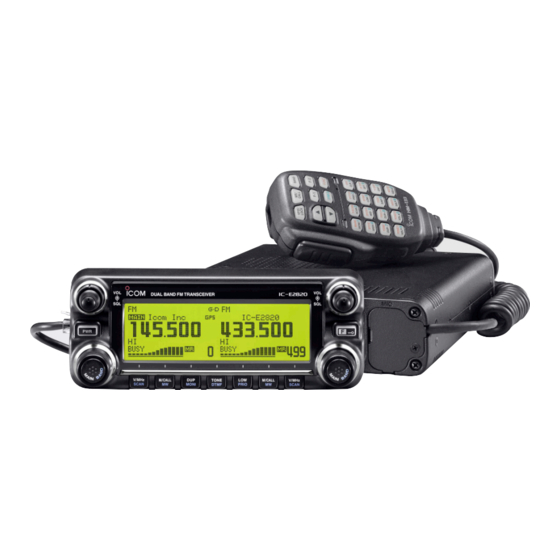
DUAL BAND FM TRANSCEIVER
iE2820
This device complies with Part 15 of the FCC Rules. Operation is sub-
ject to the following two conditions: (1) this device may not cause
harmful interference, and (2) this device must accept any interference
received, including interference that may cause undesired operation.
Advertisement
Table of Contents

Subscribe to Our Youtube Channel
Related Manuals for Icom IC-E2820


Summary of Contents for Icom IC-E2820
- Page 1 INSTRUCTION MANUAL DUAL BAND FM TRANSCEIVER iE2820 This device complies with Part 15 of the FCC Rules. Operation is sub- ject to the following two conditions: (1) this device may not cause harmful interference, and (2) this device must accept any interference received, including interference that may cause undesired operation.
-
Page 2: Foreword
IC-E2820. We want to take a couple of moments of your time to thank you for making your IC-E2820 your radio of choice, and hope you agree with Icom’s philosophy of “technology first.” Many EXPLICIT DEFINITIONS hours of research and development went into the design of your IC-E2820. -
Page 3: Precautions
If an incorrect connection is made after cutting, the transceiver when cleaning, as they can damage the transceiver’s surfaces. may be damaged. Icom microphones only (supplied or optional). Other manu- NEVER expose the transceiver to rain, snow or any liquids. The facturer’s microphones have different pin assignments and may dam-... -
Page 4: Supplied Accessories
SUPPLIED ACCESSORIES q DC power cable (3 m) ………………………………………1 w Controller cable (10 cm † ) ……………………………………1 e Separation cable (3.4 m ) …………………………………1 † r Magnets with screws ………………………………………2 t Fuse (20 A) …………………………………………………1 y Microphone hanger …………………………………………1 u Microphone (HM-133)* ……………………………………1 i Mounting screws, nuts and washers …………………1 set o Mobile mounting bracket …………………………………1... -
Page 5: Table Of Contents
TABLE OF CONTENTS FOREWORD ..................i 3 BASIC OPERATION ............20–28 ■ Receiving ................20 IMPORTANT ..................i ■ Transmitting ................20 EXPLICIT DEFINITIONS ..............i ■ Selecting output power ............21 PRECAUTIONS ................ii ■ Operating mode selection ............. 21 SUPPLIED ACCESSORIES ............ -
Page 6: Table Of Contents
TABLE OF CONTENTS ■ Break-in communication ............51 8 SCAN OPERATION ............73–78 ■ Message operation ............... 52 ■ Scan types ................73 ■ Automatic reply function ............55 ■ Scan start/stop ..............74 ■ EMR communication ............. 56 ■ Scan edges programming ............. 75 ■... - Page 7 13 MENU SCREEN OPERATION ......... 95–112 15 GPS/GPS-A OPERATION ..........121–128 ■ General ................. 95 ■ GPS operation ..............121 ■ Menu list ................96 ■ GPS-A operation ..............128 ■ Item list .................. 96 16 MAINTENANCE ............. 129–131 ■ SET MODE items ..............99 ■...
-
Page 8: Quick Reference Guide
QUICK REFERENCE GUIDE ■ Installation D Precaution— magnets D Installation methods RCAUTION Controller Magnets are used for the controller’s attachment to the main unit. NEVER hold the whole unit by the controller only when carry- ing the transceiver. Carry the transceiver holding the main unit. -
Page 9: Using The Mounting Bracket
AVOID placing the transceiver or remote controller in direct self-tapping sunlight. screws Flat washer Mounting nut Main unit 25˚ Controller Main unit IMPORTANT! Main unit Detailed installation notes for Icom mobile transceivers to fitted into vehicles are available. Contact your Icom dealer or distributor. -
Page 10: Microphone Connection
(10 cm) body installation and separation cable for remote in- panel. Connect the supplied microphone connector as illus- (3.4 m) stallation, are supplied with the IC-E2820. trated below. Controller Microphone Connect the controller and the main unit using with the sup- plied connection cable as follows. - Page 11 QUICK REFERENCE GUIDE D Optional GPS antenna connection D Important notes when using GPS receiver When the optional UT-123 is installed, the GPS antenna sup- • The GPS antenna is not weather-proof construction, there- plied with the UT-123 can be connected. fore, NEVER install the antenna in outdoor.
- Page 12 QUICK REFERENCE GUIDE D Controller’s attachment D Remote installation You can attach the controller of the IC-E2820 by one of 2 The supplied remote controller bracket is used for remote in- methods. stallation. • Attach the remote controller • Example 1...
- Page 13 QUICK REFERENCE GUIDE wAttach the remote controller on to the optional MB-65 as below. Adjust the view- angle Remote controller maximum visibili- bracket ty of the function display. Optional MB-65...
-
Page 14: Battery Connection
➥ DO NOT use the cigarette lighter socket for power con- nections. (See p. 10 for details) Use a rubber grommet when passing the DC power cable IC-E2820 through a metal plate to prevent a short circuit. − ⊕ black... -
Page 15: Dc Power Supply Connection
Use a 13.8 V DC power supply with at least 15 A capacity. Make sure the ground terminal of the DC power supply is grounded. • CONNECTING TO A DC POWER SUPPLY IC-E2820 DC power supply 13.8 V to an −... -
Page 16: Antenna Installation
QUICK REFERENCE GUIDE D Antenna installation • Antenna connector • Antenna location The antenna uses a PL-259 connector. To obtain maximum performance from the transceiver, select a high-quality antenna and mount it in a good location. It is • PL-259 CONNECTOR not necessary to use radials on a magnetic mount (“mag q Slide the coupling ring 30 mm... -
Page 17: Your First Contact
2. Selecting the main band The IC-E2820 displays 2 frequencies on the left and right Now that you have your IC-E2820 installed in your car or bands simultaneously. However, transmission, some keys shack, you are probably anxious to get on the air. We would and microphone operation apply only to the main band. - Page 18 3. Selecting the operating frequency band 4. Tune the frequency The IC-E2820 can use 2 m or 70 cm on either the left or right The tuning dial will allow you to dial in the frequency you want band. The operating band can be exchanged between them, to use.
-
Page 19: Repeater Operation
QUICK REFERENCE GUIDE ■ Repeater operation 1. Setting duplex Using the HM-133 Plus or minus duplex selection and the repeater tone setting Push the desired band’s [MAIN•BAND] to select the main can be made easily via the HM-133. band. Push [DUP•MONI] once or twice to select minus du- Push [ 7(TONE)] for minus duplex;... -
Page 20: Programming Memory Channels
QUICK REFERENCE GUIDE ■ Programming memory channels The IC-E2820 has a total of 522 memory channels (including 3. Writing a memory channel for storing often used operat- 20 scan edges and 2 call channels) Push and hold [S.MW](M/CALL•MW) for 1 sec. - Page 21 QUICK REFERENCE GUIDE Using the HM-133 q Push [MR/CALL] to select memory mode. wPush [ C(T-OFF)] first, then enter the desired memory channel via the keypad. ePush [VFO/LOCK] to select VFO mode, then set the de- sired operating frequency, including offset direction, tone settings, etc.
-
Page 22: Panel Description
PANEL DESCRIPTION ■ Front panel— controller Function display (pgs. 3–8) iE2820 DUAL BAND TRANSCEIVER V/MHz M/CALL TONE M/CALL V/MHz *The keys w to t are for SCAN MONI DTMF PRIO SCAN the MAIN band only. q POWER KEY [PWR] r TONE•DTMF KEY [TONE•DTMF] ➥... - Page 23 PANEL DESCRIPTION Left band Right band iE2820 DUAL BAND TRANSCEIVER V/MHz M/CALL TONE M/CALL V/MHz SCAN MONI DTMF PRIO SCAN *The same controls for both the left and right bands are arranged symmetrically. y SQUELCH CONTROL [SQL] !0 VFO/MHz TUNING•SCAN KEY [V/MHz•SCAN] ➥...
-
Page 24: Function Display
PANEL DESCRIPTION ■ Function display !7 !6 *The same indications for both the left and right bands are arranged. q OPERATING MODE INDICATOR r TONE INDICATOR (p. 21) ➥ During FM mode operation: Shows the selected operating mode. ● “TONE” appears while the repeater tone is in use. ●... - Page 25 PANEL DESCRIPTION ➥ During DV* o AUTO POWER OFF INDICATOR mode operation: (Digital) (p. 118) ● “DSQL” appears while the digital call sign squelch ● Appears when the auto power OFF function is in use. function is in use. (p. 90) !0 KEY LOCK INDICATOR (p.
- Page 26 PANEL DESCRIPTION ■ Function display— continued !7 !6 *The same indications for both the left and right bands are arranged. !6 S/RF INDICATORS !9 AUDIO MUTE INDICATOR ➥ Shows the relative signal strength while receiving sig- Appears when the audio mute or sub-band mute (p.
- Page 27 PANEL DESCRIPTION Function guide indications (pgs. 7, 8) @2 FREQUENCY MARKER (p. 27) Gap shows the selected frequency in the band scope. @3 CENTER FREQUENCY MARKER Dotted line shows the center frequency of the band scope. @4 BAND SCOPE INDICATOR When the band scope function is in use, shows the band conditions.
-
Page 28: Function Guide Indications
PANEL DESCRIPTION ■ Function guide indications r SCAN SKIP KEY [SKIP](TONE•DTMF) The function guide indicators allow you to simply using a wide (p. 78) variety of functions. In memory mode, push to select the scan skip condition for the selected memory channel. D Function guide •... - Page 29 PANEL DESCRIPTION D Function guide 2 D Function guide 3 The function guide 2 indicators appear only when the op- The function guide 3 indications appear only when the op- tional UT-123 is installed and DV mode is selected. tional UT-123 is installed and GPS function is set to ON. i CALL SIGN SELECT KEY [CS](V/MHz•SCAN) !4 DATA KEY [DATA](V/MHz•SCAN) (p.
-
Page 30: Main Unit
PANEL DESCRIPTION ■ Main unit e GPS ANTENNA CONNECTOR [GPS ANT] (p. IV) When the optional digital unit, UT-123, is installed, con- nects the GPS antenna supplied with the optional UT-123. rPACKET JACK [PACKET] (pgs. 118, 119) Connects a TNC , etc. - Page 31 PANEL DESCRIPTION i ANTENNA CONNECTOR [ANT2 RX] (p. IX) ANTENNA INFORMATION Connects a 50 Ω antenna with a PL-259 connector and a For radio communications, the antenna is of critical impor- 50 Ω coaxial cable for diversity reception. tance, to maximize your output power and receiver sensi- tivity.
-
Page 32: Microphone (Hm-133)
PANEL DESCRIPTION ■ Microphone (HM-133*) ➥ Push and hold either key for 1 sec. to start scanning. (p. 74) r ACTIVITY INDICATOR ➥ Lights red while any key, except [FUNC] and [DTMF-S], is pushed, or while transmitting. ➥ Lights green while the one-touch PTT function is in use. t KEYPAD Mic element (pgs. -
Page 33: Microphone Keypad
PANEL DESCRIPTION ■ Microphone keypad FUNCTION SECONDARY FUNCTION ( +key) OTHER FUNCTIONS Switches between opening and closing the In VFO mode enters operating band selec- squelch. tion. (p. 24) In memory mode enters bank selection. (p. 63) Starts and stops scanning. Starts and stops tone scanning. - Page 34 PANEL DESCRIPTION FUNCTION SECONDARY FUNCTION ( +key) OTHER FUNCTIONS ➥ Cancels frequency entry. ➥ Stores the set frequency, etc., into the (p. 17) ➥ Cancels the scan or priority watch. selected memory channel when pushed and held. (pgs. 74, 80) (p.
-
Page 35: Optional Microphones (Hm-154)
PANEL DESCRIPTION ■ Optional Microphone (HM-154) q PTT SWITCH Push and hold to transmit; release to receive. w UP/DOWN KEYS [UP]/[DN] ➥ Push either key to change operating frequency, mem- ory channel, set mode setting, etc. (pgs. 17, 60, 95) ➥... -
Page 36: Setting A Frequency
OFF. D MAIN band [DIAL] The IC-E2820 can receive 144 MHz and 430 MHz band sig- nals simultaneously. To change or activate any of the func- tions or to change frequency via the microphone, you must designate one band as the main band. The transceiver trans- mits a signal on the main band only. - Page 37 ✔ About extra frequency bands— depending on versions [M/CALL•MW] In addition to the 2 m and 70 cm ham bands, some versions of the the IC-E2820 have extra frequency bands for each left and right bands as follow. See the specifications for the available frequency bands for details.
-
Page 38: Using The Tuning Dial
SETTING A FREQUENCY ■ Using the tuning dial ■ Using the keypad The frequency can be directly set via numeral keys on the mi- q Rotate the desired band’s [DIAL] to set the frequency. crophone. • If VFO mode is not selected, push the same band’s [V/MHz•SCAN] to select VFO mode. -
Page 39: Tuning Step Selection
SETTING A FREQUENCY ■ Tuning step selection ePush [TS](M/CALL•MW) (Left band’s) to enter tuning step Tuning steps are the minimum frequency change increments when you rotate [DIAL] or push [Y]/[Z] on the microphone. set mode. Independent tuning steps for the left and right bands, as well as each frequency band can be set for individual tuning con- venience. -
Page 40: Lock Functions
SETTING A FREQUENCY ■ Lock functions D Microphone keypad lock To prevent accidental frequency changes and unnecessary function access, use the lock function. The transceiver has 2 This function locks the microphone keypad. different lock functions. ➥ Push [FUNC] then [ D(16KEY-L)] to turn D Frequency lock 16KEY-L... -
Page 41: Basic Operation
IMPORTANT! (for 50 W transmission): SQLY/Z Y(TONE-1)]/[ Z 0(TONE-2)] be adjusted with [ The IC-E2820 is equipped with protection circuits to protect and [ D(MUTE)]/[ #(16KEY-L)], respectively. the power amplifier circuit from high temperature. When the • “VOL” for audio or “SQL” for squelch appears during set. -
Page 42: Selecting Output Power
BASIC OPERATION ■ Selecting output power ■ Operating mode selection The transceiver has 3 output power levels to suit your oper- Operating modes are determined by the modulation of the ating requirements. Low output powers during short-distance radio signals. The transceiver has total 5 operating modes communications may reduce the possibility of interference to . -
Page 43: Squelch Attenuator
BASIC OPERATION ■ Squelch attenuator D Squelch attenuator setting The transceiver has an RF attenuator related to the squelch q Push [F• level setting. Approx. 10 dB attenuation is obtained at maxi- ] to display the function guide. wPush [MENU](V/MHz•SCAN) mum setting. -
Page 44: V/V, U/U Simultaneous Receive (Para-Watch)
BASIC OPERATION ■ V/V, U/U simultaneous receive (Para-watch) The IC-E2820 can simultaneously receive two signals on the To activate the para-watch function from the HM-133, enter same band, such as 144 MHz band, using the para-watch the desired frequencies for each the left and right bands using function. -
Page 45: Sub-Band Mute/Busy Beep
BASIC OPERATION ■ Sub-band mute/busy beep ■ Monitor function The sub-band mute function automatically cuts out sub-band This function is used to listen to weak signals without disturb- audio signals when both main and sub-band signals are re- ing the squelch setting. ceived simultaneously. -
Page 46: Single Band Operation
D D Diversity operation Dualwatch operation monitors two frequencies simultane- Diversity receiving compares the receiving signal strength ously. The IC-E2820 has two independent receiver circuits: from two different antennas, [ANT1 TX/RX] and [ANT2 RX], left band, and right band and automatically selects the strongest signal. This feature is... -
Page 47: One-Touch Ptt Function
BASIC OPERATION ■ One-touch PTT function The PTT switch can be operated as a one-touch PTT switch (each push toggles between transmit/receive). Using this When diversity operation is in use, connect the same type function you can transmit without pushing and holding the antenna to both [ANT1] and [ANT2 RX]. -
Page 48: Audio Mute Function
BASIC OPERATION ■ Audio mute function ■ Band scope This function temporarily mutes the audio without disturbing The band scope function allows you to visually check a spec- the volume setting. (microphone only) ified frequency range around the center frequency. ➥... - Page 49 BASIC OPERATION D D Single sweep D D Monitoring a signal q Set the desired frequency as band scope center frequency. If you find a signal that you want to monitor during/after w Push [F• ] to display the function guide. sweep, you can monitor the signal with the following opera- ePush [SCP](DUP•MONI) to start a single sweep.
-
Page 50: Repeater Operation
REPEATER OPERATION ■ General • Repeater operation flow chart Repeaters allow you to extend the operational range of your Step 1: radio because a repeater has much higher output power than Set the desired band to operate the repeater. the typical transceiver. Normally, a repeater has independent frequencies for each Step 2: receiver and transmitter. -
Page 51: Accessing A Repeater
REPEATER OPERATION ■ Accessing a repeater qSet the receive frequency (repeater output frequency) on r Push and hold [PTT] to transmit. • The displayed frequency automatically changes to the transmit the main band. (pgs. 15–17) frequency (repeater input frequency). wPush [DUP•MONI] one or two times, to select minus du- •... - Page 52 REPEATER OPERATION z Set the receive frequency m Push [ 9(TSQL)] to return to simplex opera- (repeater output fre- SIMP DUP– SIMP on the main band. tion. quency) (pgs. 16, 17) x Push [ • “DUP+” or “DUP–” indicator disappears. –...
-
Page 53: Subaudible Tones
REPEATER OPERATION ■ Subaudible tones (Encoder function) D Subaudible tones z Set the main band, mode/channel you wish to qSelect the main band, mode/channel you wish to set the set the subaudible tones for, such as VFO mode or memory/call channel. subaudible tones to, such as VFO mode or memory/call •... - Page 54 REPEATER OPERATION D DTMF tones D 1750 Hz tone ➥ Push [DTMF-S], then push the keys of the de- The microphone has 1750 Hz tone capability, used for ring DTMF-S sired DTMF digits. tone when calling, etc. • The function indicator lights green. •...
-
Page 55: Offset Frequency
REPEATER OPERATION ■ Offset frequency z Push [BAND] to select the desired band When communicating through a repeater, the transmit fre- (left or quency is shifted from the receive frequency by an amount as the main band. right) determined by the offset frequency. •... -
Page 56: Dv Mode Operation (Optional Ut-123 Is Required)
■ Digital mode operation ■ Call sign programming The IC-E2820 can be operated in digital voice mode and low- Four types of call sign memories are available: your own call speed data operation for both transmit and receive when the sign “MY CALL SIGN,”... - Page 57 DV MODE OPERATION (Optional UT-123 is required) D D Your own call sign programming u Repeat step y until your own call sign is programmed. Your own call sign must be programmed for both digital voice and low-speed data communications (including GPS transmis- sion) q Push [F•...
- Page 58 DV MODE OPERATION (Optional UT-123 is required) D D Station call sign programming uRepeat step y until the desired station call sign is pro- Station call signs must be programmed for the specified sta- grammed. tion call as well as repeater operation in all digital voice, low- speed data and GPS communications.
-
Page 59: Digital Voice Mode Operation
DV MODE OPERATION (Optional UT-123 is required) ■ Digital voice mode operation qSet the desired band as the main band. NOTE: The digital mode operation is vastly different from (Left or Right) (p. 15) • Select output power, if desired. (p. 21) FM mode. - Page 60 DV MODE OPERATION (Optional UT-123 is required) D D When calling the desired station ✔ For your information! Continued instruction from step v on page 38. Your own call sign, Station call sign and repeater call (MY) bRotate [DIAL] to select “YOUR,” then push [MAIN•BAND]. sign can also be programmed/edited in “CALL SIGN”...
-
Page 61: Dv Automatic Detect
NOTE: The received FM audio may be distorted when re- ceived during DV mode operation. ceiving an FM signal with the DV automatic detect function The IC-E2820 DV automatic detection monitors in FM mode active. when other than DV mode signal is received. -
Page 62: About D-Star System
DV MODE OPERATION (Optional UT-123 is required) ■ About D-STAR system In the D-STAR system, repeater linking via a 10 GHz band For current repeater operation, stations that are communicat- backbone and internet network (gateway connection) capa- ing must both be in the same repeater’s operating area. bilities are available. -
Page 63: Digital Repeater Operation
DV MODE OPERATION (Optional UT-123 is required) ■ Digital repeater operation yRotate [DIAL] to select the desired character, then push Repeater call signs must be programmed for repeater opera- tion in both digital voice and low-speed data communications. [>](M/CALL•MW) to move the cursor right. (Left band’s) •... - Page 64 DV MODE OPERATION (Optional UT-123 is required) D D Repeater operation in the same zone mPush [BACK](V/MHz•SCAN) qSet the desired repeater’s frequency, offset and shift direc- to exit “CALL (Right band’s) SIGN” screen. tion in the main band. (pgs. 30, 31) t Push [PTT] to transmit;...
- Page 65 DV MODE OPERATION (Optional UT-123 is required) • Setting example 1 Zone Area 1 Repeater 1 Area 2 Repeater 2 Area 3 Repeater 3 Area 4 Repeater 4 : A11111 : A22222 (Gateway) : A33333 : A44444 Station A Station C : A2222A Station B : A4444C...
- Page 66 DV MODE OPERATION (Optional UT-123 is required) D D Repeater operation into another zone bRotate qSet the desired repeater’s frequency, offset and shift direc- select “RPT2” then push [DIAL] [MAIN•BAND]. tion in the main band. (pgs. 30, 31) • RPT2 CALL SIGN screen is displayed. •...
- Page 67 DV MODE OPERATION (Optional UT-123 is required) • Setting examle 2 Zone A Area 1 Repeater 1 Area 2 Repeater 2 Area 3 Repeater 3 Area 4 Repeater 4 : A11111 : A22222 (Gateway) : A33333 : A44444 Station A Station B : A2222A Internet...
-
Page 68: Received Call Sign
DV MODE OPERATION (Optional UT-123 is required) ■ Received call sign ePush [MAIN•BAND] to display the received call details. When a call is received in DV mode, the calling station and • CALLER : The station call sign that made a call. the repeater call signs being used can be stored into the re- •... - Page 69 DV MODE OPERATION (Optional UT-123 is required) D D One-touch reply qAfter receiving a call, push [F• ] twice to display the NOTE: • Set your own call sign (MY) in advance. function guide 2. (p. 39) wPush [R>CS](TONE•DTMF) to set the received call sign as •...
-
Page 70: Copying The Call Sign
DV MODE OPERATION (Optional UT-123 is required) ■ Copying the call sign D D Copying the call sign memory contents This function is convenient when modifying part of the current call sign. NOTE: Make sure that the “EDIT RECORD” item in DV set mode is set to “AUTO”... - Page 71 DV MODE OPERATION (Optional UT-123 is required) D D Copying the call record contents into call • When “CALLER,” “RXRPT1” or “RXRPT2” is selected sign memory zPush [MAIN•BAND] then rotate [DIAL] to select the de- This is a way to copy the call record contents (“CALLER,”...
-
Page 72: Break-In Communication
DV MODE OPERATION (Optional UT-123 is required) ■ Break-in communication yWhen both stations are in standby, push [PTT] to transmit a break-in call. The break-in function allows you to break into a conversation, • The programmed call sign station receives the break-in call as well as your call sign. -
Page 73: Message Operation
DV MODE OPERATION (Optional UT-123 is required) ■ Message operation D D TX message programming TX messages are available for up to 5 channels, and each channel can be programmed with a message of up to 20 characters. Available characters are 0 to 9, A to Z (capital let- , a to z , some symbols and space. - Page 74 [BACK](V/MHz•SCAN) again to return (Right band’s) NOTE: Only 1 message can be stored in the IC-E2820. to function guide 2 indication. The received message is cleared by turning power OFF, uPush [PTT] to transmit the selected message.
- Page 75 DV MODE OPERATION (Optional UT-123 is required) D D RX message indication ➥ Via function guide 2 The received message can also be checked via MENU screen and function guide 2. q Push [F• ] twice to display the function guide 2. wPush [MSG](LOW•PRIO) to display the “MESSAGE”...
-
Page 76: Automatic Reply Function
DV MODE OPERATION (Optional UT-123 is required) ■ Automatic reply function D D Voice memory recording for automatic reply IMPORTANT! The automatic reply function replies to calls by a station that Set the transceiver for single band operation and/or set mini- specified your call sign. -
Page 77: Emr Communication
DV MODE OPERATION (Optional UT-123 is required) ■ EMR communication D D Play-back or erase the voice memory q Push [F• ] to display the function guide. The EMR communication mode is available for digital mode wPush [MENU](V/MHz•SCAN) to display the (Right band’s) operation. -
Page 78: Low-Speed Data Communication
(purchase locally) follows. quired in addition. • Port : The same COM port number as IC-E2820’s NOTE: Turn OFF the GPS data communication (p. 127) • Baud rate : 9600 bps (fixed value) advance to operate the low-speed data communication. -
Page 79: Dv Voice Memory
DV MODE OPERATION (Optional UT-123 is required) ■ DV voice memory D D Transmission condition setting The IC-E2820 has a DV voice memory that records a total of 30 sec. (approx.) of received audio. q Push [F• ] to display the function guide. - Page 80 DV MODE OPERATION (Optional UT-123 is required) ◆ Track size setting ◆ Playing-back and erasing the recorded audio The track size can be changed with the following instruction. qPush [F• ] twice to display the function guide 2. wPush [REC](M/CALL•MW) to enter REC track (Right band’s) qPush [F•...
-
Page 81: Memory Mode Operation
MEMORY MODE OPERATION ■ General description D Using the [Y]/[Z] keys The transceiver has 522 memory channels, including 20 scan edge memory channels (10-pairs) and 2 call channels. Each z Push [BAND] to select the desired band as of these channels can be individually programmed with oper- MR/CALL the main band. -
Page 82: Programming A Memory Channel
MEMORY MODE OPERATION ■ Programming a memory channel VFO settings, including MENU group contents such as sub- eRotate the [DIAL] to select the memory channel to be pro- audible tone frequency and offset can be programmed into a grammed. memory channel. •... - Page 83 MEMORY MODE OPERATION D Programming a memory channel via the microphone The microphone can also be used to program mem- ory channels. z Set the desired frequency in VFO mode. v Push [VFO/LOCK] to select VFO mode. ➥ Push [VFO/LOCK] to select VFO mode. b Push [FUNC] then push and hold [ A(MW)] for 1 sec.
-
Page 84: Memory Bank Selection
MEMORY MODE OPERATION ■ Memory bank selection z Push [MR/CALL] to select memory mode, if de- The IC-E2820 has a total of 26 banks . All memory (A to Z) BANK sired. channels, regular channels, scan edges and call channels are... -
Page 85: Memory Bank Setting
MEMORY MODE OPERATION ■ Memory bank setting qPush the desired band’s [M/CALL•MW] several times to uPush [BACK](V/MHz•SCAN) to set the bank (Right band’s) select memory mode, then rotate the same band’s [DIAL] initial and channel number. to select the desired memory channel. •... -
Page 86: Programming Memory/Bank/Scan Name
MEMORY MODE OPERATION ■ Programming memory/bank/scan name Each memory channel can be programmed with an alphanu- • Push [1/](M/CALL•MW) to select the character (Right band’s) meric channel name for easy recognition and can be indi- group from numbers or symbols. cated independently by channel. - Page 87 MEMORY MODE OPERATION [EXAMPLE]: Programming the bank name “AIR” into the scan edge channel 3A. Memory mode M/CALL Push (Main band’s) to select memory mode. V/MHz Push (Main band’s) several times SCAN to select “B NAME”. EDIT M/CALL Push (Right band’s) to enter bank name edit mode.
-
Page 88: Copying Memory Contents
MEMORY MODE OPERATION ■ Copying memory contents This function copies a memory channel’s contents to VFO . This is useful when searching for another memory/call channel) signals around a memory channel frequency and for recall- ing the offset frequency, subaudible tone frequency etc. z Push [BAND] to select the desired band as MR/CALL the main band, if necessary. - Page 89 MEMORY MODE OPERATION D Memory/call➪call/memory q Select the memory/call channel to be copied. ➥ Push the desired band’s [M/CALL•MW] several times to select memory mode or call channel, then rotate the same band’s [DIAL] to select the desired memory or call channel.
-
Page 90: Memory Clearing
MEMORY MODE OPERATION ■ Memory clearing Contents of programmed memories can be cleared (blanked), if desired. qPush [V/MHz•SCAN] to select VFO mode in the desired tPush [BACK](V/MHz•SCAN) to return to VFO (Right band’s) band mode. (left or right) wPush and hold the same band’s [M/CALL•MW] for 1 sec. NOTE: Be careful!—... -
Page 91: Erasing/Transferring Bank Contents
MEMORY MODE OPERATION ■ Erasing/transferring bank contents Contents of programmed memory banks can be cleared or rRotate [DIAL] to select the desired bank initial (A to Z) transferred to another bank. transfer. • Select no indication, “– – – –,” when erasing the contents from INFORMATION: Even if the memory bank contents are the bank. -
Page 92: Call Channel Operation
CALL CHANNEL OPERATION ■ Call channel selection ■ Call channel copying D Call➪VFO/Memory Call channel is a pre-programmed memory channel that can be accessed by simply pushing call channel button. qPush the desired band’s [M/CALL•MW] several times to select call channel mode, then rotate the same band’s ➥... -
Page 93: Programming A Call Channel
CALL CHANNEL OPERATION ■ Programming a call channel rPush the same band’s [M/CALL•MW] for 1 sec. to pro- Operating frequency, duplex information, subaudible tone in- formation gram. (tone encoder or tone squelch ON/OFF and its frequency) • 3 beeps sound and the unit returns to VFO mode automatically. can be programmed into the call channel. -
Page 94: Scan Operation
SCAN OPERATION ■ Scan types Scanning searches for signals automatically and makes it There are 4 scan types and 4 resume conditions to suit your easier to locate new stations for contact or listening purposes. operating needs. Repeatedly scans all frequen- Repeatedly scans memory FULL SCAN MEMORY (SKIP) SCAN... -
Page 95: Scan Start/Stop
SCAN OPERATION ■ Scan start/stop D Preparation tTo stop the scan, push the same band’s [V/MHz•SCAN]. Scan resume condition ; program the scan edges (p. 77) ; program 2 or more memory channels (pgs. 75, 76) (pgs. 61, z Push [VFO/LOCK] to select VFO mode for ;... -
Page 96: Scan Edges Programming
SCAN OPERATION ■ Scan edges programming rPush and hold [S.MW](M/CALL•MW) Scan edges can be programmed in the same manner as for 1 sec. (Left band’s) memory channels. Scan edges are programmed into scan to program. • 3 beeps sound and VFO is automatically selected. edges, 0A/0B to 9A/9B, in memory channels. - Page 97 SCAN OPERATION D Programming scan edges via microphone z Push [MR/CALL] to select memory mode. v Push [FUNC], then push and hold [ A(MW)] for 1 sec. x Select scan edge channel, 0A to9A using [Y]/[Z] to program. or keypad. •...
-
Page 98: Scan Resume Condition
SCAN OPERATION ■ Scan resume condition z Push [BAND] to select the desired band The scan resume condition can be selected as timer or pause (left or scan. The selected resume condition is also used for priority as the main band. right) x Push [ watch. -
Page 99: Skip Channel Setting
SCAN OPERATION ■ Skip channel setting The memory skip function speeds up scanning by checking only those memory channels not set as skip channels. Set skip channels as follows. Skip indicator appears q Select a memory channel in the desired band (Left or Right) ➥... -
Page 100: Priority Watch
PRIORITY WATCH ■ Priority watch types Priority watch checks for signals on a VFO frequency every MEMORY CHANNEL WATCH 5 sec. while operating in memory mode. The transceiver has While operating on a VFO fre- 3 priority watch types to suit your needs. You can also trans- 5 sec. -
Page 101: Priority Watch Operation
PRIORITY WATCH ■ Priority watch operation qSelect VFO mode, then set an operating frequency in the z Select VFO mode; then, set the desired fre- PRIO desired MAIN band quency. (left or right) w Set the watched channel(s). x Set the watched channel(s). For memory channel watch: For memory channel watch: Select the desired memory channel. -
Page 102: Dtmf Memory Encoder
DTMF MEMORY ENCODER ■ Programming a DTMF tone sequence DTMF tone sequences are used for autopatching, controlling other equipment, etc. The transceiver has 16 DTMF memory channels (d0–d#) for storage of often-used DTMF tone se- quences of up to 24 digits. t Push [>](M/CALL•MW) to select the next digit. -
Page 103: Transmitting A Dtmf Tone Sequence
DTMF MEMORY ENCODER ■ Transmitting a DTMF tone sequence D Automatic transmission (DTMF memory) z Push [FUNC] then [ 6(DTMF)] to turn the qPush and hold [TONE•DTMF] for 1 sec. to enter DTMF set DTMF DTMF memory encoder ON. mode. ☎... - Page 104 DTMF MEMORY ENCODER D Transmitting a DTMF memory directly D Manual transmission z Push [FUNC] then [ z Deactivate the DTMF memory encoder by 6(DTMF)] to turn the DTMF-S DTMF-S DTMF memory encoder ON. pushing [FUNC] then [ B(D-OFF)]. ☎ x Push [DTMF-S] to turn the DTMF direct selec- •...
-
Page 105: Dtmf Speed
DTMF MEMORY ENCODER ■ DTMF speed The rate at which DTMF values in memory send individual DTMF characters can be set to accommodate operating needs. q Push [F• ] to display the function guide. wPush [MENU](V/MHz•SCAN) to enter MENU (Right band’s) screen. -
Page 106: Tone Squelch And Pocket Beep
TONE SQUELCH AND POCKET BEEP ■ Tone/DTCS squelch beep operation qSet the desired operating frequency and the desired oper- z Set the operating frequency. TSQLS x Push [FUNC] then push one of following keys ating mode. wSet the desired CTCSS tone or DTCS code. to turn the desired squelch system ON. - Page 107 TONE SQUELCH AND POCKET BEEP D Reverse tone/DTCS squelch D Setting tone squelch frequency q Push [F• The reverse tone/DTCS squelch is convenient if you want to ] to display the function guide. w Push [MENU](V/MHz•SCAN) ignore a specific signal. to enter MENU (Right band’s) screen.
- Page 108 TONE SQUELCH AND POCKET BEEP D Setting DTCS code z Push [ q Push [F• B(D-OFF)] to enter set mode. ] to display the function guide. x Push w Push [MENU](V/MHz•SCAN) [Y]/[Z] several times select to enter MENU (Right band’s) “DUP/TONE…”...
-
Page 109: Dtcs Polarity Setting
TONE SQUELCH AND POCKET BEEP ■ DTCS polarity setting q Push [F• z Push [ ] to display the function guide. B(D-OFF)] to enter set mode. w Push [MENU](V/MHz•SCAN) x Push to enter MENU [Y]/[Z] several times select (Right band’s) screen. -
Page 110: Tone Scan
TONE SQUELCH AND POCKET BEEP ■ Tone scan yWhen the CTCSS tone frequency or 3-digit DTCS code is matched, the squelch opens and the tone frequency is By monitoring a signal that is being operated with pocket temporarily programmed into the selected feature, such as beep, tone or DTCS squelch function, you can determine the memory or call channel. -
Page 111: Digital Call Sign/Digital Code Squelch
TONE SQUELCH AND POCKET BEEP ■ Digital call sign/digital code squelch The optional UT-123 D D YOUR and MY call signs setting NOTE: Use digital code squelch when operating with two or more stations. Because the digital call sign squelch function See page 38 for DV MODE OPERATION. -
Page 112: Pager/Code Squelch
PAGER/CODE SQUELCH ■ Pager function ■ Code programming D D Before programming This function uses DTMF codes for paging and can be used as a “message pager” to confirm you of a caller’s identification The pager and code squelch functions require ID codes and a even when you leave the transceiver temporarily unattended. - Page 113 PAGER/CODE SQUELCH D D Code programming !0 Enter the desired 3-digit transmit code as described in Your ID code MUST be programmed into code channel C0. steps u and i. Up to 5 transmit codes (codes that you transmit) are pro- !1 Push [SKIP](V/MHz•SCAN) to set the channel grammable into code channels, C1 to C5, if required.
-
Page 114: Pager Operation
PAGER/CODE SQUELCH ■ Pager operation D Calling a specific station o Push [PTT] to transmit the pager code. !0 Wait for an answer back. q Program the pager code channel in advance (p. 92) • When the transceiver receives an answer back code, the func- w Set the operating frequency. -
Page 115: Code Squelch
PAGER/CODE SQUELCH ■ Code squelch • PERSONAL CALLS This display appears when you are called with your ID code When using code squelch you will only receive calls from sta- and the calling station’s ID code is 444. tions which know your ID or group code. A 3-digit code is sent “PGR”... -
Page 116: Menu Screen Operation
MENU SCREEN OPERATION ■ General z Push [ MENU screen is used for programming infrequently changed B(D-OFF)] to enter MENU screen. x Push [Y] or [Z] to select the desired menu group, values or conditions of functions. then push [ B(D-OFF)] to enter the appropri- •... -
Page 117: Menu List
MENU SCREEN OPERATION ■ Menu list ■ Items list D D CALL SIGN MEMORY † ITEMS REF. ITEMS REF. ITEMS REF. ITEMS REF. † CALL SIGN MEMORY — DUP/TONE... p. 104 — — † YOUR CALL SIGN MEMORY MY CALL SIGN MEMORY RX CALL SIGN —... - Page 118 MENU SCREEN OPERATION D D SET MODE D D SCAN ITEMS REF. ITEMS REF. ITEMS REF. ITEMS REF. TIME-OUT TIMER p. 99 AUTO ATT p. 100 p. 103 p. 103 SCAN TIMER BANK LINK SCAN AUTO POWER OFF p. 99 p.
- Page 119 MENU SCREEN OPERATION D D GPS-A SET MODE D D SOUNDS ITEMS REF. ITEMS REF. ITEMS REF. ITEMS REF. UNPROTO ADDRESS p. 111 GPS-A SYMBOL p. 111 KEY-TOUCH BEEP p. 107 SUB BAND MUTE p. 107 DATA EXTENSION p. 111 COMMENT p.
-
Page 120: Set Mode Items
MENU SCREEN OPERATION ■ SET MODE items D D Time-out timer D D PTT lock To prevent accidental prolonged transmission, etc., the trans- Turns the PTT lock function ON and OFF (default) ceiver has a time-out timer. This function cuts a transmission Transmission with [PTT] is inhibited when ON is selected to OFF after 3, 5, 15 or 30 min. - Page 121 MENU SCREEN OPERATION D D Squelch delay D D Diversity Selects squelch delay from short and long to prevent re- Turns the diversity function ON and OFF (default) peated opening and closing of the squelch during reception of the same signal. D D GPS •...
-
Page 122: Dv Set Mode Items
■ DV SET MODE items D D Digital monitor The following items are selectable by optional UT-123 is in- stalled into the IC-E2820. Sets the desired monitoring mode during DV mode operation from “AUTO,” “DIGITAL” and “ANALOG.” D D Auto reply •... - Page 123 MENU SCREEN OPERATION D D Repeater call sign auto write D D Call sign edit record When accessing a repeater with a call sign that is different Selects the call sign programming when the call sign is edited than the one programmed in your radio, the repeater call sign or corrected with the pre-programmed call sign via call sign can be set into “RPT1”...
-
Page 124: Scan Items
MENU SCREEN OPERATION ■ SCAN items D D Scan timer D D Bank link scan Selects scan resume timer from T-15 , T-10, T-5 and Sets the memory bank link function ON and OFF . The (default) (default) P-2. link function provides continuous bank scan, scanning all con- •... -
Page 125: Dup/Tone Items
MENU SCREEN OPERATION ■ DUP/ TONE items D D Offset frequency D D DTCS code Sets the duplex offset frequency from 0 to 159.995 MHz. Dur- Sets DTCS code for DTCS squelch (both encoder and decoder) ing duplex (repeater) operation, transmit frequency shifts the operation. -
Page 126: Display Items
MENU SCREEN OPERATION ■ DISPLAY items D D PGR/C-SQL D D Backlight Sets pager or code squelch function ON (“PGR” for pager Sets backlighting color conditions. The color can be changed function ON; “C-SQL” for code squelch function ON) and between red and green in 20 steps. - Page 127 ☞ Available only when the UT-123 is installed. The opening logo indication (Icom logo and transceiver name) When a call is received, the calling station call sign can be in- that is displayed at power ON can be skipped, if desired.
-
Page 128: Sound Items
MENU SCREEN OPERATION ■ SOUND items D D Key-touch beep D D Sub-band beep The key-touch beep can be turned OFF for silent operation. Turns the sub-band busy beep function capability ON and (default: ON) (default) D D Beep level D D Standby Beep ☞... -
Page 129: Dv Gps Items
MENU SCREEN OPERATION ■ DV GPS items D D GPS sentence D D RX GPS message q Enter MENU screen via function guide. Shows the received GPS message. ➥ Push [F• ] to display function guide. See p. 126 in chapter 15 for details. ➥... -
Page 130: Packet Items
MENU SCREEN OPERATION ■ PACKET items ■ GPS SET MODE items D D Packet BPS D D GPS SPEED Selects the data transmission speed for packet operation Selects the data transmission speed for packet operation from 1200 bps and 9600 bps. from 4800 bps and 9600 bps. - Page 131 MENU SCREEN OPERATION D D Alarm area 1 D D Alarm area 2 Sets GPS alarm active range within 00′05″ to 59′59″ in 1 sec. Selects GPS alarm active range from “LIMITED,” “EX- steps. TENDED” and “BOTH.” (00′01″) (default: 00′15″) •...
-
Page 132: Gps-A Set Mode Items
MENU SCREEN OPERATION ■ GPS-A SET MODE items D D Unproto address D D Data extension Sets up to 56-character unproto address. Sets the data extension capability from “COURSE/SPEED” and OFF (default) q Push [MAIN•BAND] to enter programming condition. The transceiver’s course and speed information is addition- wRotate [DIAL] to select the desired character. -
Page 133: Menu Screen Operation
MENU SCREEN OPERATION D D GPS-A symbol D D Comment Selects the desired GPS-A symbol. Program up to a 43-character* comment. The programmed comment is transmitted with the GPS position data. Available symbols: Ambulance, Bus, Fire Truck, Bicycle, *36-character comment only programmed when... -
Page 134: Other Functions
OTHER FUNCTIONS ■ Microphone keys ➥ Programming the main band condition The supplied HM-133’s [F-1] and [F- (optional for some versions) 2] keys memorize the transceiver conditions. [F-1]/[F-2] Set the desired contents of each condition in The [UP]/[DN] keys of the standard or an optional microphone the main band, then push [F-1]/[F-2] for 1 sec. -
Page 135: All Reset
OTHER FUNCTIONS ■ All reset ■ Partial reset POWER ON POWER ON The function display may occasionally display erroneous in- If you want to initialize the operating conditions (VFO frequency, formation . This may be caused without clearing the mem- (e.g. -
Page 136: Data Cloning
OTHER FUNCTIONS ■ Data cloning POWER ON wWhile pushing right band’s [M/CALL•MW], turn power ON Cloning allows you to quickly and easily transfer the pro- grammed contents from one transceiver to another; or, data to enter cloning mode (master transceiver only— power on only from a personal computer to a transceiver using the optional for sub-transceiver) •... -
Page 137: Auto Power Off
OTHER FUNCTIONS ■ Auto power OFF D Cloning using a personal computer The transceiver can be set to automatically turn OFF after a specified period with a beep when no switch is pushed. Data can be cloned to and from a personal computer (Mi- crosoft Windows 98SE/2000/Me/XP) using the optional CS-... -
Page 138: Packet Operation
OTHER FUNCTIONS ■ Packet operation D Data speed DPACKET JACK PIN ASSIGNMENT For packet operation, the transceiver can be set to one of two data speeds: 1200 bps or 9600 bps. (default) q Push [F• ] to display function guide. w Push [MENU](V/MHz•SCAN) to enter MENU (Right band’s) - Page 139 OTHER FUNCTIONS D 1200 bps packet operation q Connect the transceiver and a TNC as illustrated below. • Read the instructions supplied with your TNC carefully before attempting packet operation with the transceiver. TNC side • Pin t AF OUT is for 1200 bps operation only. This pin q DATA IN TX AUDIO cannot be used for 9600 bps operation.
- Page 140 OTHER FUNCTIONS D 9600 bps high speed packet operation • When using the PTT P terminal for packet operation, no The transceiver supports 2 modes of 9600 bps packet opera- voice signals are transmitted from the microphone. tion: G3RUH and GMSK. •...
-
Page 141: Other Functions
OTHER FUNCTIONS D Adjusting the transmit signal output from D Packet operation band selection Both bands, or either the left or right band only, can be spec- the TNC ified for packet operation to suit your preference. When setting data transmission speed to 9600 bps, the data signal coming from the TNC is applied exclusively to the in- q Push [F•... -
Page 142: Gps/Gps-A Operation
GPS/GPS-A OPERATION ■ GPS operation D D GPS function A GPS receiver is built-in to the optional UT-123. When UT- 123 is installed, GPS operation that indicate the current posi- qWhile in DV mode operation, push [F• ] to display the tion (Latitude and Longitude) and time is available. - Page 143 GPS/GPS-A OPERATION D D Sentence formatters selection y Push [BACK](V/MHz•SCAN) q Enter MENU screen via function guide. twice to return to (Right band’s) ➥ Push [F• frequency indication. ] to display function guide. ➥ Push [MENU](V/MHz•SCAN) • “GPS” indicator stays ON when GPS signal is received, or blinks to enter (Right band’s) when GPS signal cannot be received.
- Page 144 GPS/GPS-A OPERATION D D Position indication D D GPS Automatic transmission q Enter MENU screen via function guide. q Push [F• ] several times to display function guide 3. ➥ Push [F• ] to display function guide. w Push [POSI](M/CALL•MW) once to display the (Left band’s) ➥...
- Page 145 GPS/GPS-A OPERATION D D GPS message programming o Rotate [DIAL] to select “GPS AUTO TX,” then push q Enter MENU screen via function guide. ➥ Push [F• [MAIN•BAND] to enter GPS auto transmission interval. ] to display function guide. ➥ Push [MENU](V/MHz•SCAN) to enter (Right band’s) MENU screen.
- Page 146 GPS/GPS-A OPERATION D D Receiving a GPS transmission tRotate [DIAL] to select the desired character. qWhile in DV mode operation, push [F• ] three times to • Push [Aa](TONE•DTMF) to select the character group from cap- display function guide 3. w Push [POSI](M/CALL•MW) ital letters or lower case letters.
- Page 147 GPS/GPS-A OPERATION D D RX GPS message indication D D Programming GPS memory q Enter MENU screen via function guide. Each memory channel can be programmed with an alphanu- ➥ Push [F• ] to display function guide. meric channel name for easy recognition and can be dis- ➥...
- Page 148 GPS/GPS-A OPERATION D D GPS alarm setting D D GPS memory clearing qPush [GMR](TONE•DTMF) to select GPS memory mode. GPS alarm sounds when your own position is close the spec- wRotate [DIAL] to select “ALL,” or desired memory bank, ified area. This function can be set the received channel, then push [MAIN•BAND].
-
Page 149: Gps-A Operation
GPS/GPS-A OPERATION ■ GPS-A operation D D GPS-A function D D GPS-A code details Set the following for activate the GPS-A function. While in GPS-A operation, following codes are transmitted to qSelect the DV mode operation (p. 38) ® your connecting PC. GPS-A code is based on APRS code. -
Page 150: Maintenance
MAINTENANCE ■ Troubleshooting If your transceiver seems to be malfunctioning, please check the following points before sending it to a service center. PROBLEM POSSIBLE CAUSE SOLUTION REF. Does not turn on. • Power connector has a poor contact. • Check the connector pins. —... -
Page 151: Fuse Replacement
MAINTENANCE PROBLEM POSSIBLE CAUSE SOLUTION REF. Some memory channels • The memory channel number has not yet been • Select the channel via the microphone keypad to — cannot be selected via the programmed. check whether the channel has been programmed tuning dial. -
Page 152: Optional Ut-123 Installation
MAINTENANCE ■ Optional UT-123 installation w Insert the UT-123 into the connector on the main unit as il- IMPORTANT! lustrated as below, then confirm to install it completely. Turn power OFF and disconnect the transceiver from power source before opening the top cover. Otherwise an electric shock or damage to the transceiver may occur. -
Page 153: Specifications And Options
SPECIFICATIONS AND OPTIONS ■ Specifications D D GENERAL D D TRANSMITTER • Frequency coverage (unit: MHz) • Modulation system : Variable reactance frequency modulation • Output power : 50/15/5 W (approx.) Version Left Band Right Band • Max. frequency deviation : ±5.0 kHz (wide) Rx: 118–173.995*... -
Page 154: Options
SPECIFICATIONS AND OPTIONS ■ Options • Sensitivity (for RX bands— FM/AM; for your reference only) CS-2820 CLONING SOFTWARE Provides quick and easy programming of items, such as memory Frequency range Left band (µV) Right band (µV) channels or set mode contents for local repeater frequencies, via a 118–159.995 MHz 0.32/1.0 PC’s RS-232C terminal using the data communication cable, OPC-... - Page 155 SPECIFICATIONS AND OPTIONS OPC-1712 CONTROLLER CABLE For single body installation. Same as that supplied with the trans- ceiver. 10 cm SP-10 EXTERNAL SPEAKERS For all-round mobile operation. Cable length: 1.5 m UT-123 DIGITAL / GPS UNIT Allows digital voice mode operation. GPS receiver is included for GPS and GPS-A operation.
-
Page 156: About Ce
ABOUT CE DECLARATION OF CONFORMITY We Icom Inc. Japan 1-1-32, Kamiminami, Hirano-ku Osaka 547-0003, Japan Declare on our sole responsibility that this equipment complies with the Düsseldorf 28 Dec. 2006 essential requirements of the Radio and Telecommunications Terminal Place and date of issue Equipment Directive, 1999/5/EC, and that any applicable Essential Test Suite measurements have been performed. - Page 157 ABOUT CE Versions of the IC-E2820 which display the “CE” symbol on the serial number seal, comply with the essential requirements of the European Radio and Telecommunication Terminal Directive 1999/5/EC. This warning symbol indicates that this equipment operates in non-harmonised frequency bands and/or may be subject to licensing conditions in the country of use.
- Page 158 MEMO...
- Page 159 MEMO...
- Page 160 MEMO...
- Page 161 MEMO...
- Page 162 MEMO...
- Page 163 MEMO...
- Page 164 ■ POR ■ DEN ■ GBR ■ BEL ■ ITA ■ FIN ■ IRL ■ LUX ■ GRE ■ ■ ■ NOR A-6570H-1EU Printed in Japan 2007 Icom Inc. © 1-1-32 Kamiminami, Hirano-ku, Osaka 547-0003, Japan Printed on recycled paper with soy ink.
Need help?
Do you have a question about the IC-E2820 and is the answer not in the manual?
Questions and answers