Table of Contents
Advertisement
Quick Links
Download this manual
See also:
Service Manual
Advertisement
Table of Contents

Subscribe to Our Youtube Channel
Related Manuals for Icom IC-E91


Summary of Contents for Icom IC-E91
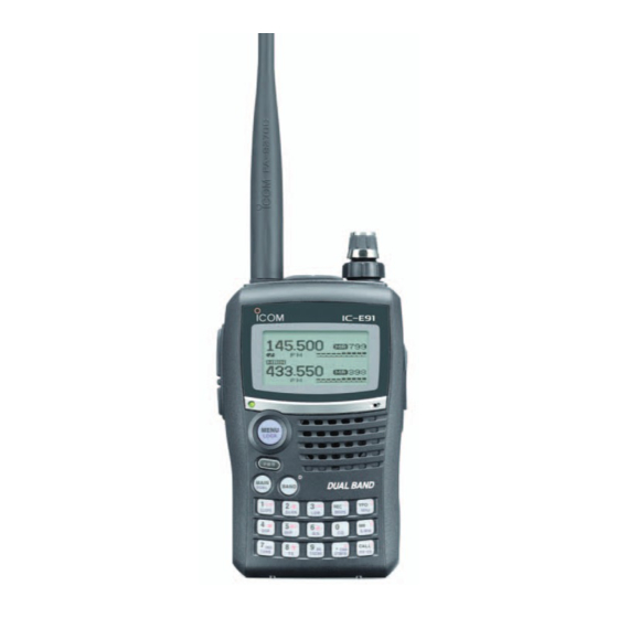
- Page 1 INSTRUCTION MANUAL VHF/UHF FM TRANSCEIVER iE91...
-
Page 2: Explicit Definitions
With proper care, this product should provide you with years of trouble-free operation. We want to take a couple of mo- IMPORTANT ments of your time to thank you for making your IC-E91 your radio of choice, and hope you agree with Icom’s philosophy of “technology first.”... -
Page 3: Precautions
PRECAUTIONS RWARNING RF EXPOSURE! NEVER expose the transceiver to rain, snow or any liquids. This device emits The transceiver may be damaged. Radio Frequency (RF) energy. Caution should be observed when operating this device. If you have any questions re- NEVER operate or touch the transceiver with wet hands. -
Page 4: Table Of Contents
TABLE OF CONTENTS FOREWORD …………………………………………………………… i BASIC OPERATION ……………………………………… 20–28 I Receiving ……………………………………………………… 20 EXPLICIT DEFINITIONS ……………………………………………… i I Setting audio volume ………………………………………… 20 FEATURES ……………………………………………………………… i I Setting squelch level ………………………………………… 21 IMPORTANT …………………………………………………………… i I Operating mode selection …………………………………… 21 PRECAUTIONS ………………………………………………………... - Page 5 I EMR communication ………………………………………… 56 11 MENU SCREEN OPERATION ………………………… 85–102 I Low-speed data communication …………………………… 56 I General ………………………………………………………… 85 I GPS operation ………………………………………………… 58 I MENU screen indication for B band ………………………… 86 I Other functions for DV mode operation …………………… 62 I Menu list ………………………………………………………...
-
Page 6: Supplied Accessories
I Time-out timer ……………………………………………… 115 SUPPLIED ACCESSORIES I PTT lock ……………………………………………………… 115 I [MIC/SP] jacks ……………………………………………… 115 I Cloning function …………………………………………… 116 The following accessories are supplied with the transceiver. I Resetting …………………………………………………… 117 q Hand strap ………………………………………………… 1 w Antenna …………………………………………………… 1 13 TROUBLESHOOTING …………………………………………... -
Page 7: Accessory Attachment
ACCESSORY ATTACHMENT I Antenna I Handstrap Insert the supplied antenna into the Slide the handstrap through the loop antenna connector and screw down on the top of the belt clip as illustrated Jack cover the antenna as shown at left. at left to facilitate carrying the transceiver. -
Page 8: Panel Description
PANEL DESCRIPTION I Front, top and side panels w TX/RX INDICATOR [TX/RX] (p. 24) Lights green while receiving a signal or when the squelch is open; lights red while transmitting. e PTT SWITCH [PTT] (p. 24) Push and hold to transmit, release to receive. r SQUELCH KEY [SQL] ➥... - Page 9 PANEL DESCRIPTION o CALL/RX➝CS KEY [CALL]/[RX➝CS](CALL) !3 EXTERNAL DC IN JACK [DC IN] ➥ Push to select the call channel/TV channel. (p. 16) ➥ Connects the supplied wall charger, BC-167A/D, to ➥ During DV mode operation, push and hold for 1 sec. to charge the attached battery pack.
- Page 10 PANEL DESCRIPTION D D KEYPAD Pushed momentarily Pushed and held for 1 sec. • Inputs digit ‘1’ for frequency input, memory channel selection, • Displays the simple band scope for a single sweep. (p. 23) etc. • While pushing [PTT], this key sends the DTMF code “1.” •...
- Page 11 PANEL DESCRIPTION Pushed momentarily Pushed and held for 1 sec. • Inputs digit ‘7’ for frequency input, memory channel selection, • During FM/FM-N mode operation, selects repeater tone, tone etc. squelch, DTCS squelch and no tone operation in sequence. • While pushing [PTT], this key sends the DTMF code “7.” (p.
-
Page 12: I Function Display
PANEL DESCRIPTION I Function display q BATTERY INDICATOR (pgs. 10, 12) • Single band indication ➥ “ ” (battery indicators) appear when the Li-ion bat- tery pack is attached. ➥ “ -DUP DSQL ” appears when the battery pack must be charged. PRIO ➥... - Page 13 PANEL DESCRIPTION ➥ “S” appears with the “DSQL” or “CSQL” indicator !1 S/RF METER ➥ Shows the relative signal strength while receiving sig- while the pocket beep function (with digital call sign or dig- is in use. (p. 111) nals. ital code squelch) ➥...
-
Page 14: Battery Charging
• R DANGER! NEVER incinerate an used battery pack since internal battery gas may cause it to rupture, or may cause • R DANGER! Use and charge only specified Icom battery an explosion. packs with Icom radios. Only Icom battery packs are tested •... - Page 15 The charger is not waterproof. • CAUTION! DO NOT charge the battery outside of the spec- ified temperature range: 0˚C to +35˚C. Icom recommends charging the battery at +20˚C. The battery may heat up or rupture if charged out of the specified temperature range.
-
Page 16: I Regular Charging
BATTERY CHARGING I Regular charging Prior to using the transceiver for the first time, the battery • BC-167A/D pack must be fully charged for optimum life and operation. Transceiver D D Battery indicators to AC outlet The indicators show “ ,”... -
Page 17: I Rapid Charging
BATTERY CHARGING I Rapid charging The optional BC-139 provides rapid charging of the battery Transceiver pack. (with battery pack) Battery pack • Charging period: 2.5 hours (with BP-217) Turn power OFF. to AC outlet D D Charging note Check the •... -
Page 18: I Optional Battery Case
BATTERY CHARGING I Optional battery case I Battery information ➥ Install 2 R6 (AA) size alka- D D Battery life line batteries into the op- The transceiver operates with the BP-217 as follows. tional BP-216 BATTERY However, when operating in DV mode, operating time may be CASE shortened by one-half hour. -
Page 19: I External Dc Power Operation
BATTERY CHARGING I External DC power operation An optional cigarette lighter cable CP-19R; for 12 V cigarette Transceiver or external DC power cable can be lighter socket) (OPC-254L) used for external power operation. • CP-19R (Optional) to cigarette lighter socket (12 V DC) D D Operating note •... -
Page 20: Frequency And Channel Setting
FREQUENCY AND CHANNEL SETTING I Main band selection The IC-E91 has two independent operating bands; A band D D How to change the main band and B band . A band can operate (VFO A) (VFO B) (VFO A) ➥ Push [MAIN/DUAL] to toggle between A and B band. -
Page 21: I Mode Selection
FREQUENCY AND CHANNEL SETTING I Mode selection D D VFO mode D D Memory mode VFO mode is used to set the desired frequency. Memory mode is used for operation on memory channels which store programmed frequencies. ➥ Push [VFO] to select VFO mode. q Push [MR] to select memory mode. -
Page 22: I Operating Band Selection
FREQUENCY AND CHANNEL SETTING I Operating band selection D D Call/TV* channels Call channels are used for quick recall of most-often used fre- The transceiver can receive the AM broadcast, HF bands, quencies. 50 MHz, FM broadcast, VHF air, 144 MHz, 300 MHz, *Appears only when TV channels are programmed via the 400 MHz or 800 MHz* bands. - Page 23 FREQUENCY AND CHANNEL SETTING • Available frequency bands • A band +DUP +DUP DTCS DTCS +DUP +DUP DTCS DTCS +DUP +DUP DTCS DTCS +DUP +DUP DTCS DTCS PRIO PRIO WX WX EMR PRIO PRIO WX WX EMR PRIO PRIO WX WX EMR PRIO PRIO WX...
-
Page 24: I Setting A Tuning Step
I Setting a frequency The tuning step can be selected for each frequency band. D D Using the dial The following tuning steps are available for the IC-E91. q Push [VFO] to select VFO mode, if necessary. † • 5.0 kHz* •... - Page 25 FREQUENCY AND CHANNEL SETTING D D Using the keypad • Entering 145.520 MHz • Entering 79.3 MHz • Changing 100 kHz The frequency can be directly set via numeric and below. keys. +DUP DTCS +DUP DTCS • If a frequency outside the frequency range is en- Editting PRIO WX PRIO WX...
-
Page 26: Basic Operation
BASIC OPERATION I Receiving I Setting audio volume ➥ Rotate [VOL] to adjust the audio level. Make sure charged battery pack (BP-217) or brand new al- kaline batteries (BP-216) are installed (pgs. 1, 12). • If squelch is closed, push and hold [SQL] to verify the audio level. -
Page 27: I Setting Squelch Level
BASIC OPERATION I Setting squelch level I Operating mode selection The squelch circuit mutes the received audio signal depend- Operating modes are determined by the modulation of the ing on the signal strength. The receiver has 9 squelch levels, radio signals. The transceiver has total 5 operating modes (A a continuously open setting and an automatic squelch setting. -
Page 28: I Monitor Function
BASIC OPERATION I Monitor function I Attenuator function This function is used to listen to weak signals without disturb- The attenuator prevents a desired signal from distortion by ing the squelch setting or to open the squelch manually even very strong signals near the desired frequency or when very when mute functions such as the tone squelch are in use. -
Page 29: I Band Scope
BASIC OPERATION I Band scope D D Continuous sweep The band scope function allows you to visually check a spec- ified frequency range around the center frequency. q Set the desired frequency as band scope center frequency. w Push and hold [SCOPE](1) for 3 sec. to start continuous About the sweep steps: The specified tuning step in each sweep. -
Page 30: I Transmitting
BASIC OPERATION I Transmitting I Transmit power selection The transceiver has two output power levels to suit your op- CAUTION: Transmitting without an antenna will damage erating requirements. Low output power during short-range the transceiver. communications may reduce the possibility of interference to other stations and will reduce current consumption. -
Page 31: I Lock Function
To prevent accidental frequency changes and unnecessary Dualwatch operation monitors two frequencies simultane- function access, use the lock function. ously. The IC-E91 has two independent receiver circuits as A band and B band (available frequency bands and operating mode ➥ Push and hold [MENU/LOCK] for 1 sec. to turn the lock are different depending on bands) function ON and OFF. - Page 32 BASIC OPERATION D D Main band selection D D Setting audio volume ➥ Push [MAIN/DUAL] to select A band or B band as the The audio level for dualwatch operation can be adjusted both main operating band alternately. on A band and B band simultaneously (default). This setting can be set separately for each band in sounds +DUP DTCS...
- Page 33 BASIC OPERATION D D Volume setting for dualwatch D D Setting squelch level qPush and hold [MAIN/DUAL] for 1 sec. to enter the dual- The volume setting for dualwatch can be set for both bands simultaneously or for each band separately in set mode. watch operation, if necessary wWhile pushing and holding [SQL], rotate [DIAL] to adjust q Enter “VOLUME SELECT”...
-
Page 34: I Tv Channel Operation
BASIC OPERATION I TV channel operation w Rotate [DIAL] to select the channel to be skipped. TV channel operation is available only when TV channels are programmed using the optional RS-91. Also available (p. 121) • To clear the skip setting, rotate [DIAL] while pushing and holding for A band operation only. -
Page 35: Repeater And Duplex Operations
REPEATER AND DUPLEX OPERATIONS I General • Repeater operation flow chart Repeaters allow you to extend the operational range of your radio because a repeater has much higher output power than Step 1: the typical transceiver. Set the desired band to operate the repeater. Normally, a repeater has independent frequencies for each receiver and transmitter. -
Page 36: I Accessing A Repeater
REPEATER AND DUPLEX OPERATIONS I Accessing a repeater q Set the receive frequency r Push and hold [PTT] to transmit. (repeater output frequency) w Set the shift direction of the transmit frequency. • The displayed frequency automatically changes to the transmit (–DUP or frequency (repeater input frequency). -
Page 37: D Checking The Repeater Input Signal
REPEATER AND DUPLEX OPERATIONS D Checking the repeater input signal D D Off band indication The transceiver can check whether the other station’s trans- If the transmit frequency is out of the amateur band, the off mit signal can be received directly or not, by listening on the band indication, “OFF,”... -
Page 38: I Duplex Operation
REPEATER AND DUPLEX OPERATIONS I Duplex operation D Setting duplex direction Although [DIAL] and [ï](5) are used for description in this ➥ Push and hold [DUP](4) for 1 sec. to select “–DUP” or section, [∫ ∫ ](2)/[√ √ ](8) and [≈ ≈ ](6) are available instead of [DIAL] and [ï](5). -
Page 39: I 1750 Hz Tone
REPEATER AND DUPLEX OPERATIONS I 1750 Hz tone i Push and hold [PTT] to transmit. Some European repeaters require a 1750 Hz tone burst to be o Release [PTT] to receive. accessed. For such European repeaters, perform the follow- !0 Push and hold [SQL] to check whether the other station’s ing. -
Page 40: Dv Mode Operation (Optional Ut-121 Is Required)
Enter “MY” in call sign set mode. ➪ ➪ MENU screen CALL SIGN MY When the optional UT-121 is installed, the IC-E91 can be op- † † (Push [MENU/LOCK]) (Rotate [DIAL] , then push [ï](5) erated in digital voice mode and low-speed data operation for •... - Page 41 DV MODE OPERATION (Optional UT-121 is required) y Push [≈ ≈ ](6) to select 2nd digit, then rotate [DIAL] !0 Push [ï](5) to store the programmed call sign with note † to se- lect the desired character or code. and returns to MY CALL SIGN screen. !1 Push [MENU/LOCK] to return to frequency indication.
- Page 42 DV MODE OPERATION (Optional UT-121 is required) D D Station call sign programming y Push [≈ ≈ ](6) to select 2nd digit, then rotate [DIAL] † to se- Station call sign must be programmed for the specified sta- lect the desired character or code. tion call as well as repeater operation in both digital voice and •...
- Page 43 ✔ For your information The IC-E91 has call sign edit record function. When editing a call sign stored in a call sign memory, regular memory or call channel, the default setting is to store the edited call sign into a blank channel automatically.
-
Page 44: I Digital Voice Mode Operation
DV MODE OPERATION (Optional UT-121 is required) I Digital voice mode operation qSet the desired frequency in B band. NOTE: The digital mode operation is vastly different from (pgs. 14, 18) • Select output power, if desired. (p. 24) FM mode. One of the differences is in digital mode the w Select DV mode. - Page 45 DV MODE OPERATION (Optional UT-121 is required) D D When calling the desired station D D When sending a CQ Continued instruction from step x on page 38. Continued instruction from step x on page 38. cRotate [DIAL] † † cRotate [DIAL] †...
-
Page 46: I About D-Star System
Repeater D Repeater C About time-out timer function 144/430 MHz The IC-E91 has a time-out timer function for digital re- 144/430 MHz peater operation. The timer limits a continuous transmis- sion for approx. 10 min. Warning beeps will sound before... -
Page 47: I Digital Repeater Operation
DV MODE OPERATION (Optional UT-121 is required) I Digital repeater operation u Repeat the steps t and y to enter the desired repeater Repeater call signs must be programmed for repeater opera- tion in both digital voice and low-speed data communications. call sign. - Page 48 DV MODE OPERATION (Optional UT-121 is required) D D Repeater operation in the same zone t Push [PTT] to transmit; release to receive. qSet the desired repeater’s frequency, offset and shift direc- tion in B band. (pgs. 18, 32) • Select DV mode in advance. (p. 21) w Set your own call sign.
- Page 49 DV MODE OPERATION (Optional UT-121 is required) • Setting example 1 Zone Area 1 Repeater 1 Area 2 Repeater 2 Area 3 Repeater 3 Area 4 Repeater 4 : A11111 : A22222 (Gateway) : A33333 : A44444 Station A Station C Station B : A2222A : A4444C...
- Page 50 DV MODE OPERATION (Optional UT-121 is required) D D Repeater operation into another zone nPush [ï](5) to set the call sign for “R2.” qSet the desired repeater’s frequency, offset and shift direc- • Return to CALL SIGN screen. tion in B band. (pgs.
- Page 51 DV MODE OPERATION (Optional UT-121 is required) • Setting example 2 Zone A Repeater 3 Repeater 3 3 Repeater 3 Area 1 Area 2 Area 4 : A33333 : A33333 : A33333 Area 3 (Gateway) Repeater 1 Repeater 2 Repeater 4 : A11111 : A22222 : A44444...
-
Page 52: I Received Call Sign
DV MODE OPERATION (Optional UT-121 is required) I Received call sign • Station call sign • Called station call sign RX CALL SIGN RX CALL SIGN When a call is received in DV mode, the calling station and RX01 RX01 RX01 RX01 CALLER:... - Page 53 DV MODE OPERATION (Optional UT-121 is required) D D One-touch reply using the call record The stored call signs in the call record can be used to the call. Important! Setting call signs with the “One-touch reply using the call qAfter receiving a call, push and hold [RX➝CS](CALL) for record”...
-
Page 54: I Copying The Call Sign
DV MODE OPERATION (Optional UT-121 is required) I Copying the call sign • When “AUTO” is set to “EDIT RECORD” item D D Copying the call sign memory contents r Push [≈ ≈ ](6) to select the call sign programming mode. This function is convenient when or modifying a part of the •... - Page 55 DV MODE OPERATION (Optional UT-121 is required) • When “SELECT” is set to “EDIT RECORD” item r Push [≈ ≈ ](6) to select the call sign programming mode. • The 1st digit of the selected call sign blinks. tEdit or modify the selected call sign as described in “D Sta- tion call sign programming”...
-
Page 56: D Copying The Call Record Contents Into Call Sign Memory
DV MODE OPERATION (Optional UT-121 is required) D D Copying the call record contents into call sign memory This is a way to copying the call record contents • When “CALLER,” “RXRPT1” or “RXRPT2” is (“CALLER,” into call sign memory “RXRPT1”... -
Page 57: I Break-In Communication
DV MODE OPERATION (Optional UT-121 is required) I Break-in communication • How to use the break-in? While operating with the call sign squelch , the (p. 110) The break-in function allows you to break into a conversation, squelch never opens even if a call is re- (no audio sounds) where the two original stations are communicating with call... -
Page 58: I Message Operation
DV MODE OPERATION (Optional UT-121 is required) I Message operation D D TX message programming r Rotate [DIAL] † TX messages are available for up to 5 channels and each to select the desired character or symbol. • Push [A/a](3) to change the character group from “AB” (alpha- channel can be programmed with a message of up to 20 betical characters;... - Page 59 B band. wPerform the steps q to e in “D TX message program- NOTE: Only 1 message can be stored in the IC-E91. The ming” as at left. received message is cleared by turning power OFF, or eRotate [DIAL] †...
-
Page 60: I Automatic Reply Function
DV MODE OPERATION (Optional UT-121 is required) I Automatic reply function D D RX message indication The automatic reply function replies to calls by a station that specified your call sign. The received message can also be checked in DV set mode. Two methods of replying are available—... - Page 61 DV MODE OPERATION (Optional UT-121 is required) D D Voice memory recording for automatic reply D D Play-back or erase the voice memory q Push [MENU/LOCK] to select menu mode indication. IMPORTANT! wRotate [DIAL] † to select “DV VOICE MEMO,” then push Deactivate the dualwatch function and set minimum [VOL] †...
-
Page 62: I Emr Communication
DV MODE OPERATION (Optional UT-121 is required) I EMR communication I Low-speed data communication The EMR communication mode is available for digital mode In addition to the digital voice communication, low-speed data operation. In the EMR communication mode, no call sign set- communication is available. - Page 63 , then push [ï](5) w Rotate [DIAL] † to select “PTT” or “AUTO.” • Port : The same COM port number as IC-E91’s ePush [ï](5) to return to DV set mode, and push • Baud rate : 38.4 kbps (or [Ω Ω ](4)) (fixed value)
-
Page 64: I Gps Operation
During GPS mode operation, a GPS receiver (RS-232C out- can be connected to the [DATA] socket of put/NMEA format) q Enter “GPS MODE” in DV set mode. (p. 94) the IC-E91 to indicate the current position (Latitude and Longi- ➪ ➪ MENU screen DV SET MODE... -
Page 65: D Gps Message Programming
DV MODE OPERATION (Optional UT-121 is required) D D GPS message programming t Repeat the steps r and t to enter the desired message. q Enter “GPS” in message/position set mode. • Up to 20-character messages can be set. ➪ ➪... - Page 66 DV MODE OPERATION (Optional UT-121 is required) D D GPS message automatic transmission D D Position indication q Enter “GPS AUTO TX” in DV set mode. q Enter “POSITION” in message/position set mode. (p. 95) ➪ ➪ ➪ ➪ MENU screen DV SET MODE...
- Page 67 DV MODE OPERATION (Optional UT-121 is required) D D Received GPS message indication q Enter “RX GPS” in message/position set mode. ➪ ➪ MENU screen MESSAGE/POSITION RX GPS † † (Push [MENU/LOCK]) (Rotate [DIAL] , then push [ï](5) • RX GPS MESSAGE screen is displayed. RX GPS MESSAGE RX GPS MESSAGE DATA:...
-
Page 68: I Other Functions For Dv Mode Operation
I Other functions for DV mode operation D D DV voice memory N Track size setting The IC-E91 has a DV voice memory that records a total 30 The track size can be changed with the following instruction. second of received audio. - Page 69 DV mode in B band, and deactivate the priority ceived during DV mode operation. watch if activated. (p. 83) The IC-E91 DV automatic detection monitors in FM mode w Enter “TRACK” in DV voice memo set mode. when other than DV mode signal is received. ➪ ➪...
-
Page 70: Memory/Call Channels
I Selecting a memory channel D D Using [DIAL]— Programmed channels The IC-E91 has 850 memory channels in A band, 450 mem- ory channels in B band, and 2 call channels in each band. qPush [MR] to select memory mode. -
Page 71: I Selecting A Call Channel
MEMORY/CALL CHANNELS I Selecting a call channel qPush [CALL] to select call channel mode. [DIAL] Blinks • Pushing [CALL] toggles call, TV* channels. 145 000 µ wRotate [DIAL] to select the desired call channel. BANK :---- • “C0” and “C1” are selectable. MNAME: *Appears only when TV channels are programmed via the SKIP :OFF... -
Page 72: I Memory Channel Programming
MEMORY/CALL CHANNELS I Memory channel programming q Push [VFO] to select VFO mode. [EXAMPLE]: Programming 145.870 MHz into memory chan- w Set the desired frequency: nel 11 (blank channel). ➥ Select the desired band with [BAND]. Push and hold ➥ Set the desired frequency with [DIAL]. ➥... -
Page 73: I Memory Bank Setting
I Memory bank setting rPush [Ω Ω ](4) or [≈ ≈ ](6) several times to select the desired The IC-E91 has a total of 26 banks (A to Z). Regular memory channels, 000 to 799 (A band)/000 to 399 (B band), are as- bank group from “A”... -
Page 74: I Memory Bank Selection
MEMORY/CALL CHANNELS I Memory bank selection qPush [MR] several times to select memory bank mode. eRotate [DIAL] to select the bank channel. wWhile pushing and holding [BAND], rotate [DIAL] to select • Only programmed channels are displayed. the desired bank (A to Z). [DIAL] •... -
Page 75: I Programming Memory/Bank/Scan Name
MEMORY/CALL CHANNELS I Programming memory/bank/scan name Each memory channel can be programmed with an alphanu- • Push [≈ ≈ ](6) to move the cursor right; push [Ω Ω ](4) to move the meric channel name for easy recognition and can be indi- cursor left. -
Page 76: I Selecting Memory/Bank Name Indication
MEMORY/CALL CHANNELS I Selecting memory/bank name [EXAMPLE]: Programming the bank name “AIR” into the scan edge channel 03A. indication Push Push to select memory mode. to select BNAME *. During memory mode operation, either the programmed memory name or bank name can be displayed below the fre- 127 500 145 870 µ... -
Page 77: I Copying Memory/Call Contents
MEMORY/CALL CHANNELS I Copying memory/call contents Holding [S.MW](MR) for 2 sec. at the step w, will also This function transfers a memory channel’s contents to VFO (or another memory/call channel). This is useful when search- copy the memory contents to VFO. In this case, the steps e and r are not necessary. -
Page 78: I Memory Clearing
MEMORY/CALL CHANNELS I Memory clearing Contents of programmed memories can be cleared (blanked), VFO mode Push if desired. 145 870 to select CLEAR . qPush and hold [S.MW](MR) for 1 sec. to enter select mem- 145 000 PSKIP PSKIP µ ory write mode. -
Page 79: I Erasing/Transferring Bank Contents
MEMORY/CALL CHANNELS I Erasing/transferring bank contents The bank contents of programmed memory channels can be ePush [∫ ∫ ](2) or [√ √ ](8) to select “BANK.” rPush [≈ ≈ ](6) or [Ω Ω ](4) several times to select the desired cleared or reassigned to another memory bank. -
Page 80: Scan Operation
SCAN OPERATION I Scan types Scanning searches for signals automatically and makes it There are 7 scan types and 4 resume conditions to suit your easier to locate new stations for contact or listening purposes. operating needs. Repeatedly scans all frequen- Repeatedly scans all frequen- FULL SCAN SELECTED BAND SCAN... -
Page 81: I Full/Band/Programmed Scan
SCAN OPERATION I Full/band/programmed scan q Push [VFO] r To start the scan, release [SCAN](2). to select VFO mode • Select the desired frequency band with [BAND], if desired. • Scan pauses when a signal is received. w Set the squelch level. •... -
Page 82: I Scan Edges Programming
SCAN OPERATION I Scan edges programming t Push and hold [S.MW](MR) for 1 sec. Scan edges can be programmed in the same manner as memory channels. Scan edges are programmed into scan • 3 beeps sound • The other scan edge channel “B,” 00B to 24B, is automatically edges, 00A/00B to 24A/24B, in memory channels. -
Page 83: I Memory Scan
SCAN OPERATION I Memory scan r Release [SCAN](2) to start the selected scan. IMPORTANT!: To perform memory scan, 2 or more mem- ory channels MUST be programmed, otherwise the scan • Scan pauses when a signal is received. • Rotate [DIAL] to change the scanning direction, or resumes will not start. -
Page 84: I Memory Bank Scan
SCAN OPERATION I Memory bank scan r Release [SCAN](2) to start the selected scan. IMPORTANT!: To perform memory bank scan, 2 or more bank channels MUST be programmed, otherwise the scan • Scan pauses when a signal is received. • Rotate [DIAL] to change the scanning direction, or resumes will not start. -
Page 85: I Skip Channel/Frequency Setting
SCAN OPERATION I Skip channel/frequency setting Memory channels can be set to be skipped for memory skip ePush [∫ ∫ ](2) or [√ √ ](8) several times to select “SKIP.” scan. In addition, memory channels can be set to be skipped for both memory skip scan and frequency skip scan. - Page 86 SCAN OPERATION tPush and hold [S.MW](MR) for 1 sec. to store the skip con- ✔ CONVENIENT! dition into the memory. During VFO scanning, such as programmed scan, the skip • “SKIP” or “P SKIP” indicator appears, according to the skip se- setting can be programmed into the highest blank memory lection in the step r.
-
Page 87: I Scan Resume Condition
SCAN OPERATION I Scan resume condition D D Scan pause timer D D Scan resume timer The scan pauses when receiving signals according to the The scan restarts after the signal disappears according to the scan pause time. It can be set from 2 to 20 sec. or unlimited. resume time. -
Page 88: Priority Watch
PRIORITY WATCH I Priority watch types Priority watch checks for signals on the frequency every MEMORY/CALL CHANNEL WATCH 5 sec. while operating on a VFO frequency or scanning. The While operating on a VFO fre- 5 sec. transceiver has 3 priority watch types to suit your needs. quency, priority watch checks for Memory a signal on the selected every 5... -
Page 89: I Priority Watch Operation
PRIORITY WATCH I Priority watch operation Although [DIAL] and [ï](5) are used for description in this • During priority watch section, [∫ ∫ ](2)/[√ √ ](8) and [≈ ≈ ](6) are available instead of PRIO PRIO PRIO PRIO [DIAL] and [ï](5). 433 260 145 180 D D Memory/call channel and memory scan watch... -
Page 90: Priority Watch
PRIORITY WATCH D D VFO scan watch i Push [VFO] to cancel the watch. q Set the watching channel(s). For memory channel watch: • During priority watch Select the desired memory channel. PRIO PRIO PRIO PRIO For call channel watch: 888 800 145 000 Select the desired call channel. -
Page 91: Menu Screen Operation
MENU SCREEN OPERATION I General rRotate [DIAL] † MENU screen is used for programming infrequently changed to select the desired value or condition, values or conditions of functions. then push [ï](5) to return to the setting item selection mode. D D Entering MENU screen and operation AUTO POWER OFF e.g.) Set “AUTO power OFF”... -
Page 92: I Menu Screen Indication For B Band
MENU SCREEN OPERATION I MENU screen indication for I Items list B band* D D Set mode While B band is selected, MENU screen shows following in- ITEMS REF. ITEMS REF. dication. p. 88 p. 89 AUTO POWER OFF AUTO POWER ON ***** MENU ***** ***** MENU ***** p. - Page 93 MENU SCREEN OPERATION D D DV set mode D D DUP/TONE set mode Not available for the TV band selection. Available for B band when the UT-121 is installed. ITEMS REF. ITEMS REF. ITEMS REF. ITEMS REF. p. 97 p. 98 OFFSET FREQ DTCS CODE p.
-
Page 94: I Set Mode Items
MENU SCREEN OPERATION I Set mode items D D Auto power OFF D D Power save The transceiver can be set to automatically turn OFF after a The power save function reduces the current drain to con- specified time period with a beep when no key operations are serve battery power. - Page 95 MENU SCREEN OPERATION D D Monitor key action D D Microphone simple mode The monitor key, [SQL] , can be set as a ‘sticky’ key. When Microphone simple mode is used to change the function as- set to the sticky condition, each push of [SQL] toggles the signments for keys on the optional HM-75A REMOTE CONTROL monitor function ON and OFF.
- Page 96 MENU SCREEN OPERATION D D Key lock Type D D Busy lockout While the key lock function is ON, [PWR], [PTT], [SQL], Turns the busy lockout function ON and OFF. [VOL] and [MENU]( can still be accessed. This function inhibits transmission while receiving a signal or Lock function only) Accessible keys can be set to 1 of 4 groups.
- Page 97 MENU SCREEN OPERATION D D Active band Allows continuous frequency selection of the operating fre- quency across all bands. • SINGLE : A single operating frequency can be se- lected within the current band. Push [BAND] for band selection in this case. •...
-
Page 98: I Dv Set Mode Items
MENU SCREEN OPERATION I DV set mode items D D Digital code The following items are selectable when the optional UT-121 is installed. Sets the desired digital code for digital code squelch opera- tion. Total of 100 codes (00–99) are available. (default: 00) D D Auto reply DIGITAL CODE... - Page 99 MENU SCREEN OPERATION D D Digital monitor D D RX call sign auto write Sets the desired monitoring mode during digital mode opera- When an individual station call is received, the calling station tion from “Auto,” “Digital” and “Analog.” call sign can be automatically set in “UR.” (default: OFF) •...
- Page 100 MENU SCREEN OPERATION D D GPS mode • Sentence formatter setting Sets GPS mode operation ON and OFF. q Select “ON” in GPS mode item, then push [ï](5) † to enter When the position information is received from a connected the sentence formatter selection.
- Page 101 MENU SCREEN OPERATION D D GPS auto TX timer D D Call sign edit record Selects the desired interval for automatic position transmis- Selects the call sign programming when the call sign is edited sion function from 5, 10, 30 second, 1, 3, 5, 10, 30 minutes or corrected with the pre-programmed call sign.
-
Page 102: I Scan Set Mode Items
MENU SCREEN OPERATION I Scan set mode items D D Priority watch D D Scan resume timer Activates priority watch or priority watch with alert Selects the scan resume time from a paused frequency after (Bell) • OFF : The priority watch is turned OFF. the received signal disappears. -
Page 103: I Dup/Tone Set Mode Items
MENU SCREEN OPERATION I DUP/TONE set mode items D D Memory bank link function D D Offset frequency Sets the memory bank link function ON and OFF. The (default) Sets the offset frequency for duplex operation within (repeater) link function provides continuous bank scan, scanning all con- 0 to 159.995 MHz range. - Page 104 MENU SCREEN OPERATION D D TSQL frequency D D DTCS code Selects tone frequency for tone squelch or pocket beep oper- Selects DTCS code for DTCS squelch (both encoder/decoder) ation from one of 50 available frequencies operation. Total of 104 codes (023–754) are available. (67.0–254.1 Hz) (default: 88.5) (default: 023)
-
Page 105: I Display Set Mode Items
MENU SCREEN OPERATION I Display set mode items D D DTCS polarity Sets DTCS polarity from “BOTH N” , “TN-RR” (TX/RX: normal) D D Display backlighting , “TR-RN” (TX: normal, RX: reverse) (TX: reverse, RX: normal) The transceiver has display backlighting with a 5 sec. timer “BOTH R”... - Page 106 MENU SCREEN OPERATION D D LCD contrast D D TX Call Sign Display Available when the UT-121 is installed. The contrast of the LCD can be selected from 16 levels. Selects call sign display function from YOUR, MY and OFF. •...
- Page 107 (Max. 5 items are displayed at the same time) (default) The opening logo indication (Icom logo and transceiver name) • SMALL : Makes 6 lines that is displayed at power ON can be skipped, if desired. (Max. 6 items are displayed at the same time) •...
-
Page 108: I Sounds Set Mode Items
MENU SCREEN OPERATION I Sounds set mode items D D Scope audio output Select the audio output function capability during sweep with D D Beep output level band scope function. • ON : The received audio sounds during sweep. (default) Adjusts the key-touch beep tone level to the desired level •... -
Page 109: Other Functions
OTHER FUNCTIONS DTMF MEMORY Ch01 I Programming a DTMF code r Push the desired keys to input the characters. DTMF codes are used for autopatching, accessing repeaters, controlling other equipment, etc. The transceiver has 10 • [0]–[9] input “0”–“9,” [A](VFO) inputs “A,” [B](MR) inputs “B,” [C](CALL) inputs “C,”... -
Page 110: I Transmitting A Dtmf Code
OTHER FUNCTIONS +DUP DTCS PRIO WX EMR 438 500 I Transmitting a DTMF code MemoName PSKIP µ D Transmitting from DTMF memory D Transmitting a DTMF code directly 5D28AB4 The selected DTMF code is transmitted at each push of the DTMF code can be transmitted via keypad directly while [SQL] switch while transmitting. -
Page 111: I Clearing A Dtmf Memory
SQL:BACK MAIN:CLR OTHER FUNCTIONS DTMF MEMORY Ch01 I Clearing a DTMF memory I Confirming a DTMF memory SQL:BACK MAIN:CLR An unwanted DTMF memory can be cleared (erased). A DTMF memory can be confirmed with a DTMF tone. q Push and hold [DTMF.M](.) for 1 sec. to enter DTMF mem- q Push and hold [DTMF.M](.) for 1 sec. -
Page 112: I Setting Dtmf Transfer Speed
OTHER FUNCTIONS I Setting DTMF transfer speed I Tone frequency and DTCS code The DTMF transfer speed can be selected. D Subaudible (repeater) tone q Enter “DTMF SPEED” in DUP/TONE… set mode. (p. 99) ➪ ➪ MENU screen DUP/TONE... DTMF SPEED Some repeaters require subaudible tones to be accessed. -
Page 113: Tone Squelch
***** MENU ***** OTHER FUNCTIONS DV SET MODE SCAN DUP/TONE... D Setting subaudible tones for repeater or D Setting DTCS code for DTCS squelch or CTCSS TONE REPEATER TONE tone squelch beep 88.5 88.5 q Enter “CTCSS TONE (or RPT TONE)” in DUP/TONE… set q Enter “DTCS CODE”... -
Page 114: I Digital Code And Digital Call Sign Setting
OTHER FUNCTIONS ***** MENU ***** DV VOICE M SET MODE I Digital code and digital call sign setting DV SET MODE The optional UT-121 is required D Setting digital code for digital code squelch D Setting the YOUR and MY call signs for DIGITAL CODE or beep digital call sign squelch or beep... - Page 115 OTHER FUNCTIONS ***** MENU ***** CALL SIGN RX CALL S MESSAGE/POS YOUR CALL SIGN ABCDEF y Rotate [DIAL] † to select the desired call sign. CAUTION!: Use digital code squelch when operating with • Input the call sign if the desired call sign is not stored in the more than 3 stations.
-
Page 116: I Tone/Dtcs Squelch
OTHER FUNCTIONS I Tone/DTCS squelch I Digital code/digital call sign squelch q Set the desired operating frequency, CTCSS tone and The optional UT-121 is required DTCS code. q Set the desired operating frequency on DV mode, Digital w Push and hold [TONE](7) for 1 sec. several times to acti- vate the tone or DTCS squelch. -
Page 117: I Pocket Beep Function
+DUP TSQL +DUP DTCS PRIO WX EMR PRIO WX EMR 145300 145300 MemoName MemoName PSKIP PSKIP OTHER FUNCTIONS I Pocket beep function I DTCS polarity setting +DUP DSQL +DUP CSQL PRIO WX EMR PRIO WX EMR 145300 145300 MemoName q Set the desired operating frequency. MemoName q Enter “DTCS P”... -
Page 118: I Tone Scan
OTHER FUNCTIONS I Tone scan The transceiver can detect the subaudible tone frequency and [DIAL] DTCS code in a received signal. By monitoring a signal that is being transmitted on a repeater input frequency, you can determine the tone frequency required to access the repeater. q Set the desired frequency or memory channel to be checked for a tone frequency or DTCS code. -
Page 119: I Beep Tones
OTHER FUNCTIONS I Beep tones I Key lock effect You can select to have confirmation beeps sound at the push D Lock function of a switch. The output level can be adjusted within 39 levels The lock function prevents accidental frequency changes and or to the related level of the volume with “BEEP LEVEL”... -
Page 120: I Power Save
OTHER FUNCTIONS I Power save I Auto power OFF The power save function reduces the current drain to con- The transceiver can be set to automatically turn OFF after a serve battery power. specified period with a beep when no switch is pushed. 120 min., 90 min., 60 min., 30 min. -
Page 121: I Time-Out Timer
OTHER FUNCTIONS I Time-out timer I [MIC/SP] jacks To prevent accidental prolonged transmission, etc., the trans- To connect external equipment such as speaker, microphone, ceiver has a time-out timer. This timer cuts a transmission TNC, etc. refer to the diagram below. OFF after 1, 3, 5 or 10 min. -
Page 122: I Cloning Function
OTHER FUNCTIONS I Cloning function The IC-E91 has transceiver-to-transceiver data cloning capa- The optional RS-91 is also REMOTE CONTROL SOFTWARE ® bility. This function is useful when you want to copy all of the available to clone/edit contents with a PC (for Microsoft Win- ®... -
Page 123: I Resetting
OTHER FUNCTIONS I Resetting D All reset D Partial reset The function display may occasionally display erroneous information (e.g. q Push and hold [PWR] for 1 sec. to q Push and hold [PWR] for 1 sec. to when first applying power). This may be turn power OFF. -
Page 124: Troubleshooting
TROUBLESHOOTING If your transceiver seems to be malfunctioning, please check the following points before sending it to a service center. POSSIBLE CAUSE SOLUTION REF. PROBLEM • The batteries are exhausted. • Replace the batteries or charge the battery pack. pgs. 1, 10–12 No power comes ON. -
Page 125: Specifications
• Frequency stability : ±2.5 ppm (–20°C to +60°C) • Power supply : 10.0–16.0 V DC for external DC power, or specified Icom’s battery pack • Digital transmission speed : 4.8 kbps † • Voice coding speed : 2.4 kbps †... -
Page 126: Specifications
SPECIFICATIONS D Receiver • Selectivity • Receive system , AM More than 50 dB FM/AM Double-conversion superheterodyne (Wide) , DV † More than 45 dB Triple-conversion superheterodyne (Narrow) More than 300 kHz/–3 dB • Intermediate frequencies : Less than 700 kHz/–20 dB A band 61.65 MHz/59.25 MHz (WFM) -
Page 127: Options
• CP-19R DIGITAL UNIT CIGARETTE LIGHTER CABLE WITH DC DC CONVERTER Provides DV mode operation for IC-E91. Allows you to operate the transceiver through a 12 V ciga- rette lighter socket, and also charge the attached battery • RS-91 REMOTE CONTROL SOFTWARE pack regularly. -
Page 128: I Optional Ut-121 Installation
OPTIONS I Optional UT-121 installation • Upper view RECOMMENDATION: Critical technique is necessary for the UT-121 instal- lation, therefore, we recommend you to install it at UT-121 your dealer or service center. The optional UT-121 is installed inside the unit holder which is located under the battery pack/case’s space. -
Page 129: I Optional Hm-75A
OPTIONS I Optional HM-75A REMOTE CONTROL MICROPHONE The optional HM-75A allows you to remotely select operating • NORM-1: (default) frequencies, memory channels, etc. Selects band. Toggles VFO mode and memory mode. Remote control functions can be selected from 3 settings. Frequency or memory channel “UP”. -
Page 130: Installation Notes
Versions of the IC-E91 which display the “CE” INSTALLATION NOTES symbol on the serial number seal, comply with the essential requirements of the European Radio and Telecommunication Terminal Directive 1999/5/EC. • When transmitting with a portable radio, hold the radio in a vertical position with its microphone 2.5 to 5 centimeters... - Page 131 DECLARATION OF CONFORMITY We Icom Inc. Japan 1-1-32, Kamiminami, Hirano-ku Osaka 547-0003, Japan Declare on our sole responsibility that this equipment complies with the sseldorf 21st Apr. 2006 ü essential requirements of the Radio and Telecommunications Terminal Place and date of issue Equipment Directive, 1999/5/EC, and that any applicable Essential Test Suite measurements have been performed.
- Page 132 I GRE #23 UK <Intended Country of Use> I GBR #24 Italy <Intended Country of Use> I ITA #30 France <Intended Country of Use> GER I FRA A-6503H-1EU Printed in Japan 1-1-32 Kamiminami, Hirano-ku, Osaka 547-0003, Japan 2006 Icom Inc. ©...
Need help?
Do you have a question about the IC-E91 and is the answer not in the manual?
Questions and answers