Table of Contents
Advertisement
Advertisement
Table of Contents
Troubleshooting

Related Manuals for Omron XTRADRIVE


Summary of Contents for Omron XTRADRIVE
- Page 1 Manual No. 8U0108-E1-01 XtraDrive (XD-) SERIES AC Servo Driver USER’S ManUal...
- Page 2 However, no warranty of suitability, purpose or fitness is made or implied. YET Ltd. is not liable or responsible to any person or entity for loss or damage in connection with or stemming from the use of XtraDrive and/or the information contained in this publication YET Ltd.
- Page 3 Any warnings provided by YET must be promptly provided to the end user. YET offers an express warranty only as to the quality of its products in conforming to standards and specifications published in YET’s manual. NO OTHER WARRANTY, EXPRESS OR IMPLIED, IS OFFERED.
- Page 4 This page intentionally left blank.
-
Page 5: Safety Information
WARNING • WARNING: Indicates a potentially hazardous situation, which, if not heeded, could result in death or serious injury. CAUTION • CAUTION: Indicates a potentially hazardous situation, which, if not avoided, may result in... - Page 6 This page intentionally left blank.
-
Page 7: Table Of Contents
List of CN1 Terminals................3-16 3.4.3. I/O Signal Names and Functions............3-17 3.4.4. Interface Circuits..................3-19 3.5. Wiring Encoders (for SGMGH and SGMSH Motors Only) ...... 3-23 3.5.1. Encoder Connections................3-23 3.5.2. CN2 Encoder Connector Terminal Layout and Types......3-25 3.5.3. - Page 8 Using the Holding Brake ................ 5-58 5.5. Forming a Protective Sequence ..............5-61 5.5.1. Using Servo Alarm and Alarm Code Outputs ........5-61 5.5.2. Using the Servo ON Input Signal (/S-ON) ..........5-63 5.5.3. Using the Positioning Completed Output Signal (/COIN)....5-64 5.5.4.
- Page 9 6.1. Selection of Control Mode................6-2 6.2. Analog Input or Contact Input Velocity Control........... 6-3 6.2.1. Principle and Block Diagram of the Velocity Control ......6-3 6.2.2. Parameters of the Velocity Control............6-4 6.2.3. Setting the Input Gain................6-4 6.2.4.
- Page 10 XtraDrive User Manual Table of Contents/Preface 7.2.4. Manual Adjustment of Speed and Torque Reference Offset ....7-22 7.2.5. Clearing Alarm Traceback Data............. 7-25 7.2.6. Checking the Motor Model ..............7-26 7.2.7. Checking the Software Version.............. 7-27 7.2.8. Origin Search Mode................7-28 7.2.9.
- Page 11 Variable Resistor for Speed Setting...............C-9 C.8. CN1 I/O Signal Connector................C-9 C.9. Connecting Pulse A/B Encoder without C Pulse (Index Pulse) ....C-10 C.10. Absolute Encoder Battery ................C-11 C.11. Cables for Connecting PC to XtraDrive ............C-12 C.11.1. RS-232 Communication Cable ............... C-12 C.11.2.
- Page 12 XtraDrive User Manual Table of Contents/Preface This page intentionally left blank.
- Page 13 Indication of Inverted Signals In this manual, the names of inverted signals (ones that are valid when low) are written with a forward slash (/) before the signal name, as shown in the following equations: •...
-
Page 14: Safety Precautions
Improper grounding may result in electric shock or fire. CAUTION • Do not connect a three-phase power supply to the U, V, or W output terminals. Doing so may result in injury or fire. • Securely fasten the power supply terminal screws and motor output terminal screws. -
Page 15: Maintenance And Inspection
• Before starting operation with a machine connected, change the settings to match the parameters of the machine. Starting operation without matching the proper settings may cause the machine to run out of control or malfunction. • Before starting operation with a machine connected, make sure that an emergency stop can be applied at any time. -
Page 16: General Precautions
This manual is subject to change due to product improvement, specification modification, and manual improvement. When this manual is revised, the manual code is updated, and the new manual is published as a next edition. The edition number appears on the front and back covers. •... -
Page 17: Checking Product And Part Names
XtraDrive User Manual Chapter 1: Checking Product and Part Names 1. Checking Product and Part Names This chapter describes the procedure for checking products upon delivery as well as names for product parts. Checking Product and Part Names ..............1-1 1.1. -
Page 18: Checking The Xtradrive Series Products On Delivery
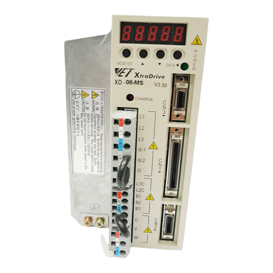
Are there any loose screws? Check screws for looseness using a screwdriver. If any of the above are faulty or incorrect, contact YET or an authorized distributor. 1.1.1. Servo Amplifiers External Appearance and Nameplate Examples... -
Page 19: Servo Amplifiers
XtraDrive User Manual Chapter 1: Checking Product and Part Names 1.2. Product Part Names This section describes product part names. 1.2.1. Servo Amplifiers The figure below shows the part names for servo amplifiers. -
Page 20: Model Numbers
Design Version # Blank, or 01-FF (optional) Blank, or R - Rack mounted, or V - Board coating (optional) Blank, or Y followed by 1 to 4 alphanumeric characters to identify customer applications (optional) Max. Applicable Max. Applicable Output Capacity Output Capacity... -
Page 21: Installation
XtraDrive User Manual Chapter 2: Inst a lla t i o n 2. Installation This chapter describes precautions for XtraDrive Series servomotor and servo amplifier installation. 2.1. Servo Amplifiers ..................2-2 2.1.1. Storage Conditions................2-2 2.1.2. Installation Site ...................2-2 2.1.3. Orientation ..................2-3 2.1.4. -
Page 22: Servo Amplifiers
Installation in a Control Panel method so the temperature around the servo amplifier does not exceed 55°C. Minimize heat radiated from the heating unit as well as any temperature rise caused by natural convection so the Installation Near a Heating Unit temperature around the servo amplifier does not exceed 55°C. -
Page 23: Orientation
The servo amplifier must be oriented this way because it is designed to be cooled by natural convection or by a cooling fan. Secure the servo amplifier using the mounting holes. The number of holes varies (from two to four) with the frame size of the servo amplifier. 2.1.4. - Page 24 XtraDrive User Manual Chapter 2: Installation Servo Amplifier Orientation Install the servo amplifier perpendicular to the wall so the front panels’ connectors faces outward. Cooling As shown in the figure above, allow sufficient space around each servo amplifier for cooling by cooling fans or natural convection.
-
Page 25: Wiring
XtraDrive User Manual Chapter 3: Wiring 3. Wiring This chapter describes the procedure used to connect XtraDrive Series products to peripheral devices and gives typical examples of main circuit wiring as well as I/O signal connections. 3.1. Connecting to Peripheral Devices...............3-2 3.1.1. -
Page 26: Connecting To Peripheral Devices
XtraDrive User Manual Chapter 3: Wiring 3.1. Connecting to Peripheral Devices This section provides examples of standard XtraDrive Series product connections to peripheral devices. It also briefly explains how to connect each peripheral device. -
Page 27: Single-Phase 200V Main Circuit Specifications
XtraDrive User Manual Chapter 3: Wiring 3.1.1. Single-Phase 200V Main Circuit Specifications... -
Page 28: Single-Phase 0.8Kw 200V Main Circuit Specifications
These devices have terminal B3 and internal regenerative resistor. Observe the following points. 1. Connect main power supply shown below to L1 and L3 terminals. Power supply is single-phase, 220 to 230 VAC +10% to –15%, 50/60Hz. If power supply of 187V (-15% of 220V) or less is used, alarm A.41 indicating voltage shortage, may occur... -
Page 29: Three-Phase 200V Main Circuit Specifications
XtraDrive User Manual Chapter 3: Wiring 3.1.3. Three-phase 200V Main Circuit Specifications... -
Page 30: Three-Phase 400V Main Circuit Specifications
XtraDrive User Manual Chapter 3: Wiring 3.1.4. Three-Phase 400V Main Circuit Specifications... -
Page 31: Xtradrive Internal Block Diagrams
XtraDrive User Manual Chapter 3: Wiring 3.2. XtraDrive Internal Block Diagrams The following sections show internal block diagrams of the servo amplifiers. 3.2.1. Single-phase 30W to 800W, 200V Models... -
Page 32: Three-Phase 1Kw To 3Kw, 200V Models
XtraDrive User Manual Chapter 3: Wiring 3.2.2. Three-phase 1kW to 3kW, 200V Models... -
Page 33: Three-Phase 0.5Kw To 3.0Kw, 400V Models
XtraDrive User Manual Chapter 3: Wiring 3.2.3. Three-phase 0.5kW to 3.0kW, 400V Models... -
Page 34: Main Circuit Wiring
Use twisted pair wires or multi-core shielded-pair wires for signal and encoder (PG) feedback lines. The maximum length is 3m (118.11 in) for reference input lines and is 20m (787.40 in) for PG feedback lines. Do not touch the power terminals for 5 minutes after turning power OFF because high voltage may still remain in the servo amplifier. -
Page 35: Names And Descriptions Of Main Circuit Terminal
L1 and L3. +10%, -15% Single-phase 220 to 230 VAC (50/60Hz) When a power supply of 187V(-15% of 220V) or less is used, an alarm 41, indicating voltage shortage, may occur when accelerating to max speed with max torque of motor. 3-11... -
Page 36: Typical Main Circuit Wiring Example
Designing a Power ON Sequence Note the following when designing the power ON sequence. Design the power ON sequence so that power is turned OFF when a servo alarm signal is output. (See the circuit figure above.) Hold the power ON button for at least two seconds. The servo amplifier will output a servo alarm signal for two seconds or less when power is turned ON. -
Page 37: Servo Amplifier Power Losses
400V XD-20-** XD-30-** 11.9 Note: Regenerative resistor power losses are allowable losses. Take the following action if this value is exceeded: Disconnect the internal regenerative resistor in the servo amplifier by removing the wire between terminals B2 and B3. Install an external regenerative resistor between terminals B1 and B2. -
Page 38: Wiring Main Circuit Terminal Blocks
Strip the end of the wire, leaving the ends twisted together. Open the wire insert opening of the terminal block (plug) with a tool using either of the two procedures shown in Fig. A and Fig. B on the following page. -
Page 39: I/O Signals
XtraDrive User Manual Chapter 3: Wiring 3.4. I/O Signals This section describes I/O signals for the XtraDrive servo amplifier. 3.4.1. Example of Typical I/O Signal Connections 3-15... -
Page 40: List Of Cn1 Terminals
(/COIN+) detection output Note: 1. Do not use unused terminals for relays. 2. Connect the shield of the I/O signal cable to the connector’s shell. 3. Connect to the FG (frame ground) at the servo amplifier-end connector. CN1 Specifications Applicable Receptacle Kit (YET P/N: 4J4003) -
Page 41: I/O Signal Names And Functions
5.2.1 supply is built into the servo amplifier). Note: 1. The functions allocated to /S-ON, /P-CON. P-OT, N-OT, /ALM-RST, /P-CL, and /N-CL input signals can be changed with parameters. (See 5.3.3 Input Circuit Signal Allocation.) 2. Pin numbers in parenthesis ( ) indicate signal grounds. -
Page 42: Output Signals
Note: 1. Pin numbers in parenthesis () indicate signal grounds. 2. The functions allocated to /TGON, /S-RDY, and /V-CMP (/COIN) can be changed via parameters. Functions /CLT, /VCT, /BK, /WARN, and /NEAR signals can also be changed. (See 5.3.4 Output Circuit Signal Allocation). -
Page 43: Interface Circuits
The maximum allowable voltage for input signals is ±12V. Reference Position Input Circuit An output circuit for the reference pulse and error counter clear signal at the host controller can be either line-driver or open-collector outputs. These are shown below by type. - Page 44 XtraDrive User Manual Chapter 3: Wiring The following examples show how to select the pull-up resistor R1 so the input current (I) falls between 7 and 15mA. Application Examples R1 =2.2kΩ with R1 =1kΩ with R1 =180Ω with = 24V ±5% = 12V ±5%...
- Page 45 Chapter 3: Wiring Output Circuit Interfaces Any of the following three types of servo amplifier output circuits can be used. Connect an input circuit at the host controller following one of these types. Connecting to a Line-driver Output Circuit Encoder serial data converted to two-phase (A and B phase) pulse...
- Page 46 XtraDrive User Manual Chapter 3: Wiring • Connecting an optocoupler output circuit An optocoupler output circuits are used for servo alarm, servo ready, and other sequence output signal circuits. Connect an optocoupler output circuit through a relay or line receiver circuit.
-
Page 47: Wiring Encoders (For Sgmgh And Sgmsh Motors Only)
Encoder Connections The following diagrams show the wiring of the encoder output from the motor to CN2 of the servo amplifier, and PG output signals from CN1 to the controller. This applies to both incremental and absolute encoders of SGMGH and SGMSH motors only. - Page 48 XtraDrive User Manual Chapter 3: Wiring Absolute Serial Encoders Incremental A/B+C Encoders 3-24...
-
Page 49: Cn2 Encoder Connector Terminal Layout And Types
Soldered Plug Case (Servomotor Connector Side) 10320-52A0-008 54280-0600 6PIN 10220-52A2JL MDR 10120-3000VE 20PIN 20 PIN (YET P/N: 4J4001) (YET P/N: J0101) (YET P/N: J1521) Note: The motor-end relay socket connects to the encoder connector for the SGMAH and SGMPH servomotors. 3-25... -
Page 50: Encoder Cables Interconnections
Chapter 3: Wiring 3.5.3. Encoder Cables Interconnections This chapter shows interconnections for all standard encoder cables available from YET (Refer to YET Part Number). For additional types of encoders (like with communication sensors etc.) contact your YET representative. Absolute A/B Encoder Cable For Yaskawa SGM motors. - Page 51 XtraDrive User Manual Chapter 3: Wiring Absolute Serial Encoder Cable For Yaskawa SGMAH motors. (P/N 004139) XtraDrive side Motor side 20-pin connector 6-pin connector SPG5V 10 1 PG5V Battery BLACK SPG0V 11 2 GND connector ORANGE BAT+ 1 3 PGBAT+...
-
Page 52: Examples Of Standard Connections
These devices have terminal B3 and internal regenerative resistor. Observe the following points. 1. Connect main power supply shown below to L1 and L3 terminals. Power supply is single-phase, 220 to 230 VAC +10% to –15%, 50/60Hz. If power supply of 187V (-15% of220V) or less is used, alarm A41 indicating voltage shortage, may occur when accelerating to max speed with max torque of motor. - Page 53 Position Control Mode *1. P represents twisted-pair wires *7. These circuits are SELV circuits, therefore are *2. The time constant for the primary filter is 47us. separated from all other circuits by double and *3. Connect only with an absolute encoder.
- Page 54 Speed Control Mode *1. P represents twisted-pair wires *7. These circuits are SELV circuits, therefore are *2. The time constant for the primary filter is 47us. separated from all other circuits by double and *3. Connect only with an absolute encoder.
- Page 55 *1. P represents twisted-pair wires *7. These circuits are SELV circuits, therefore are separated from all other circuits by double and *2. The time constant for the primary filter is 47us. reinforced insulator. *3. Connect only with an absolute encoder.
- Page 56 XtraDrive User Manual Chapter 3: Wiring This page intentionally left blank. 3-32...
- Page 57 XtraDrive User Manual Chapter 4: Trial Operation 4. Trial Operation This chapter describes a two-step trial operation. Be sure to complete step 1 before proceeding to step 2. 4.1. Two-Step Trial Operation ................4-2 4.1.1. Step 1: Trial Operation for Servomotor without Load......4-3 4.1.2.
-
Page 58: Trial Operation
4.1. Two-Step Trial Operation Make sure that all wiring is completed prior to starting trial operation. For your own safety, perform the trial operation in the order given below (step 1 and 2). See 4.1.1 Trial Operation for Servomotor without Load and 4.1.2 Trial Operation for Servomotor Connected to Mashine for more details... -
Page 59: Step 1: Trial Operation For Servomotor Without Load
1 (prior to connecting the servomotor to equipment). Note: Check the items on the following pages in the order given during the servomotor trial operation. See 4.2.1 Servomotors with Brakes, if you are using a servomotor with brakes. - Page 60 In this case, turn OFF power and take appropriate action. See 9.2 Troubleshooting. Note: If an absolute encoder is used, it must be set up. Refer to 5.7.4 Absolute Encoder Setup.
- Page 61 Check input signal wiring in Monitor Mode using the panel operator. See 7.1.6 Operation in Monitor Mode for more details on the procedure. Turn ON and OFF each signal line to see if the LED monitor bit display on the panel changes as shown below. Input signal LED display...
- Page 62 CN1-47 signals. Note: IF an absolute encoder is being used, the servo will not turn ON when the servo ON signal (/S-ON) is input unless the SEN signal is also ON. When the SEN signal is checked in Monitor mode, the top of the LED will light because the SEN signal is high when ON.
- Page 63 If an alarm display appears, take appropriate action as described in 9.2 Troubleshooting. Note: If there is noise in the reference voltage for speed control, the “-” on the left of the 7-segment LED may flash.
- Page 64 Operating Procedure In Position Control Mode: Set Pn000.1 to 1 1. Set the parameter Pn200.0 so that the reference pulse form is the same as the host controller output form. To select the reference pulse form: See 5.2.2 Position Reference.
-
Page 65: Step 2: Trial Operation With Servomotor Connected To Machine
Set parameters as required and record all settings for later use during maintenance. Note: The servomotor will not be broken in completely during the trial operation. Therefore, let the system run for a sufficient amount of time after trial operation has been completed to ensure that it is properly broken in. -
Page 66: Additional Setup Procedures In Trial Operation
Servomotor from rotating due to gravity. Note: To prevent faulty operation when using gravity or external force, first make sure that both the servomotor and the holding brake work properly. When assured that each operates properly, connect the servomotor to the rest of the equipment to start the trial operation. -
Page 67: Position Control By Host Controller
Chapter 4: Trial Operation 4.2.2. Position Control by Host Controller If the position control algorithm of the host controller has not been established or finalized, disconnect the servomotor from the equipment before performing a trial operation. This will prevent the servomotor from running out of control and damaging the equipment. -
Page 68: Basic Parameters
See 5.2.5 Changing Servomotor Rotation Direction If the specified direction differs from the actual direction of rotation, wiring may be incorrect . Recheck the wiring and correct if necessary. Use the following parameter to reverse the direction of rotation. Pn000.0 Switching Servomotor Rotation Direction See 5.1.1... -
Page 69: Parameter Settings And Functions
5.4.4. Using the Holding Brake ..............5-58 5.5. Forming a Protective Sequence ..............5-61 5.5.1. Using Servo Alarm and Alarm Code Outputs ........5-61 5.5.2. Using the Servo ON Input Signal (/S-ON) ........5-63 5.5.3. Using the Positioning Completed Output Signal (/COIN) ....5-64 5.5.4. - Page 70 5.9.1.5. Setting Default Motion Profile Parameters........5-94 5.9.1.6. Profile Speed (Pn2A2, Pn2A3) .............5-95 5.9.1.7. Profile Acceleration (Pn2A4, Pn2A5) ..........5-95 5.9.1.8. Jerk Smoothing Time (Pn2A6) .............5-95 5.9.1.9. Quick Stop Deceleration (Pn2A8, Pn2A9) ........5-96 5.9.1.10. Motion End Window (Pn2C0) ............5-96 5.9.2. Torque Control..................5-96 5.9.3.
-
Page 71: Parameters
Chapter 5: Parameter Settings and Functions Before Reading This Chapter This chapter describes the use of each CN1 connector I/O signals in the XtraDrive servo amplifier as well as the procedure for setting the related parameters for the intended purposes. -
Page 72: Settings According To Device Characteristics
XtraDrive User Manual Chapter 5: Parameter Settings and Functions 5.1. Settings According to Device Characteristics This section describes the procedure for setting parameters according to the dimensions and performance characteristics of the equipment used. 5.1.1. Switching Servomotor Rotation Direction XtraDrive has a Reverse Rotation mode that reverses the direction of servomotor rotation without rewiring. -
Page 73: Setting The Overtravel Limit Function
Forward rotation end Servomotor XtraDrive CN1 -42 P- OT N - OT CN1 -43 The drive status with an input signal ON or OFF is shown in the following table. Signal State Input Level Description Forward rotation allowed, (normal CN1-42: low operation status). - Page 74 CN1-42 to 0V). Inputs the reverse signal from CN1-42 Example: B input terminal. For more options of parameters Pn50A.3 and Pn50B.0 refer to Appendix D.3. Input Signal Selections Uses the N-OT input signal to prevent reverse rotation. (Reverse rotation is...
- Page 75 Pn001.1 = 1 or 2 Coast status Note: For torque control, the servomotor will be placed in coast status after either decelerating or coasting to a stop (according to the stop mode set in Pn001.0), regardless of the setting of Pn001.1.
-
Page 76: Limiting Torque
Output signal monitor Torque limits are specified as a percentage of the rated torque. Note: If the torque limit is set higher than the maximum torque of the servomotor, the maximum torque of the servomotor is the limit. Application Example: Equipment Protection... - Page 77 Note: Multiple signals allocated to the same output circuit are output using OR logic. Set other output signals to a value other than the one allocated to the /CLT signal in order to use just the /CLT output signal. See...
- Page 78 XtraDrive User Manual Chapter 5: Parameter Settings and Functions Setting Level 2: External Torque Limit A contact input signal is used to enable the torque (current) limits previously set in parameters. Torque limits can be set separately for forward and reverse rotation.
- Page 79 Range: 0 to 800 Pn405 Reverse External Torque Limit Control, Default Setting: 100 Position Control Set the torque limits when the torque is limited by an external contact input. Signal Description /P-CL (CN1-45) Input Pn404 torque limit applied. /N-CL (CN1-46) Input Pn405 torque limit applied.
-
Page 80: Settings According To Host Controller
Input SG CN1-6 The above inputs are used for speed control (analog reference). (Pn000.1 = 0, 4, 7, 9, or A.) Always wire for normal speed control. Refer to 7.1.6 Operation in Monitor Mode. The motor speed is controlled in proportion to the input voltage between V-REF and SG. - Page 81 (V) The default setting is adjusted so that a 6V input is equivalent to the rated motor speed of all applicable servomotors. Note: The maximum allowable voltage to the speed reference input (between CN1-5 and 6) is ± 12V 5-13...
-
Page 82: Position Reference
This method can prevent the occurrence of overshoot and also shorten settling time. • If PI control mode is used when the speed reference has a reference offset, the motor may rotate at a very slow speed and fail to stop even if 0 is specified as speed reference. - Page 83 Applicable line driver: SN75174, manufactured by Texas Instruments Inc., MC3487 or equivalent Ω Connection Example 2: Open-collector Output Set limiting resistor R1 so that input current I falls within the following range: Ω The examples below show how to select the pull-up resistor R1 so that the input current I falls between 7 and 15mA.
- Page 84 Ω Ω Note: The noise margin of the input signal will decrease if the reference pulse is provided by an open- collector output. Set parameter Pn200.3 to 1 if the position drifts due to noise. Selecting a Reference Pulse Form Use the following parameters to select the reference pulse form used.
- Page 85 (CN1-11) (CN1-11) Input Pulse Multiplier The input pulse multiplier function can be used if the reference pulse is a two-phase pulse train with a 90° phase differential. The electronic gear function can also be used to convert input pulses. 5-17...
- Page 86 Example of I/O Signal Generation Timing µ Note: 1. For the input pulse to register, the interval from the time the servo ON signal is turned ON until a reference pulse is entered must be a minimum of 40ms. 2. The error counter clear signal must be ON for at least 20µs.
- Page 87 • The error counter inside the servo amplifier is set to 0. • Position loop control is prohibited. Use this signal to clear the error counter of the host controller or select the following clear operation through parameter Pn200.1. Parameter...
-
Page 88: Using The Encoder Signal Output
Note: Dividing means converting an input pulse train from the encoder mounted on the servomotor according to the preset pulse density and outputting the converted pulse. The units are pulses per revolution (PPR). I/O Signals I/O signals are described below. - Page 89 If the configuration of the mechanical system prevents turning the servomotor before the origin return operation, then perform the origin return operation at a servomotor speed of 600rpm or below. The phase C pulse signal may not be correctly applied if the servomotor turns faster than 600rpm.
- Page 90 Note: 1. Turn OFF power once and turn ON again after changing the parameter. 2. A 13-bit encoder will run at 2048PPR even if the setting at Pn201 is set higher than 2049. A quad B Encoder - Setting of the pulse-dividing ratio.
-
Page 91: Sequence I/O Signals
Connect these signal terminals as required. Input Signal Connections Connect the sequence input signals as shown below. Note: Provide a separate external I/O power supply; the servo amplifier does not have an internal 24V power supply. External power supply specifications: 24V ±1 V , 50mA minimum. - Page 92 Connect the sequence output signals as shown in the following figure. Note: Provide a separate external I/O power supply; the servo amplifier does not have an internal 24V power supply. It is recommended to use the same type of external power supply as the one used for input circuits.
-
Page 93: Using The Electronic Gear Function
32768 16-bit 16384 Absolute encoder 17-bit 32768 Note: The number of bits representing the resolution of the applicable encoder is not the same as the number of encoder signal pulses (A and B phase) output from the servo amplifier. 5-25... - Page 94 0.01 ≤ Electronic gear ratio ≤ 100 The servo amplifier will not work properly if the electronic gear ratio exceeds this range. In that case, modify either the load configuration or the reference unit. 5-26...
- Page 95 XtraDrive User Manual Chapter 5: Parameter Settings and Functions 5. Set the parameters. Reduce the electronic gear ratio to lower terms so that both A and B are integers smaller than 65535, then set A and B in the respective parameters:...
- Page 96 Travel distance per load shaft revolution = 0010 12566 16384 Electronic gear ratio 12566 196608 20480 12566 1309 Preset Pn202 20480 Values Pn203 1309 Control Block Diagram The following diagram illustrates a control block for position control. 5-28...
-
Page 97: Contact Input Speed Control
User constants are not required. cons tant. Using Contact Input Speed Control Follow steps 1 to 3 below to use the contact input speed control function. 1. Set contact input speed control as shown below. Parameter Signal... - Page 98 Note: 1. 0: OFF (high level); 1: ON (low level) 2. /P-CON, /P-CL and /N-CL functions differ from those in the table above when Pn000.1 is set to 3, 4, 5, or 6. The function is switched automatically when Pn50A. 0 is set to 0.
- Page 99 Input /P-CL CN1-45 (Forward External Torque Limit Position Control Input) Speed Selection 2 Speed/Torque Control, Input /N-CL CN1-46 (Reverse External Torque Limit Position Control Input) Note: Position Control is used here only by Pulse Reference, not by Serial Command 5-31...
- Page 100 When contact input speed control is not used, input signals are used as external torque limit inputs. Note: The contact input speed control function is used only when signals are allocated to /SPD-D, /SPD-A, and /SPD-B. Selection of Rotation Direction The input signal /P-CON(/SPD-D) is used to specify the direction of servomotor rotation.
- Page 101 Note: 1. The above figure illustrates signal generation timing when the soft start function is used. 2. The value of t1 is not affected by the use of the soft start function. A maximum 2ms delay occurs when the /PC-L(/SPD-A) or /N-CL(/SPD-B) signal is read.
-
Page 102: Using Torque Control
(external torque limit). • Level 3: Controls torque output rather than speed output. • Level 4: Switches between speed and torque control. The following describes uses for levels 3 and 4 in the torque control function. Torque Control Selection Set the following parameter to select the type of control described in levels 3 and 4. - Page 103 Speed reference input V-REF (CN1-5) cannot • S peed V-R E F Cn1-5 L imit be used for speed control if Pn002.1 is set to 1. Parameter Pn407 can be used for maximum • speed control. Application Example S ervo amplifier Torque Control <->...
- Page 104 Parameter Parameter /P-CL (/SPD-A) /N-CL (/SPD-B) CN1-45 CN1-46 State State Torque Control Speed Control (Contact reference) Note: Input signal /C-SEL can be used only when a signal is allocated to the input circuit. See 5.3.3 Input Circuit Signal Allocation. 5-36...
-
Page 105: Default Settings
Input SG CN1-10 Speed/Torque Control Reference Input These signals are used when torque control is selected. Servomotor torque is controlled so that it is proportional to the input voltage between T-REF and SG. Reference torque (%) Factory s etting -100... - Page 106 3, 4, 5, 6 Switches the direction of rotation in Contact Input Speed Control mode. 7, 8, 9 Switches the control mode. Turns ON/OFF zero clamp. Turns inhibit ON/OFF. Note: The /P-CON signal function switches automatically when Pn50A.0 is set to 0. 5-38...
- Page 107 This parameter sets the voltage range for torque reference input T-REF (CN1-9) depending on the output range of the host controller or external circuit. The default setting is 30, so the rated torque output is equal to 3V (30 × 0.1). Reference torque...
-
Page 108: Torque Feed-Forward Function
XtraDrive User Manual Chapter 5: Parameter Settings and Functions The maximum speed of the servomotor will be used if Pn407 is set to a value higher than the maximum speed of the servomotor. External Speed Limit Function: This function sets the voltage range for speed reference input V-REF (CN1-5) according to the output range of the host controller or external circuit. - Page 109 Limiting by Analog Voltage Reference. Setting Torque feed-forward is set using parameter Pn400. The default setting at Pn400 is 30. If, for example, the torque feed- forward value is ±3V, then the torque is limited to ±100% of the rated torque. Setting Parameter...
-
Page 110: Torque Limiting By Analog Voltage Reference
10). It cannot be used for torque control because the torque reference input terminal T-REF is used as an input terminal. The torque is limited at the forward run side when the P-CL signal turns ON and at the reverse run side when the N-CL signal turns ON. - Page 111 Setting The torque limit is set using parameter Pn400. The default setting for Pn400 is 30. If, for example, the torque limit is ±3V, then torque is limited to 100% of the rated torque. (A torque value higher than 100% torque is clamped at 100%.)
-
Page 112: Reference Pulse Inhibit Function (/Inhibit)
Prohibits the servo amplifier from counting reference pulses. The servomotor remains locked. Note: Parentheses ( ) around an /INHIBIT signal indicate that a signal has been allocated to the input circuit. See 5.3.3 Input Circuit Signal Allocation for more details. 5-44... -
Page 113: Setting Up The Servo Amplifier
Enable monitoring the motor speed and Un000 to Un00D torque reference on the panel display. Note: Appendix B shows a list of parameters provided for reference. See 7.1.5 Operation in Parameter Setting Mode for more details on the parameter setting procedure. 5-45... -
Page 114: Jog Speed
Reverse run prohibit /ALM-RST Alarm reset (Forward current limit) /P-CL (Reverse current limit) /N-CL Note: * The functions of these input signals are automatically switched according to the setting for parameter Pn000.1 as long as Pn50A.0 is set to 0. 5-46... - Page 115 Description Default setting for sequence input signal allocation. Enables any sequence input signal settings. Note: The default setting for parameter Pn50A.0 is 0. Functions and applications in this manual are generally described for the factory defaults. Input Signal Allocation The following signal can be allocated when Pn50A.0 is set to 1.
- Page 116 Note: Several signals can be allocated to the same input circuit. When the servo is ON, the forward run prohibit or reverse run prohibit signal is used. At a setting with inverted polarity, the failed safe operation may not be possible in the case of signal line disconnection.
- Page 117 (/C-SEL) Zero Clamp Pn50D.0 (/ZCLAMP) Reference (low level) Pulse Inhibit Pn50D.1 (/INHIBIT) Gain Switching Pn50D.2 (/G-SEL) Note: *Same as above” means that input signals and terminals SI0 to SI6 are enabled or disabled through parameter settings 0 to 8. 5-49...
-
Page 118: Output Circuit Signal Allocation
XtraDrive User Manual Chapter 5: Parameter Settings and Functions 5.3.4. Output Circuit Signal Allocation Output Signal Allocation Output signal functions can be allocated to the sequence signal output circuits shown below. Default Setting CN1 Connector Output Terminal Terminal Comments Symbol... - Page 119 — — — Note: Signals are output with OR logic when multiple signals are allocated to the same output circuit. Signals that are not detected are invalid. For example, the positioning completed signal /COIN is invalid in Speed Control mode.
-
Page 120: Control Mode Selection
Chapter 5: Parameter Settings and Functions 5.3.5. Control Mode Selection The XtraDrive servo amplifier offers speed control, position control, torque control, and the other control modes shown in the following table. The following parameter is used to set the control mode. Parameter... - Page 121 (A) Speed Control (Analog Reference) Zero Clamp This speed control mode is used to set the zero clamp function when the servo amplifier is stopped. Zero clamp operates when the /P-CON (/ZCLAMP) signal is ON (low level). See 5.4.3 Using the Zero Clamp Function.
-
Page 122: Setting Stop Functions
Adjusting Offset When the Servomotor Will Not Stop The servomotor may rotate at very low speed and not stop even when 0V is specified as the reference voltage for servo amplifier speed and torque control (analog reference). This happens when the reference voltage from the host controller or external circuit is slightly offset (in mV units). -
Page 123: Servo Off Stop Mode Selection
Reference Offset to a specified value. Note: Use manual rather than automatic adjustment if a position control loop is formed in the host controller. See the following sections in Chapter 7 Using the Panel Operator for more details on adjustment procedures:... -
Page 124: Using The Zero Clamp Function
30 to 1500W for 200V 2.0 to 3.0kW for 400V If the DB circuit needs to be turned OFF when the main power supply or the control power supply is OFF, disconnect the servo amplifier’s wiring (U, V, and W). - Page 125 Speed/Torque Control, Input /P-CON CN1-41 Proportional Control, etc. Position Control Note: The /ZCLAMP signal can be used when an input circuit signal is allocated. See 5.3.3 Input Circuit Signal Allocation for more details. Pn000.1 Setting Control Mode Zero Clamp Control Mode...
-
Page 126: Using The Holding Brake
Open (OFF) (ON) /P-CON (/ZCLAMP) input Zero clamp is performed Note: When the /ZCLAMP signal is allocated, the zero clamp operation will be used even for speed control (Pn000.1 = 0). 5.4.4. Using the Holding Brake The holding brake is used when a XtraDrive controls a vertical axis. In other words, a servomotor with brake prevents the movable part from shifting due to the force of gravity when system power goes OFF. - Page 127 Note: Signals are output with OR logic when multiple signals are allocated to the same output circuit. Set other output signals to a value other than the one allocated to the /BK signal in order to output the /BK signal alone. See 5.3.4 Output Circuit Signal Allocation.
- Page 128 This setting sets the brake ON timing when the servomotor is stopped. Use Pn507 and 508 for brake ON timing during operation. Note: The servomotor will turn OFF immediately if an alarm occurs. The equipment may move due to gravity in the time it takes for the brake to operate.
-
Page 129: Forming A Protective Sequence
• Motor speed drops below the setting at Pn507 after servo OFF. • The time set at Pn508 has elapsed since servo OFF. The actual speed used will be the maximum speed even if Pn507 is set higher than the maximum speed. - Page 130 These alarms are output when a servo amplifier alarm is detected. XtraDrive Alarm ALM output detection Turns power OFF. Form an external circuit so that this alarm output (ALM) turns OFF the servo amplifier. State Status Result Circuit between CN1-31 and 32 is closed, and Normal state.
-
Page 131: Using The Servo On Input Signal (/S-On)
OFF. Alarms can also be reset using a panel or digital operator. Note: 1. Encoder alarms cannot always be reset by inputting the /ALM-RST signal. In that case, turn the control power supply OFF to reset the alarm. -
Page 132: Using The Positioning Completed Output Signal (/Coin)
Output /COIN CN1-25 Position Control Signal This signal indicates that the servomotor movement during position control has been completed. The host controller uses the signal as an interlock to confirm that positioning is completed. Reference speed Motor speed Speed Time... -
Page 133: Speed Coincidence Output (/V-Cmp)
Position Control Default Setting: 7 Note: *Reference units for this parameter are the number of input pulses as defined using the electronic gear function; if a Serial Command is used, it is defined in Position Units. This parameter is used to set output timing for the positioning completed signal (/COIN) when the position reference pulse is input and servomotor operation is completed. - Page 134 Chapter 5: Parameter Settings and Functions Speed Coincidence Output Output /V-CMP CN1-25 Speed Control Signal This signal is output when the actual motor speed during speed control is the same as the speed reference input. /V-CMP State Status Result Circuit between CN1-25 and 26 is Speed coincides.
-
Page 135: Using The Running Output Signal (/Tgon)
The /V-CMP signal is output when the difference between the speed reference and actual motor speed is below this setting. Example: The /V-CMP signal turns ON at 1900 to 2100rpm if the parameter is set to 100 and the reference speed is 2000rpm. -
Page 136: Using The Servo Ready Output Signal (/S-Rdy)
Control, Position Default Setting: 20 Control This parameter is used to set the speed at which the servo amplifier determines that the servomotor is running and then to output an appropriate signal. The following signals are generated when motor speed exceeds the preset level. -
Page 137: Using The Warning Output Signal (/Warn)
Pn50E Output Signal Selections 1 Default Setting: 3211 Position Control The parameter is factory set so the /V-CMP signal is output between CN1-29 and 30. See 5.3.4 Output Circuit Signal Allocation for more details on parameter Pn50E. 5.5.7. Using the Warning Output Signal (/WARN) This section describes the basic use and wiring procedure for the warning (/WARN) output signal (photocoupler output signal). - Page 138 Multiple signals allocated to the same output terminal follow Boolean OR logic. In order to use the /WARN output signal alone, set other output signals to a value other than the one allocated to the /WARN signal. See 5.3.4 Output Circuit Signal Allocation.
-
Page 139: Handling Power Loss
In power loss detection, the status of the main circuit power supply is detected and OFF status is ignored so that the servomotor’s operation will continue if motor power turns back ON within the time set at user constant Pn509. -
Page 140: Selecting A Regenerative Resistor
XD-20DE to -30DE 400V Note: The amount of regenerative power (average value) that can be processed is rated at 20% of the capacity of the servo amplifier’s built-in regenerative resistor. When installing an external regenerative resistor, make sure that the resistance is the same as that of the servo amplifier’s built-in resistor. -
Page 141: External Regenerative Resistor
“10” (10 x 10W = 100W) Note: 1. In general, when resistors for power are used at the rated load ratio, the resistor temperature increases to between 200°C and 300°C. The resistors must be used at or below the rated values. -
Page 142: Calculating The Regenerative Power Capacity
Servo Amplifiers with a Capacity of 400W or Less Servo amplifiers with a capacity of 400W or less do not have built-in regenerative resistors. The energy that can be absorbed by capacitors is shown in the following table. If the rotational energy in the servo system exceeds these values, then connect a regenerative resistor externally. - Page 143 — — SGMUH — — — — — — Operating Conditions for Allowable Regenerative Frequency Calculation Use the following equation to calculate the allowable frequency for regeneration mode operation. Allowable frequency servomotor only rotation speed Cycles ...
- Page 144 20%. If the previous calculation determines that the amount of regenerative power (W ) that can be processed by the built-in resistor is not exceeded, then an external regenerative resistor is not required. 5-76...
- Page 145 XtraDrive User Manual Chapter 5: Parameter Settings and Functions If the amount of regenerative power that can be processed by the built- in resistor is exceeded, install an external regenerative resistor for the capacity obtained from the above calculation. If the energy consumed by load system loss (in step 2 above) is unknown, then perform the calculation using E = 0.
-
Page 146: Absolute Encoders
(+32767) and begins counting down (toward zero and beyond). Note: After the limit has been changed in the multi-turn limit setting parameter (Pn205), the power must be cycled. This generates a Multi-turn Limit Disagreement Alarm (A.CC). Make sure that the entered value is appropriate before resetting this alarm. -
Page 147: Interface Circuit
ON signal (/S-ON). Note: If for some reason it is necessary to turn OFF a SEN signal that is already ON, and then to turn it back ON again, maintain the high level for at least 1.3 seconds before turning it ON and OFF. -
Page 148: Configuring An Absolute Encoder
• With any other Pn205 value entered, data varies from 0 to the set value. Note: To activate reassignment of this value, the user must first enter the change to the parameter, and then cycle (turn OFF and then turn ON) the power. -
Page 149: Absolute Encoder Setup
(Fn-013). This operation can be executed using the hand-held digital operator or the servo amplifier panel operator. Note: The multi-turn limit setting is enabled only during the multi-turn limit value mismatch alarm. Cycle the power after performing this operation. WARNING Connect the ground terminal to a class-3 ground (100Ω... - Page 150 They cannot be cleared by the servo amplifier’s alarm reset (/ARM-RST) input signal. • Encoder backup alarm (A.81) • Encoder check sum alarm (A.82) In addition, if a monitoring alarm is generated in the encoder, the alarm must be cleared by turning OFF the power. 5-82...
- Page 151 If the Multi-turn Limit Value Disagreement Alarm occurs, check the setting of parameter • Pn205 in the servo amplifier to be sure that it is correct. If Fn013 is executed when an incorrect value is set in Pn205, that same incorrect value will be set in the encoder. There will not be an additional alarm, even if an incorrect value is set, but incorrect positions will be detected.
-
Page 152: Absolute Encoder Reception Sequence
5.7.4. Absolute Encoder Reception Sequence This section describes the sequence in which the servo amplifier receives data from the absolute encoder and transmits it to the host device. Be sure you understand this section when designing the host device. Outline of Absolute Signals The absolute encoder’s outputs are PAO, PBO, PCO, and PSO signals... - Page 153 M = The multi-turn data (rotation count data). = The number of initial incremental pulses. = The number of initial incremental pulses read at setup. (This is saved and controlled by the host controller). = The current value required for the user’s system.
- Page 154 Note: Data is “P+00000” (CR) or “P-00000” (CR) when the number of revolutions is zero. The revolution range is “+32767” to “-32768.” When this range is exceeded, the data changes from “+32767” to “-32768” or from “-32768” to “+32767” PSO Serial Data Specifications The number of revolutions and the absolute position within one revolution are always output in five and seven digits, respectively.
- Page 155 Pulses from the motor encoder (PG) are divided by the number of pulses set here before being output. The set value is the number of output pulses per revolution. Set this value according to the reference unit of the machine or controller to be used.
- Page 156 PAO outputs to the host device as serial data. Alarm Contents Output Example "H" Error detection "L" SEN Signal Absolute encoder backup Digital Operator Display alarm ALM81 PAO Serial Data Incremental pulses Note: Refer to 9.2.3 Alarm Display Table for a table of alarm contents 5-88...
-
Page 157: Ab Encoders
Results C-pulse used C-pulse not used Set the resolution of A quad B encoder in Pn192, Pn193. Note that the value in Pn192 should be set as the physical (optical) resolution, excluding the x4 multiplication done by the driver internally. - Page 158 XtraDrive User Manual Chapter 5: Parameter Settings and Functions Set the direction of electrical phase. This parameter used to find the electrical phase in the AB encoder (other than Yaskawa); if you don’t know the direction, just set unknown direction and XtraDrive will find it automatically.
-
Page 159: Configuration Of Serial Commands For Ab Encoders
The number need not be an integer. The maximum value of numerator (Pn2B0) or denominator (Pn2B2) is 65535. In cases where greater values are required, it is possible to use parameters Pn2B1 and Pn2B3 for storing the high bits of numerator and... -
Page 160: Speed Units
XtraDrive User Manual Chapter 5: Parameter Settings and Functions Example: A rotary motion system uses a motor with a 17-bit encoder. The user wants to program the system in units of 0.1 degree: 17-bit encoder produces 131072 [counts] per revolution. -
Page 161: Acceleration Units
XtraDrive User Manual Chapter 5: Parameter Settings and Functions Example: A rotary motion system uses a motor with a 17-bit encoder. The user wants to program the system in speed units of rpm: 17-bit encoder produces 131072[counts] per revolution. U=131072... -
Page 162: Setting Default Motion Profile Parameters
Without reduction of the fraction: High Bits = HB = Integer part of N/65536 = Integer part of 131072/65536 = 2 Low Bits = N – HB * 65536 = 131072 – 2 * 65536 = 0 Pn2B8 = 0 Pn2B9 = 2... -
Page 163: Profile Speed (Pn2A2, Pn2A3)
This variable is used to define the jerk smoothing time of a movement, i.e., it uses an average filter on the command pattern. For example, if the command pattern is a trapeze, it will make it a S-curve pattern. -
Page 164: Quick Stop Deceleration (Pn2A8, Pn2A9)
This variable defines the default value of a window for position error to finish a motion. In case of a MOVED motion, the next motion in buffer will be executed after the command is finished and the position error (in user units) will be smaller than the value of this variable. -
Page 165: Homing
If after home (in absolute encoder), the command SET ZERO POSITION does not execute, then no offset is added to encoder. It is possible to find home in two ways: either by a limit switch or by an obstacle (hard home). Hard home is found if two conditions are valid: if... -
Page 166: Digital I/O
Set Emergency always ON (default) Note: In case of Pn2D1.0=8 you cannot set servo ON, because Emergency is always ON. In addition to digital output parameters Pn50E – Pn50F, there is one more output for serial command defined in Pn2D2 that work in the same way and can be related in the program. -
Page 167: Auto Tuning
-Pn2C9 5.10. Auto Running a User Program After downloading a user program to the driver, it is possible to run it automatically every time the driver turns ON, by setting the parameter Pn2CC to the program label number which the program start with. With the default setting 0 the program auto running is disabled. -
Page 168: Servo Adjustment
XtraDrive User Manual Chapter 6: Servo Adjustment 6. Servo Adjustment This chapter describes the functions required for servo adjustment. Find the required information by selecting the section from the following table of contents. 6.1. Selection of Control Mode................6-2 6.2. Analog Input or Contact Input Velocity Control ........6-3 6.2.1. -
Page 169: Selection Of Control Mode
Adjustment of Speed Control using Analog Input or Contact Input is described below in section 6.2, for setting cases of Pn000.1 = 0, 3, 6, 9 and A. Adjustment for Position Control or NCT Velocity Control is described below... -
Page 170: Analog Input Or Contact Input Velocity Control
This section provides technical information for operation of servomotors in Velocity Control mode with Analog Input. The Identical Control principle is applied in case of Contact Input or Analog Input. In case of Contact Input, the velocity command value is retrieved from one of the predefined values, according to the Contact Input setting. -
Page 171: Parameters Of The Velocity Control
Setting the Input Gain Parameter 300 defines the ratio between Analog Voltage and equivalent speed command. Normally, this parameter should be set so that a 10Volt input will produce a speed command slightly superior to the maximum allowable speed of the system. -
Page 172: Adjusting Offset
• Reference offset automatic adjustment • Reference offset manual adjustment If a position loop is formed in the host controller, be sure to make a manual offset adjustment and no automatic reference offset adjustment. Refer to the following sections in Chapter 7 Using the Panel Operator for a detailed description of reference offset adjustment. -
Page 173: Using The Soft Start Function
Set both Pn305 and Pn306 to “0” for normal speed control, i.e when the speed reference does not need to be smoothed. Set these parameters as follows: •... -
Page 174: Load Inertia Setting
6.2.6. Load Inertia Setting In order to use values of Loop Gains that are closely related to the characteristics of your system, loop gains are normalized in Hertz. This normalization of parameters is done according to the assumed inertia of the system. -
Page 175: Adjusting Speed Loop Gain
XtraDrive. Refer to Section 6.4 The tuning procedure is as follows: 1. Start with a Ti at maximum value and a low value of Kv, so that system will be stable upon Servo Enabling. 2. Enable the Servo, then progressively rise the value of Kv, until oscillations or overshoots are observed. -
Page 176: Setting The Torque Reference Filter Time Constant
There is, however, a limit, depending on machine conditions. In order to find the optimal value of the torque filter, repeat steps 1 and 2 of previous section for each new try of the torque filter. Finally select the optimal torque filter value as the one who results in the highest Kv. -
Page 177: Gain Setting Reference Values
Refer to these values and use the previously mentioned methods to make gain adjustments. These values are for reference only and do not mean that the mechanical system has good response characteristics or is free from oscillation in the specified ranges. - Page 178 When the inertia ratio is much larger, start the gain adjustments with the position and speed • loop gains set to the smallest values and the speed loop integral constant to the largest value in the ranges given above. In speed control operation, the position loop gain is set through the host controller.
-
Page 179: Nct Position Control
In case more precise tuning is desired, this first set can be used as a starting point You can do a rough estimation of the inertia of the load for your system and input its value in the Load Inertia Ratio parameter (Pn103). - Page 180 XtraDrive User Manual Chapter 6: Servo Adjustment The following wizard will help you to calculate your load inertia. Estimation of Equivalent Load ( J load Case 1_ Load is a cylinder directly mounted or coupled to motor axis: π × ρ ×...
-
Page 181: Position Control Block Diagram
Chapter 6: Servo Adjustment 6.3.2. Position Control Block Diagram The following is a general block diagram of the NCT. The NCT algorithm includes specific non-linear functions for each one of the blocks shown here, so that this block diagram should be used for general understanding only. -
Page 182: Nct Gain Parameters
However, the increase is limited by the flexibility of the mechanical system driven. A too high value of Kd will cause high frequency oscillations of the system. For tuning, raise the value of that parameter progressively until oscillations are observed or acoustic noise is heard. -
Page 183: Oca - Oscillation Canceling Algorithm
• Ka (Pn1AD) range 0-500 [%], default 0. Filter Pn1AE range 0- 2500 [0.01ms] default 300: This parameter is the acceleration gain. It can be used when there is a high-resolution encoder. In most cases, a 0 value is used, but in some cases it can improve the control quality. -
Page 184: Additional Parameters Tuning
This parameter sets a low pass filter on torque command. A good starting value is about Pn103/10, if you use notch filter (Pn408.0=1) (see 6.1.6). It is better not to use torque filter or to use a small value. Typically, this parameter will have to be increased if load coupling is flexible, and damping is poor. -
Page 185: Flexible System Parameters
Chapter 6: Servo Adjustment • Second Order Torque Filter (Pn1A5), Range 0-1000 [0.1%], Default 0: This parameter is a part of the second order torque filter. It has good influence in many cases, even if the first order torque filter is not active. -
Page 186: Gain Factor
To cancel variable gain, set this parameter to 100[%]. To use variable gain, increase it, usually 160-200% is enough. If one sets this parameter to 200%, it means that gain can be raised to 200% of the written parameter value during movement. - Page 187 To cancel variable gain, set this parameter to 100[%]. To use variable gain, increase it, usually 160-200% is enough. If one sets this parameter to 200%, it means that gain can be raised to 200% of the written parameter value during movement.
-
Page 188: Tuning Procedure For Position Control Parameters
If the position error changes sign rapidly and/or with great amplitude, then smoothness is poor. • Settling time: Can be measured as the time it takes to reach a zero position error after the command speed reaches zero. - Page 189 This value is then used as an adaptive offset for the torque command. The averaging time for this offset is set by the value of Pn1C0. Increase it if you have some force on the motor in a steady state, like gravity.
-
Page 190: Analog Monitor
1 V / 125rpm Note: 1. In the case of torque or speed control mode, the position error monitor signal has no meaning. 2. The output voltage range of the analog monitor is ±8V maximum. The polarity of the output voltage will be changed if ±8V is exceeded. - Page 191 Target acceleration 10V / Max. Acceleration Note: If the monitored signal does not fit the oscilloscope, it can be resized by the magnification parameter Pn006.2 for channel 1 and by Pn007.2 for channel 2. Refer to the following table for details: Settings in Pn006.2...
-
Page 192: Using The Panel Operator
Chapter 7: Using the Panel Operator 7. Using the Panel Operator This chapter describes the basic operation of the digital operator and the features it offers. All parameter settings and motor operations can be executed by simple, convenient operations. Operate the digital operator as you read through this chapter. -
Page 193: Basic Operation
7.1.1. Panel Operator A built-in operator incorporating a panel indicator and switches is located on the front panel of the servo amplifier. This type of digital operator is also called a panel operator. Display Messages The following messages appear when using the Panel Operator. -
Page 194: Resetting Servo Alarms
The servo alarm will be reset if the control power supply is turned OFF. IMPORTANT • If an alarm is ON, reset the alarm after eliminating the cause of the alarm first. Refer to 9.2 Troubleshooting. 7.1.3. Basic Mode Selection... -
Page 195: Status Display Mode
Speed Reference Input Power Ready Torque Reference Input * This indicator is always lit when the XtraDrive is in Torque Control mode The following tables list and explain the meanings of bit data and code displays in Speed and Torque Control modes. - Page 196 Control Power ON TGON Reference Pulse Input Power Ready Error Counter Clear Input The following tables list and explain the meanings of bit data and code displays in Position Control mode. Bit Data and Meanings in Position Control Mode Bit Data Meaning Control Power ON Lit when servo amplifier control power is ON.
-
Page 197: Operation In Parameter Setting Mode
Example 1. Press the MODE/SET key to select the Parameter Setting mode. 2. Press the Left or Right Arrow keys to select the digit and the Up Arrow or Down Arrow keys to set the parameter value. (Pn507 is selected in this example.) - Page 198 Repeat steps 2 to 6 to change the setting again. Note: Parameter numbers that are not defined are skipped during operator operations. IMPORTANT • Press the DATA/SHIFT key for a maximum of one second to shift to a higher (left) digit.
- Page 199 (See 1) IMPORTANT 1. After changing these parameters, turn OFF the main circuit and control power supplies and then turn them ON again to enable the new settings. 2. Changing bits Pn10B.1 and Pn110.0 require the same sequence described in note 1 (above).
- Page 200 Decimal display in five digits Since each digit in the function selection parameters has its own meaning, the value can only be changed for each individual digit. Each digit can only display a value within its own permitted range. Display Definition for Function Selection Parameters Each digit of the function selection parameters has a unique meaning.
- Page 201 Changing Function Selection Parameter Settings 1. Press the MODE/SET key to select the Parameter Setting mode. 2. Press the Up Arrow or Down Arrow key to select the parameter number to be set. (Pn000 is selected in this example.) 3. Press the DATA/SHIFT key for a minimum of one second to display the current data for the selected parameter.
-
Page 202: Operation In Monitor Mode
Un000 when the servomotor rotates at 1500rpm. 1. Press the MODE/SET key to select the Monitor mode. 2. Press the Up Arrow or Down Arrow key to select the monitor number to be displayed. 3. Press the DATA/SHIFT key for a minimum of one second to display the monitor number selected in step 2 above. - Page 203 In hexadecimal Note: 1. Refer to Sequence I/O Signal Monitor Display on the next page. 2. Refer to Reference Pulse/Feedback Pulse Counter Monitor Display on page 7 - 22. 3. Displayed only in Speed Control mode. 4. Displayed only in Position Control mode.
- Page 204 /N-CL (CN1-4) Note: Refer to 5.3.3 Input Circuit Signal Allocation for details on input terminals. Input signals are allocated as shown above and displayed on the panel of the servo amplifier or the digital operator. They are indicated by the ON/OFF status of the vertical parts of the seven-segment displays located in top and bottom rows.
- Page 205 (CN1-39) AL03 Note: Refer to 5.3.4 Output Circuit Signal Allocation for details on output terminals. Output signals are allocated as shown above and displayed on the panel of the servo amplifier or the digital operator. They are indicated by the ON/OFF status of the vertical parts of seven-segment displays located in top and bottom rows.
- Page 206 The display procedure is as follows: 1. Press the MODE/SET key to select the Monitor mode. 2. Press the Up Arrow AND Down Arrow keys to select “Un00C” or “Un00D”. 3. Press the DATA/SHIFT key for a minimum of one second to display the data for the monitor number selected in the step above.
-
Page 207: Applied Operation
Note: These parameters and those indicated as Pn are displayed as shown below if their write protection is set (Fn010). Under these circumstances, these parameters cannot be changed. An “Error” message is flashing while trying to change. flashing for one second. -
Page 208: Operation In Alarm Traceback Mode
Alarm traceback data is not cleared on alarm reset or when the servo amplifier power is turned OFF. The data can be cleared using the special “clear alarm traceback mode.”... -
Page 209: Jog Operation
1. Press the MODE/SET key to select Fn002 in the Auxiliary Function mode. 2. Press the DATA/SHIFT key for a minimum of one second to select the Panel Operator Operation mode. Operation is now possible using the panel operator. - Page 210 Jog Speed Default Setting: 500 Speed Control Note: The rotation direction of the servomotor depends on the setting of parameter Pn000.0 “Rotation Direction.” The above example shows a case where Pn000.0 is set to “0” as a default setting. 7-19...
-
Page 211: Automatic Adjustment Of Speed And Torque Reference Offset
The zero-clamp speed control function is available to force the motor to stop while the zero speed reference is given. Refer to 5.4.3 Using the Zero Clamp Function. IMPORTANT • Automatic adjustment of the speed/torque reference offset must be performed in the servo OFF state. 7-20... - Page 212 (Servo ON) XtraDrive 2. Press the MODE/SET key to select the Auxiliary Function mode. 3. Press the Up Arrow or Down Arrow key to select the parameter Fn009. 4. Press the DATA/SHIFT key for a minimum of one second, and the display will be as shown below.
-
Page 213: Manual Adjustment Of Speed And Torque Reference Offset
Offset Manual speed/torque reference offset adjustment is useful in the following situations: • If a position loop is formed with a host controller and the error zeroed-out when the motor was stopped in servo lock (zero reference) • To deliberately set the offset to a specific value This mode can also be used to check the data set in the Automatic Reference Offset Adjustment mode. - Page 214 5. Press the DATA/SHIFT key for less than one second to display the speed reference offset value. 6. Press the Up Arrow or Down Arrow key to adjust the offset value (adjustment of the speed reference offset). 7. Press the DATA/SHIFT key for less than one second to return to the display shown in step 4 above .
- Page 215 5. Press the DATA/SHIFT key for less than one second to display the torque reference offset value. 6. Press the Up Arrow or Down Arrow key to adjust the offset value (Adjustment of torque reference offset). 7. Press the DATA/SHIFT key for less than one second, and the display will be as shown in step 4 above.
-
Page 216: Clearing Alarm Traceback Data
This procedure clears the alarm history, which stores alarms generated in the servo amplifier. After clearing, each alarm in the alarm history is set to A.- -, which is not an alarm code. Refer to 7.2.1 Operation in Alarm Traceback Mode for details. -
Page 217: Checking The Motor Model
Checking the Motor Model Set the parameter Fn011 to select the Motor Model Check mode. This mode is used for motor maintenance and can also be used to check the special (Y-specification) codes of the servo amplifiers. Follow the procedure below to check the motor model. -
Page 218: Checking The Software Version
This completes the motor type checking procedure. 7.2.7. Checking the Software Version Set Fn012 to select the Software Version Check mode. This mode is used for motor maintenance. Follow the procedure below to check the software version. 1. Select the parameter Fn012. -
Page 219: Origin Search Mode
Fn003. The Origin Search mode is designed to position the origin pulse position of the encoder and to clamp at the position. This mode is used when the motor shaft needs to be aligned to the machine. Execute the origin search without connecting the couplings. - Page 220 Follow the procedure below to execute the origin search. 1. Press the MODE/SET key to select the Auxiliary Function mode. 2. Press the Up Arrow or Down Arrow key to select the parameter Fn003. 3. Press the DATA/SHIFT key for a minimum of one second, and the display will be as shown below.
-
Page 221: Initializing Parameter Settings
Auxiliary Function mode display. This completes the initialization of parameter settings. Note: Parameters will not be initialized by pressing the DSPL/SET or MODE/SET key with the servo ON. Turn the power OFF and then back ON after initialization. -
Page 222: Manual Zero Adjustment And Gain Adjustment Of Analog Monitor Output
The gain adjustment function can be changed to match the sensitivity of the measuring system. Note: The output voltage of the analog monitor is ±8V. The output voltage polarity will be reversed if ±8V is exceeded. Manual Zero Adjustment of Analog Monitor Output Follow the procedure below to execute the manual zero adjustment of analog monitor output. - Page 223 XtraDrive User Manual Chapter 7: Using the Panel Operator 3. Press the DATA/SHIFT key for a minimum of one second, and the display will be as shown below. 4. Press the MODE/SET key. Each time the MODE/SET key is pressed, the monitor output will toggle between the displays for the two channels shown below.
- Page 224 Data display DATA/SHIFT key Displayed alternately 6. Press the Up Arrow or Down Arrow key to adjust the gain for the analog monitor output. Data setting change 7. When gain adjustment has been completed for the two channels, press the DATA/SHIFT key for a minimum of one second to return to the Auxiliary Function mode display.
-
Page 225: Adjusting The Motor Current Detection Offset
Automatic Adjustment of the Motor Current Detection Offset IMPORTANT • Automatic adjustment is possible only with power supply to the main circuits ON and with the servo OFF. Use the following procedure to perform automatic adjustment of the current detection offset. - Page 226 • When making manual adjustments, run the motor at a speed of approximately 100rpm, and adjust the Motor Current Detection Offset until the torque ripple, observed with the analog monitor, is minimized. (Refer to Section 6.5 Analog Monitor.) Adjust the U-phase and V-phase offsets alternately several times until these offsets are well balanced.
-
Page 227: Write Protection Setting
5. Press the DATA/SHIFT key for less than one second to display the current detection data. Press the DATA/SHIFT key again for less than one second, and the display will return to show as in step 3 or 4 above. -
Page 228: Clearing The Option Unit Detection Alarm
After performing the procedure, cycle the power to reset all parameters to the default settings. • Because the parameter has been set for the XtraDrive connected to an option board, be sure to adjust the setting or initialize the parameter value (Fn005 of the Auxiliary Function mode) to meet the current system needs. 7-37... - Page 229 Press the Left Arrow or Right Arrow key to select the digit. Press the Up Arrow or Down Arrow key to change the value. 3. Press the DATA/SHIFT key for a minimum of one second, and the display will be as shown below.
- Page 230 XtraDrive User Manual Chapter 8: Ratings, Specifications and Dimensional Drawings 8. Ratings, Specifications and Dimensional Drawings This chapter provides the ratings, torque-speed characteristics diagrams, and dimensional drawings of the XtraDrive series servo drives. 8.1. Ratings and Specifications................8-2 8.2. Single-phase 200V XtraDrive and Motors Combinations ......8-6 8.3.
- Page 231 The following table shows ratings and specifications for the XtraDrive servo amplifier to use in selecting the appropriate servo amplifier. XtraDrive Ratings and Specifications The table’s input current rates are at the lower range of the voltage specifications. XtraDrive Model SGMAH-#A —...
- Page 232 — (3.75) (3.75) * Supply voltage must not exceed 230V +10% (253V). A step-down transformer is required if the voltage exceeds these values. **Use the servo amplifier within the ambient temperature range. When enclosed, internal temperatures must not exceed the specified range.
-
Page 233: Ratings, Specifications And Dimensional Drawings
* Speed regulation is defined as follows: The motor speed may change due to voltage variations or amplifier drift and changes in processing resistance due to temperature variation. The ratio of speed changes to the rated speed represents speed regulation due to voltage and temperature variations. - Page 234 Dynamic Brake Operated at main power OFF, servo alarm, servo OFF, or overtravel. Regeneration External regenerative resistor. Built-in. Dynamic brake stops at P-OT or N-OT, deceleration to a stop, or free run to a Overtravel Stop stop. Electronic Gear 0.01...
-
Page 235: Single-Phase 200V Xtradrive And Motors Combinations
Maximum Output Current A ― ― 13.9 Allowable Regenerative ― 37.1 ― Energy* (Joules) * Allowable regenerative energy is the value with an AC input power supply voltage of 200 Vrms. The allowable regenerative energy may vary with power supply fluctuations. -
Page 236: Three-Phase 200V Xtradrive And Motor Combinations
Continuous Output Current A 18.5 24.8 Maximum Output Current A 13.9 16.6 Allowable Regenerative Frequency* (times/min) * Allowable regenerative frequency is the allowable frequency in the motor while accelerating and decelerating through a 0 $ maximum motor speed $ 0(r/min) cycle... -
Page 237: Three-Phase 400V Xtradrive And Motors Combinations
DIFFERENT incremental A quad B encoders Continuous Output Current 11.9 Maximum Output Current A Allowable Regenerative Frequency* (times/min) * Allowable regenerative frequency is the allowable frequency in the motor while accelerating and decelerating through a 0 $ maximum motor speed $ 0(r/min) cycle... - Page 238 * Allowable regenerative frequency is the allowable frequency in the motor while accelerating and decelerating through a 0 $ maximum motor speed $ 0(r/min) cycle Note: Refer to 5.6 Selecting a Regenerative Resistor for more details on allowable regenerative energy and frequency.
-
Page 239: Base-Mounted Dimensional Drawings
XtraDrive User Manual Chapter 8: Ratings, Specifications and Dimensional Drawings 8.5. Base-mounted Dimensional Drawings 8.5.1. XD-P3 to -02 (1-phase 200V, 30 to 200 W) 8-10... -
Page 240: 1-Phase 200 V, 400 W)
XtraDrive User Manual Chapter 8: Ratings, Specifications and Dimensional Drawings 8.5.2. XD-04 (1-phase 200 V, 400 W) 8-11... -
Page 241: 1-Phase 200V, 0.75Kw) And Xd-10 (3-Phase 200V, 1.0Kw)
XtraDrive User Manual Chapter 8: Ratings, Specifications and Dimensional Drawings 8.5.3. XD-08 (1-phase 200V, 0.75kW) and XD-10 (3-phase 200V, 1.0kW) 8-12... -
Page 242: Xd-05, 10, 15 (3-Phase 400V, 0.5 To 1.5Kw)
XtraDrive User Manual Chapter 8: Ratings, Specifications and Dimensional Drawings 8.5.4. XD-05, 10, 15 (3-phase 400V, 0.5 to 1.5kW) 8-13... -
Page 243: Xd-20, -30 (3-Phase 200V,400V, 2.0 And 3.0 Kw)
XtraDrive User Manual Chapter 8: Ratings, Specifications and Dimensional Drawings 8.5.5. XD-20, -30 (3-phase 200V,400V, 2.0 and 3.0 kW) 8-14... -
Page 244: Rack-Mounted Dimensional Drawings
XtraDrive User Manual Chapter 8: Ratings, Specifications and Dimensional Drawings 8.6. Rack-mounted Dimensional Drawings 8.6.1. XD-P3 to -02 (1-phase 200V, 30 to 200 W) Units: mm(in) 8-15... -
Page 245: 1-Phase 200 V, 400 W)
XtraDrive User Manual Chapter 8: Ratings, Specifications and Dimensional Drawings 8.6.2. XD-04 (1-phase 200 V, 400 W) Units: mm(in) 8-16... -
Page 246: 1-Phase 200V, 0.75Kw) And Xd-10 (3-Phase 200V, 1.0Kw)
XtraDrive User Manual Chapter 8: Ratings, Specifications and Dimensional Drawings 8.6.3. XD-08 (1-phase 200V, 0.75kW) and XD-10 (3-phase 200V, 1.0kW) Units: mm(in) 8-17... -
Page 247: Xd-05, 10, 15 (3-Phase 400V, 0.5 To 1.5Kw)
XtraDrive User Manual Chapter 8: Ratings, Specifications and Dimensional Drawings 8.6.4. XD-05, 10, 15 (3-phase 400V, 0.5 to 1.5kW) Units: mm(in) 8-18... -
Page 248: Xd-20, -30 (3-Phase 200V,400V, 2.0 And 3.0 Kw)
XtraDrive User Manual Chapter 8: Ratings, Specifications and Dimensional Drawings 8.6.5. XD-20, -30 (3-phase 200V,400V, 2.0 and 3.0 kW) Units: mm(in) 8-19... - Page 249 9. Inspection, Maintenance, and Troubleshooting This chapter describes the basic inspection and maintenance to be carried out by the user. In addition, troubleshooting procedures are described for problems, which generate an alarm display, and for problems, which result in no alarm display.
-
Page 250: Inspection, Maintenance, And Troubleshooting
Overhaul hours or 5 years servomotor. * Measure across the servomotor FG and the U-phase, V-phase, or W-phase power line 9.1.2. Servo Amplifier Inspection For inspection and maintenance of the servo amplifier, follow the inspection procedures in the table below. Perform inspection and maintenance at least once a year. -
Page 251: Replacing The Battery For The Absolute Encoder
Note: The absolute encoder data will be lost when the control power to the servo amplifier is turned OFF and the encoder cable is disconnected from the battery. If the data is lost, refer to 5.7.3 I. Absolute Encoder Setup and follow the procedure to initialize the absolute encoder. -
Page 252: Troubleshooting
9.2.1. Troubleshooting Problems with Alarm Displays Problems that occur in the servo drives are displayed on the panel operator as “A.##” or “CPF##”. Refer to the following sections to identify the cause of an alarm and the action to be taken. - Page 253 Alarm Outputs Alarm Code Output ALM Output ALO1 ALO2 ALO3 Note: OFF: Output transistor is OFF (alarm state). Status and Remedy for Alarm At power ON Cause of the Problem Solution An out-of-range parameter was Reset all parameters in the range.
- Page 254 Providing sufficient space as sink. specified. Fan stopped. Replace servo amplifier. Servo amplifier is operating under Reduce load. an overload. Note: Problems E to H can occur in a servo amplifier with a capacity of 1.5 to 5kW, and all 400V models.
- Page 255 Display and Outputs Alarm Outputs Alarm Code Output ALM Output ALO1 ALO2 ALO3 Note: OFF: Output transistor is OFF (alarm state). ON: Output transistor is ON. Status and Remedy for Alarm During servomotor When the control A, B operation power is turned ON.
- Page 256 Display and Outputs Alarm Outputs Alarm Code Output ALM Output ALO1 ALO2 ALO3 Note: OFF: Output transistor is OFF (alarm state). ON: Output transistor is ON. Status and Remedy for Alarm During servomotor When the control A, B, C,D operation.
- Page 257 Display and Outputs Alarm Outputs Alarm Code Output ALM Output ALO1 ALO2 ALO3 Note: OFF: Output transistor is OFF (alarm state). ON: Output transistor is ON. Status and Remedy for Alarm During servomotor When the control A, B, C operation.
- Page 258 Defective circuit board (1PWB). Replace servo amplifier. A.71, A.72 A.71: Overload: High Load A.72: Overload: Low Load. The alarm output, status, and remedy for A.71 are the same as for A.72. Display and Outputs Alarm Outputs Alarm Code Output ALM Output...
- Page 259 The overload detection level is set under hot start conditions at a servomotor ambient temperature of 40°C. Note: The overload protection characteristics of A and B in the figure are applicable when the servo amplifier is combined with one of the following servomotors: A: SGMAH or SGMPH servomotor with a maximum capacity of 400W, 100V and 200V only.
- Page 260 Provide sufficient space as sink . specified. Fan stopped. Replace servo amplifier. Servo amplifier is operating under Reduce load. overload. Defective servo amplifier. Replace servo amplifier. Note: Larger servo amplifiers (1.5kW., or larger) will display alarm A.10 if the heat sink overheats. 9-12...
- Page 261 Display and Outputs Alarm Outputs Alarm Code Output ALM Output ALO1 ALO2 ALO3 Note: OFF: Output transistor is OFF (alarm state). Status and Remedy for Alarm At power ON. When parameter A, B, C Pn 002.2 = 0 or 2 When parameter Pn 002.2 = 1...
- Page 262 Defective circuit board (1PWB). Replace servo amplifier.* * The replacement procedure is described in Section 9.1.3 Replacing the Battery for the Absolute Encoder Note: No alarm will occur at the servo amplifier if the battery error occurs during operation. 9-14...
- Page 263 Display and Outputs Alarm Outputs Alarm Code Output ALM Output ALO1 ALO2 ALO3 Note: OFF: Output transistor is OFF (alarm state). Status and Remedy for Alarm During servomotor At power ON. operation Cause of the Problem Solution Replace servomotor if error occurs Malfunctioning absolute encoder.
- Page 264 Replace servo amplifier. A.b1, A.b2 A.b1: Reference Speed Input Read Error A.b2: Reference Torque Input Read Error The alarm output, status, and remedy for A.b1 are the same as for A.b2. Display and Outputs Alarm Outputs Alarm Code Output ALM Output...
- Page 265 Alarm Outputs Alarm Code Output ALM Output ALO1 ALO2 ALO3 Note: OFF: Output transistor is OFF (alarm state). ON: Output transistor is ON. Status and Remedy for Alarm When Servo ON (S- At power ON. A, B, C, D ON) signal is turned...
- Page 266 Alarm Outputs Alarm Code Output ALM Output ALO1 ALO2 ALO3 Note: OFF: Output transistor is OFF (alarm state). Status and Remedy for Alarm At first motor on sequence after power- - A, B ,C up, using motor with A quad B encoder...
- Page 267 Display and Outputs Alarm Outputs Alarm Code Output ALM Output ALO1 ALO2 ALO3 Note: OFF: Output transistor is OFF (alarm state). ON: Output transistor is ON. Status and Remedy for Alarm During servomotor At power ON. A, B, C A, B, C...
- Page 268 Display and Outputs Alarm Outputs Alarm Code Output ALM Output ALO1 ALO2 ALO3 Note: OFF: Output transistor is OFF (alarm state). ON: Output transistor is ON. Status and Remedy for Alarm At power ON. A, B Cause of the Problem Solution...
- Page 269 Display and Outputs Alarm Outputs Alarm Code Output ALM Output ALO1 ALO2 ALO3 Note: OFF: Output transistor is OFF (alarm state). ON: Output transistor is ON. Status and Remedy for Alarm At power ON. During servomotor operation. During high speed rotation.
- Page 270 Chapter 9: Inspection, Maintenance, and Troubleshooting A.E7: Option Unit Detection Error A.E7 occurs the first time the SGDH amplifier is used after disconnecting an option unit. This alarm cannot be cleared with an alarm reset; instead, clear it with function Fn014.
- Page 271 Servo amplifier defective. Replace servo amplifier. Note: A and B tend to occur in a servo amplifier with a capacity of 500W or higher. CPF00: Digital Operator Transmission Error 1 This alarm is not stored in the alarm history.
- Page 272 XtraDrive User Manual Chapter 9: Inspection, Maintenance, and Troubleshooting CPF01: Digital Operator Transmission Error 2 This alarm is not stored in the alarm history. Display and Outputs Alarm Outputs Alarm Code Output ALM Output ALO1 ALO2 ALO3 Not Applicable Status and Remedy for Alarm...
-
Page 273: Troubleshooting Problems With No Alarm Display
9.2.2. Troubleshooting Problems with No Alarm Display Use the tables below to identify the cause of a problem that causes no alarm display and follow the described corrective procedure. Turn OFF the servo system power supply before starting the shaded procedures. -
Page 274: Alarm Display Table
Main circuit DC voltage is A.40 Overvoltage excessively high. * These alarms are not reset by the alarm reset signal (/ALM-RST). Eliminate the cause of the alarm and then turn OFF the power supply to reset the alarms. Note: OFF: Output transistor is OFF. - Page 275 Encoder parameters are faulty. Error* * These alarms are not reset by the alarm reset signal (/ALM-RST). Eliminate the cause of the alarm and then turn OFF the power supply to reset the alarms. ** This alarm display appears only within the range of 30W to 1kW.
-
Page 276: Warning Displays
Not an error Normal operation status * These alarms are not reset by the alarm reset signal (/ALM-RST). Eliminate the cause of the alarm and then turn OFF the power supply to reset the alarms. ** This alarm display appears only within the range of 30W to 1kW. - Page 277 Appendix A. Host Controller Connection Examples This appendix provides examples for XtraDrive servo amplifiers connected to typical host controllers. Refer to the manuals for the host controller when actually connecting to them. A.1. Connecting the GL-series MC20 Motion Module ........A-2 A.2.
-
Page 278: Appendix A. Host Controller Connection Examples
XtraDrive User Manual Appendix A: Host Controller Connection Examples A.1. Connecting the GL-series MC20 Motion Module The following diagram shows an example of connecting to the GL-series MC20 Motion Module. In this example, the servo amplifier is used in Speed Control Mode... -
Page 279: Connecting The Cp-9200Sh Servo Controller Module (Sva
Appendix A: Host Controller Connection Examples A.2. Connecting the CP-9200SH Servo Controller Module (SVA) The following diagram shows an example of connecting to the CP-9200SH servo controller Module (SVA). In this example, the servo amplifier is used in Speed Control Mode. -
Page 280: Connecting The Gl-Series B2813 Positioning Module
B2813 Positioning Module. In this example, the servo amplifier is used in Position Control Mode. *1. The ALM signal is output for approximately two seconds when the power is turned ON. Take this into consideration when designing the power ON sequence. The ALM signal actuates the alarm detection relay 1Ry to stop main circuit power supply to the XtraDrive. -
Page 281: Connecting Omron's C500-Nc222 Position Control Unit
Speed Control Mode. *1. The ALM signal is output for approximately two seconds when the power is turned ON. Take this into consideration when designing the power ON sequence. The ALM signal actuates the alarm detection relay 1Ry to stop main circuit power supply to the XtraDrive. -
Page 282: Connecting Omron's C500-Nc112 Position Control Unit
*1. The ALM signal is output for approximately two seconds when the power is turned ON. Take this into consideration when designing the power ON sequence. The ALM signal actuates the alarm detection relay 1Ry to stop main circuit power supply to XtraDrive. -
Page 283: Connecting Mitsubishi's Ad72 Positioning Unit
AD72 Positioning Unit. In this example, the servo amplifier is used in Speed Control Mode. *1. The ALM signal is output for approximately two seconds when the power is turned ON. Take this into consideration when designing the power ON sequence. The ALM signal actuates the alarm detection relay 1Ry to stop main circuit power supply to XtraDrive. -
Page 284: Connecting Mitsubishi's Ad75 Positioning Unit
Position Control Mode. Ω * The ALM signal is output for approximately two seconds when the power is turned ON. Take this into consider action when designing the power ON sequence. The ALM signal actuates the alarm detection relay 1Ry to stop main circuit power supply to XtraDrive. - Page 285 XtraDrive User Manual Appendix B: Special Wiring Appendix B. Special Wiring This appendix provides examples for XtraDrive servo amplifiers connected to typical host controllers. Refer to the manuals for the host controller when actually connecting to them. B.1. Wiring Precautions..................B-2 B.2.
-
Page 286: Appendix B. Special Wiring
1969in (50m) • Trim off the excess portion of the cable to minimize the cable length. 2. For a ground wire use as large a wire as possible: AWG14 (2.0mm or larger. • At least class-3 ground (100Ω. maximum) is recommended. - Page 287 Note: 1. Since the servo amplifier uses high-speed switching elements, signal lines may receive noise. To prevent this, always take the above precautions.
- Page 288 SGMGH-09D SGMSH-10D * This is the net value at the rated load. When actually selecting fuses, determine the capacity using the prescribed derating. ** Operating characteristics (at 25°C): 2 seconds or more for 200%, 0.01 second or more for 700% Note: 1.
-
Page 289: Wiring For Noise Control
The following is an example of wiring for noise control. Ω Note: * When using a noise filter, follow the precautions in Using Noise Filters on the following page. ** For ground wires connecting to the casing, use a wire with a thickness of at least 0.005in (3.5mm... - Page 290 Appendix B: Special Wiring Noise on the Reference Input Line If the reference input line is affected by noise, ground the 0V line (SG) of the reference input line. If the main circuit wiring for the motor is accommodated in a metal conduit, ground the conduit and its junction box.
- Page 291 Follow these instructions for the best results. • Separate the input lines from the output lines. Do not put the input and output lines in the same duct or bundle them together. • Isolate the noise filter ground wire from the output lines.
- Page 292 Do not connect the noise filter ground wire to other ground wires. • When grounding a noise filter inside an enclosure: If a noise filter is located inside an enclosure, connect the noise filter ground wire and the ground wires from other devices inside to the...
-
Page 293: Using More Than One Xtradrive
XtraDrive User Manual Appendix B: Special Wiring B.3. Using More Than One XtraDrive The following diagram is an example of the wiring when more than one XtraDrive is used. Note: Wire the system to comply to National Electrical Code. Connect the alarm output (ALM) terminals for the three servo amplifiers in series to enable alarm detection relay 1RY to operate. -
Page 294: Extending Encoder Cables
XtraDrive User Manual Appendix B: Special Wiring B.4. Extending Encoder Cables Standard encoder cables have a maximum length of 20m. If a longer cable is required, prepare an extension cable as described below. The maximum allowable cable length is 50m. - Page 295 XtraDrive User Manual Appendix B: Special Wiring • Preparing Encoder Cables • Encoder Connector • • Cable Line Encoder Connector at Motor End at XtraDrive end For SGMAH and SGMPH servomotors For SGMGH, SGMSH, and SGMUH servomotors B-11...
-
Page 296: Power Supply Voltage
Appendix B: Special Wiring B.5. 400V Power Supply Voltage Caution Do not connect the servo amplifier directly to any voltage level other than what is specified on the servomotor. Doing so will destroy the servo amplifier. There are 3 types of XtraDrive servo amplifiers. The power supply voltages... - Page 297 XtraDrive User Manual Appendix B: Special Wiring Single-phase Power Supply Connection Example Transformer for XtraDrive Three-phase 380 voltage conversion VAC to 480VAC 200VAC Electromagnetic contactor for power supply ON/OFF B-13...
-
Page 298: Reactor For Harmonic Suppression
XtraDrive servo amplifiers have DC reactor connection terminals for power supply harmonic suppression. Connecting a DC Reactor The DC reactor is connected in series to the rectifier circuit’s output side. Refer to 3.2 Servo Amplifier Internal Block Diagrams. XtraDrive DC reactor By default XtraDrive shipped with (+)1 and (+)2 terminal short- circuited. -
Page 299: Appendix C. Specifications For Peripheral Devices
XtraDrive Series Servo System. C.1. Connector Terminal Block Converter Unit JUSP-TA50P......C-2 C.2. External Regenerative Resistors ..............C-4 C.3. DC Reactors for Power Supplies Designed for Minimum Harmonics ..C-6 C.4. Brake Power Supplies ................C-8 C.5. Surge Suppressor ..................C-9 C.6. -
Page 300: Connector Terminal Block Converter Unit Jusp-Ta50P
XtraDrive User Manual Appendix C: Specifications for Peripheral Devices C.1. Connector Terminal Block Converter Unit JUSP-TA50P * Terminal specifications: see the following page... - Page 301 XtraDrive User Manual Appendix C: Specifications for Peripheral Devices JUSP-TA50P Terminal Block Pin Numbers and Signal Names.
-
Page 302: External Regenerative Resistors
RH300C 200W, 1 to 10 k Ω RH500 300W, 10 to 30 Set the resistance of the regenerative resistor to higher than the minimum allowable resistance of the XtraDrive. Product Name Configurations RH120 (N) 10 1 Model N indicates non-inductive windings Ω... -
Page 303: Dimensional Drawings
(0.1% + 0.05 Ω Insulation Resistance 500 VDC, 20 M or higher ∆R with 10 times the rated power applied for 5 s: Short-term Overload ± Ω (2% + 0.05 ∆R in 1000 hours at rated 90 minutes ON and 30 Service Life ±... -
Page 304: Dc Reactors For Power Supplies Designed For Minimum Harmonics
If necessary for power supplies designed for minimum harmonics, connect a DC reactor between the (+)1 and (+)2 terminals of XtraDrive main circuits. Select a DC reactor that matches the ratings of the XtraDrive from among those listed in table. - Page 305 XtraDrive User Manual Appendix C: Specifications for Peripheral Devices Dimensional Drawings Approxi- Dimensions mm (in) Reactor mate Model Mass kg фH фI (lb) X5071 (1.38) (2.05) (3.15) (3.74) (1.18) (1.57) (1.77) (0.16) (0.17) (1.102) X5070 (1.57) (2.32) (3.94) (4.72) (1.38) (1.77)
-
Page 306: Brake Power Supplies
AC side. Yellow Surge sup- AC side DC (Brake) side Diode pressor White Black When switching on the DC side, install a surge suppressor near the brake coil to prevent damage to the coil from voltage surges due to DC-side switching. -
Page 307: Surge Suppressor
C.7. Variable Resistor for Speed Setting A variable resistor provides speed references by applying speed reference voltage from the external power supply across CN1 pins 1 and 5 as well as 1 and 6. Connection to an External Power Supply 2kΩ... -
Page 308: Connecting Pulse A/B Encoder Without C Pulse (Index Pulse
In case of using an A/B encoder without C pulse: Connect signal PC (Green Wire) directly to +5V terminal (together with Red-White PG +5V wires) Connect signal /PC (White wire from Green-White pair) directly to GND terminal (together with Black wire) C-10... -
Page 309: Absolute Encoder Battery
XtraDrive User Manual Appendix C: Specifications for Peripheral Devices C.10. Absolute Encoder Battery When the power supply of an absolute encoder is OFF, a data backup battery is required. Customers can install one of the absolute encoder batteries shown below. -
Page 310: Cables For Connecting Pc To Xtradrive
None Communication Method: Semi-duplex Connection Circuits With the Standard RS-232C Port Maximum cable length is 2 m (6.56 ft). In this case, the connection circuits are follows: XtraDrive end (14-pin CN3) RS-232C port (9-pin PC end) 3 /RXD /TXD 2... - Page 311 Receive data (not inverted) P→S /RXD Receive data (inverted) P→S Reserved pin /RXD Short pins 6 and 7 to insert a 220Ω terminating resistance between RXD and /RXD Transmit data (not inverted) P←S /TXD Transmit data (inverted) P←S Receive data (not inverted) P→S...
-
Page 312: Cable With Rs-232 To Rs-422 Active Adapter
XtraDrive User Manual Appendix C: Specifications for Peripheral Devices C.11.2. Cable with RS-232 to RS-422 Active Adapter This cable is required when operating XtraDrive in Programming mode. Cable Model: 004197 (YET) 9-Pin D-Sub Connector 14-Pin Half Pitch with active adapter inside... -
Page 313: Connecting Regenerative Resistors
Servo Amplifiers with Capacity of 400W or Less Servo amplifiers with a capacity of 400W or less do not have built-in regenerative resistors. The energy that can be absorbed by capacitors is shown in the following table. If the rotational energy in the servo system exceeds these values, then connect a regenerative resistor externally. - Page 314 Appendix C: Specifications for Peripheral Devices Servo Amplifier Capacity of 0.8 to 3.0kW Servomotors with a capacity of 500W to 3kW have built-in regenerative resistors. The allowable frequencies for just the servomotor during acceleration/deceleration operation, in the run cycle from 0 to the maximum rotation speed to 0, are summarized in the following table.
- Page 315 20%. If the previous calculation determines that the amount of regenerative power ) that can be processed by the built-in resistor is not exceeded, then an external regenerative resistor is not required. C-17...
- Page 316 If the amount of regenerative power that can be processed by the built-in resistor is exceeded, install an external regenerative resistor for the capacity obtained from the above calculation. If the energy consumed by load system loss (in step 2 above) is unknown, then perform the calculation using E = 0.
-
Page 317: Connecting Yaskawa Option Board
1. Turn XtraDrive power supply off. 2. Disconnect the ground wire of the board from the XtraDrive. 3. Push the upper mounting notch (single) of the board out off the upper mounting holes on the right side of the XtraDrive. -
Page 318: Appendix D. List Of Parameters
XtraDrive User Manual Appendix D: List of Parameters Appendix D. List of Parameters This appendix lists the parameters, switches, and input signal selections, out put signal selections, auxiliary functions, and monitor modes for XtraDrive servo amplifiers. D.1. Parameters....................D-2 D.2. Switches .....................D-7 D.3. -
Page 319: Parameters
** The multi-turn limit is valid only when parameter Pn002.2 Absolute Encoder Usage is set to "2". The value will be processed in the range of "+32767 to -32768" for other settings even if the value is changed. There is no need to change the multi-turn limit except for in special cases. - Page 320 XtraDrive User Manual Appendix D: List of Parameters Parameter Setting Default Category Name Unit Reference Number Range Setting Pn1AC Speed feedback gain 0-2000 6.3.3 Pn1AD Acceleration feedback gain 0-500 6.3.3 Pn1AE Acceleration feedback filter 0.01ms 0-2500 6.3.9 Pn1AF Feed forward gain 0-200 6.3.3...
- Page 321 Auto tuning – Speed of Pn2C9 maximum 0-100 5.9.5 movement speed Auto tuning – Acceleration Pn2CA 1-1000 5.9.5 time Auto tuning – Plateau time of Pn2CB 0-1000 5.9.5 movement Auto start user program 0-99 5.10 Pn2CC* Pn2D0 Reserved Expand input signal selection 8887 5.9.4...
- Page 322 XtraDrive User Manual Appendix D: List of Parameters Parameter Setting Default Category Name Unit Reference Number Range Setting 0.1V/rated Pn400 Torque Reference Input Gain 10 to 100 5.2.7 torque Torque Reference Filter Time Pn401 0.01ms 0 to 65535 6.2.2 Constant...
-
Page 323: Parameters
The multi-turn limit is valid only when parameter Pn002.2 Absolute Encoder Usage is set to "2". The value will be processed in the range of "+32767 to -32768" for other settings even if the value is changed. There is no need to change the multi-turn limit except for in special cases. -
Page 324: Switches
XtraDrive User Manual Appendix D: List of Parameters D.2. Switches The following list shows the switches and their default settings. Digit Default Parameter Name Setting Description Place Setting Sets CCW as forward direction. Direction Sets CW as forward direction (reverse Selection rotation mode). - Page 325 Monitor Reference pulse frequency (converted to rpm): 1V/1000rpm. Motor speed x 4: 1V/250rpm. Motor speed x 8: 1V/125rpm. Analog Monitor 2 Speed 0 to 7 Same as Pn003.0 (see above). Reference Monitor Not used. — — Not used. — —...
- Page 326 Friction Compensation Friction compensation: Small. Selection Friction compensation: Large. Reserved 0 - 3 Reserved parameter (Do not change). Yaskawa A quad B model SGM Yaskawa A quad B model SGMP Motor model Non Yaskawa rotary motor Non Yaskawa linear motor...
- Page 327 Description Place Setting Sign + pulse, positive logic. CW + CCW, positive logic. A phase + B phase (x1), positive logic. A phase + B phase (x2), positive logic. Reference A phase + B phase (x4), positive logic. Pulse Form Sign + pulse, negative logic.
-
Page 328: Input Signal Selections
XtraDrive User Manual Appendix D: List of Parameters D.3. Input Signal Selections The following list shows input signal selections and their default settings. Digit Default Parameter Name Setting Description Place Setting Sets the input signal allocation for the sequence to the same... -
Page 329: Home Switches
8: OFF (Gain Switching) (Reserved) 0 to F Same as above. 8: OFF • When Pn50A.0 is set to 0 for the XtraDrive servo amplifier, only the following modes are compatible: Pn50A.1=7, Pn50A.3=8, and Pn50B.0=8. D.3.1. Home Switches Digit Default Parameter... -
Page 330: Output Signal Selections
— — Note: 1. When more than one signal is allocated to the same output circuit, data is output using OR logic. 2. Depending on the control mode, undetected signals are treated as OFF. For example, in the speed control mode, the /COIN signal is treated as OFF. -
Page 331: Auxiliary Functions
(Reserved parameter). Fn005 Parameter settings initialization. Fn006 Alarm traceback data clear. Fn007 Writing to EEPROM inertia ratio data obtained from online autotuning. Fn008 Absolute encoder multi-turn reset and encoder alarm reset. Fn009 Automatic tuning of analog (speed, torque) reference offset. Fn00A Manual adjustment of speed reference offset. - Page 333 Littleton, MA 01460 ISRAEL Tel: +972-3-9004114 Tel: +1-866-YET-8080 Fax: +972-3-9030412 Fax: +1-978-952-6821 info@yetmotion.com USinfo@yetmotion.com For more information refer to our web site: www.yetmotion.com Specifications are subject to change without notice due to ongoing product modifications and improvements. Catalog No. 8U0108 Rev. C...
Need help?
Do you have a question about the XTRADRIVE and is the answer not in the manual?
Questions and answers