Table of Contents
Advertisement
Quick Links
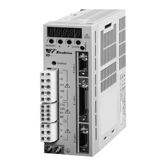
XD-@, XD-@-E
XtraDrive
Intelligent servo drive. Integrated controller
and network connectivity.
• NCT. Patented non-linear algorithm for tight control
• Very low tracking error with no overshoot and zero
settling time
• Supports different servo motor encoder types
• PROFIBUS embedded in the drive available
• XtraDive model available with electronic CAM
• The ideal drive for linear motor control
• Fast hardware registration input
• Intuitive text programming language
• Automatic tuning of servo parameters for optimal
settling time
• Oscilloscope available via XtraWare software tool
• CompoWay/F is supported, it allows remote access
to the drives through the PLC
Ratings
• 230 VAC single-phase 30 W to 1.5 kW (4.77 Nm)
• 400 VAC three-phase 0.5 kW to 5.0 kW (28.4 Nm)
System configuration
XtraDrive
Servo Drives
Filter
PROFIBUS network
(XtraDrive models with
embedded PROFIBUS)
(Refer to chapter
SmartStep servo motors)
Cables
R7M Servo Motor
XtraDrive
CN3
CHARGE
CN1
CN2
(Refer to chapter
Sigma-II rotary motors)
Cables
SGMAH, SGMPH
SGMGH, SGMUH,
Servo Motor
SGMSH, SGMBH
Servo Motor
Analog monitor cable
Human machine interface
Personal computer
Motion control unit
General purpose cable
Terminal block
(Refer to chapter Sigma-II linear motors)
SGLG_ linear
Servo Motor
NS115
S
W
1
Option unit
A
R
S
W
2
C
N
6
A
C
N
6
B
C
N
4
Position control
unit
Cables
SGLF_ linear
SGLT_ linear
Servo Motor
Servo Motor
121
Advertisement
Table of Contents

Related Manuals for Omron XTRADRIVE


Summary of Contents for Omron XTRADRIVE
-
Page 1: System Configuration
• CompoWay/F is supported, it allows remote access to the drives through the PLC Ratings • 230 VAC single-phase 30 W to 1.5 kW (4.77 Nm) • 400 VAC three-phase 0.5 kW to 5.0 kW (28.4 Nm) System configuration Analog monitor cable... - Page 2 Capacity 230 V (1-phase) 230 V (1-phase) 400 V (3-phase) 400 V (3-phase) w PROFIBUS w PROFIBUS Sigma-II series motors (refer to the Sigma-II rotary motors chapter for details) SGMAH (3000 min 230 V 0.0955 N.m 30 W XD-P3-MN01-@ XD-P3-MSD0-@ 0.159 N.m...
-
Page 3: Type Designation
Max. output current Arms 40.5 Input power Main circuit For three-phase, 380 to 480 VAC + 10 to -15% (50/60 Hz) Supply Control circuit 24 VDC+15% Control method Three phase full-wave rectification / IGBT / PWM / sine-wave current drive method... -
Page 4: General Specifications
Rotation direction selection With P control signal speed Speed selection With forward/reverse current limit signal (speed 1 to 3 selection), servo motor stops or another control method is reference used when both are OFF. Bias Setting 0 to 450 min... - Page 5 (+12 V power supply is built into the SERVOPACK). Note: 1. Pin numbers in parentheses () indicate signal grounds. 2. The functions allocated to /S-ON, /P-CON. P-OT, N-OT, /ALM-RST, /P-CL, and /N-CL input signals can be changed by using the parameters.
- Page 6 Do not connect relays to these terminals. Note: 1. Pin numbers in parentheses () indicate signal grounds. 2. The functions allocated to /TGON, /S-RDY, and /V-CMP (/COIN) can be changed by using the parameters. /CLT, /VLT, /BK, /WARN, and /NEAR signals can also be changed.
- Page 7 Dimensions Servo drives XD-P3-M@ to XD-02-M@ (230V, 30 to 200W) CN10 Terminal CHARGE block Ground terminal 2 M4 screws XD-04-M@ (230V, 400W) 5 holes CN10 Terminal block CHARGE Ground terminal 2 M4 screws XD-08-M@ (230V, 750W) 96.2 5 hole CN10...
- Page 8 XD-05-T@ to -15-T@ (400V, 0.5 to 1.5kW) 5 holes Heat sink CN10 CHARGE Terminal Ground block terminal 100 0.5 2 M4 screws XD-15-M@ (230V, 1.5kW) XD-20-T@, XD-30-T@ (400V, 2/3kW) 6 holes Heat sink CN10 CHARGE POWER 14-pin terminal M4 mounting screw 100 0.5...
- Page 9 Filters R88A-FIW104-SE R88A-FIW4006-SE, R88A-FIW4010-SE Units:mm (in) Model R88A-FIW4006-SE R88A-FIW4010-SE Dimensions 32 (1.26) 35 (1.38) in mm (in) 16 (0.63) 18 (0.71) 202(7.95) 202 (7.95) 291 (11.46) 192(7.56) 28.25(1.11) 149.5(5.89) 192 (7.56) 281 (11.06) 150 (5.91) 239 (9.41) 300 (11.81) 270 (10.63) M4(2 ) 70 (2.76)
-
Page 10: Installation
Max. operating current: connector shell. 50 mA DC *1 The time constant for the primary filter is 47 µs. *2 Connect when using an absolute encoder. *3 Used only with an absolute encoder. *4 Regenerative resistor can be connected between B1 and B2. - Page 11 *2 Connect when using an absolute encoder. *3 Used only with an absolute encoder. *4 For using an external regenerative resistor, connect it between B1 and B2. *5 The 24VDC power is supplyed by the user. *6 TI stands for Texas Instruments Inc.
-
Page 12: Ordering Information
XD-30-TSD0 XD-30-TSD0-E SGMGH-30D@, SGLFW-1ZD380@, SGMSH/UH-30D@ SGLFW-1ED560@, SGLTW-40D400@ 5.0 kW XD-50-TN XD-50-TN00-E SGMGH-44D@, SGLTW-40D600@, SGMSH/UH-40D@, SGLTW-80D400@ SGMSH-50D@ Note: SGLGW-@ linear motor combination is made considering the use of standard magnets. Refer to the linear motors chapter for details AC servo systems... - Page 13 (for 400 V motors SGMGH-(20/30/44)D@, Relay terminal General purpose 1 m R88A-CTW001N SGMSH-(30/40/50)D@, SGMUH-(30/40)D@) block cable controller 2 m R88A-CTW002N Military brake connector IP67 (for 400 V servo motors MS3108E10SL-3S Relay terminal XW2B-50G5 SGMGH-@, SGMSH-@, SGMUH-@) block Computer software Cable (for CN5)
- Page 14 ALL DIMENSIONS SHOWN ARE IN MILLIMETERS. To convert millimeters into inches, multiply by 0.03937. To convert grams into ounces, multiply by 0.03527. In the interest of product improvement, specifications are subject to change without notice. Cat. No. I18E-EN-02 AC servo systems...
Need help?
Do you have a question about the XTRADRIVE and is the answer not in the manual?
Questions and answers