Omron NX-series User Manual
Hide thumbs
Also See for NX-series:
- User manual (464 pages) ,
- Hardware user manual (222 pages) ,
- Reference manual (116 pages)

Related Manuals for Omron NX-series


Summary of Contents for Omron NX-series
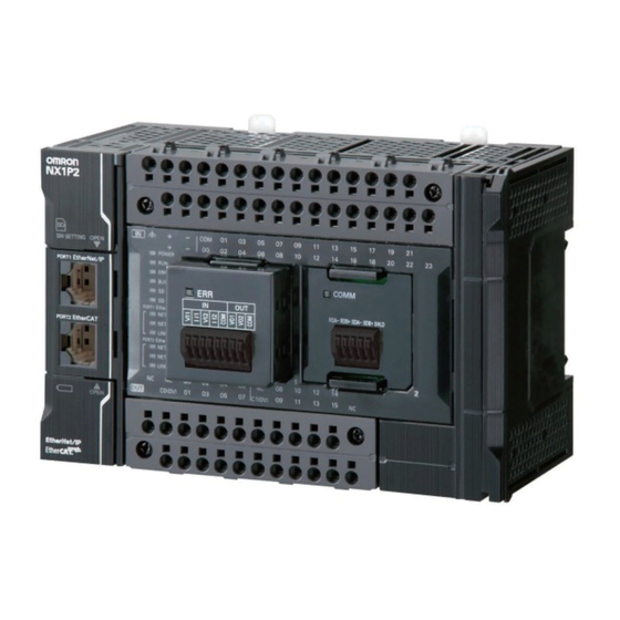
- Page 1 Machine Automation Controller NX-series NX1P2 CPU Unit Built-in I/O and Option Board User’s Manual NX1P2-11 NX1P2-111 NX1P2-10 NX1P2-101 NX1P2-90 NX1P2-901 CPU Unit W579-E1-04...
- Page 2 No patent liability is assumed with respect to the use of the information contained herein. Moreover, because OMRON is constantly striving to improve its high-quality products, the information contained in this manual is subject to change without notice. Every precaution has been taken in the preparation of this manual. Neverthe- less, OMRON assumes no responsibility for errors or omissions.
-
Page 3: Introduction
Thank you for purchasing an NX-series NX1P2 CPU Unit. This manual contains information that is necessary to use the NX-series NX1P2 CPU Unit. Please read this manual and make sure you understand the functionality and performance of the NX-series NX1P2 CPU Unit before you attempt to use it in a control system. -
Page 4: Table Of Contents
Procedure Details........................1-8 Section 2 Built-in I/O Built-in I/O Terminal Allocation .................... 2-2 2-1-1 Terminal Arrangement ......................... 2-2 I/O Data Specifications......................2-5 2-2-1 NX1P2-24DT/-24DT1 ..................... 2-5 2-2-2 NX1P2-40DT/-40DT1 ..................... 2-6 NX-series NX1P2 CPU Unit Built-in I/O and Option Board User’s Manual (W579) -
Page 5: Contents
Connection with General-purpose Serial Communications Devices ......4-25 4-5-1 Overview........................... 4-25 4-5-2 Procedure ..........................4-26 4-5-3 Settings............................. 4-28 4-5-4 Programming ..........................4-29 Section 5 Analog I/O Specifications ........................5-2 5-1-1 Analog I/O Option Boards......................5-2 NX-series NX1P2 CPU Unit Built-in I/O and Option Board User’s Manual (W579) - Page 6 Linear Interpolation ........................6-57 6-6-3 Circular Interpolation ......................... 6-58 6-6-4 Axes Group Cyclic Synchronous Positioning ................6-58 6-6-5 Stopping Under Multi-axes Coordinated Control............... 6-59 6-6-6 Overrides for Multi-axes Coordinated Control................6-61 NX-series NX1P2 CPU Unit Built-in I/O and Option Board User’s Manual (W579)
- Page 7 Overview of Troubleshooting ....................9-2 Option Board Errors......................9-3 9-2-1 Checking for Errors and Troubleshooting with the ERR Indicator on Option Boards ....9-3 Appendices A-1 Version Information.......................A-2 Index NX-series NX1P2 CPU Unit Built-in I/O and Option Board User’s Manual (W579)
- Page 8 CONTENTS NX-series NX1P2 CPU Unit Built-in I/O and Option Board User’s Manual (W579)
-
Page 9: Relevant Manuals
Using motion control Using EtherCAT Using EtherNet/IP *1. Refer to the NJ/NX-series Troubleshooting Manual (Cat. No. W503) for the error management concepts and the error items. NX-series NX1P2 CPU Unit Built-in I/O and Option Board User’s Manual (W579) -
Page 10: Manual Structure
Manual name NJ-series CPU Unit Hardware User’s Manual (W500) Note This illustration is provided only as a sample. It may not literally appear in this manual. NX-series NX1P2 CPU Unit Built-in I/O and Option Board User’s Manual (W579) -
Page 11: Special Information
Sysmac Studio on the computer with the data in the physical Controller and transfer the data in the direction that is specified by the user. NX-series NX1P2 CPU Unit Built-in I/O and Option Board User’s Manual (W579) -
Page 12: Terms And Conditions Agreement
Omron’s exclusive warranty is that the Products will be free from defects in materials and workman- ship for a period of twelve months from the date of sale by Omron (or such other period expressed in writing by Omron). Omron disclaims all other warranties, express or implied. -
Page 13: Application Considerations
Disclaimers Performance Data Data presented in Omron Company websites, catalogs and other materials is provided as a guide for the user in determining suitability and does not constitute a warranty. It may represent the result of Omron’s test conditions, and the user must correlate it to actual application requirements. Actual perfor- mance is subject to the Omron’s Warranty and Limitations of Liability. -
Page 14: Safety Precautions
Safety Precautions Safety Precautions Refer to the following manuals for safety precautions. • NX-series NX1P2 CPU Unit Hardware User’s Manual (Cat. No. W578) NX-series NX1P2 CPU Unit Built-in I/O and Option Board User’s Manual (W579) -
Page 15: Precautions For Safe Use
Precautions for Safe Use Precautions for Safe Use Refer to the following manuals for precautions for safe use. • NX-series NX1P2 CPU Unit Hardware User’s Manual (Cat. No. W578) NX-series NX1P2 CPU Unit Built-in I/O and Option Board User’s Manual (W579) -
Page 16: Precautions For Correct Use
Precautions for Correct Use Precautions for Correct Use Refer to the following manuals for precautions for correct use. • NX-series NX1P2 CPU Unit Hardware User’s Manual (Cat. No. W578) NX-series NX1P2 CPU Unit Built-in I/O and Option Board User’s Manual (W579) -
Page 17: Regulations And Standards
Regulations and Standards Regulations and Standards Refer to the following manuals for regulations and standards. • NX-series NX1P2 CPU Unit Hardware User’s Manual (Cat. No. W578) NX-series NX1P2 CPU Unit Built-in I/O and Option Board User’s Manual (W579) -
Page 18: Versions
Versions Versions Hardware revisions and unit versions are used to manage the hardware and software in NX-series Units and EtherCAT slaves. The hardware revision or unit version is updated each time there is a change in hardware or software specifications. Even when two Units or EtherCAT slaves have the same model number, they will have functional or performance differences if they have different hardware revisions or unit versions. - Page 19 Click the Show Detail or Show Outline Button at the lower right of the Production Information Dialog Box. The view will change between the production information details and outline. Outline View Detail View NX-series NX1P2 CPU Unit Built-in I/O and Option Board User’s Manual (W579)
-
Page 20: Unit Versions Of Cpu Units And Sysmac Studio Versions
Unit Versions of CPU Units and Sysmac Studio Versions The functions that are supported depend on the unit version of the NX-series CPU Unit. The version of Sysmac Studio that supports the functions that were added for an upgrade is also required to use those functions. -
Page 21: Related Manuals
CPU Unit Motion Con- motion control set- Unit and programming concepts for NX1P2- trol User’s Manual tings and program- motion control are described. NJ501- ming concepts. NJ301- NJ101- NX-series NX1P2 CPU Unit Built-in I/O and Option Board User’s Manual (W579) - Page 22 NX Unit data that is required to config- required to configure systems with ure systems with NX-series Units are provided. NX-series Units NX-series NX1P2 CPU Unit Built-in I/O and Option Board User’s Manual (W579)
- Page 23 Provides an overview of the communi- Temperature Controllers communications cations method, communications Communications functions of E5C specifications, and wiring of E5C Manual Digital Tempera- Digital Temperature Controllers. ture Controllers NX-series NX1P2 CPU Unit Built-in I/O and Option Board User’s Manual (W579)
- Page 24 Application Description E5C Digital H174 E5C Learning about the Describes how to use E5C Digital Temperature Controllers functions of E5C Temperature Controllers. User’s Manual Digital Tempera- ture Controllers NX-series NX1P2 CPU Unit Built-in I/O and Option Board User’s Manual (W579)
-
Page 25: Terminology
Controller event. Controller information Information that is defined by the NJ/NX-series System that is not an error. It rep- resents an information Controller event. NX-series NX1P2 CPU Unit Built-in I/O and Option Board User’s Manual (W579) - Page 26 One of the event levels for Controller events or user-defined events. These are not errors, but appear in the event log to notify the user of specific information. NX-series NX1P2 CPU Unit Built-in I/O and Option Board User’s Manual (W579)
- Page 27 ST programming that is included within a ladder diagram program. instruction The smallest unit of the processing elements that are provided by OMRON for use in POU algorithms. There are ladder diagram instructions (program inputs and out- puts), function instructions, function block instructions, and ST statements.
- Page 28 One type of EtherCAT communications in which service data objects (SDOs) are used to transmit information whenever required. Servo Drive/encoder input slave Any of the EtherCAT slaves that is assigned to an axis. In the NJ/NX-series Sys- tem, it would be a Servo Drive or Encoder Input Slave Unit. slave A device that performs remote I/O for a master.
- Page 29 All of the programs in one project. user-defined event One of the events in the NJ/NX-series System. These events are defined by the user. “User-defined events” is a generic term for user-defined errors and user-defined information. user-defined variable A variable for which all of the attributes are defined by the user and can be changed by the user.
-
Page 30: Revision History
January 2017 Corrected mistakes. October 2017 Added shipbuilding standards (LR). January 2019 Made changes accompanying the transfer of explanation for event codes and errors to the NJ/NX-series Troubleshooting Manual. NX-series NX1P2 CPU Unit Built-in I/O and Option Board User’s Manual (W579) -
Page 31: Sections In This Manual
Appendices CPU Units Built-in I/O Index Option Boards Serial Communications Analog I/O Introduction of Motion Control Functions Introduction of EtherNet/IP Communications Functions Introduction of EtherCAT Communications Functions Troubleshooting NX-series NX1P2 CPU Unit Built-in I/O and Option Board User’s Manual (W579) - Page 32 Sections in this Manual NX-series NX1P2 CPU Unit Built-in I/O and Option Board User’s Manual (W579)
-
Page 33: Introduction To Nx1P2 Cpu Units
Procedure Details ..........1-8 1 - 1 NX-series NX1P2 CPU Unit Built-in I/O and Option Board User’s Manual (W579) -
Page 34: Function Specifications For Nx1P2 Cpu Units
0 to 1,536 words (H0 to H1,535) specified with DM Area AT specifica- 0 to 16,000 words (D0 to D15,999) tions for vari- EM Area ables.) 1 - 2 NX-series NX1P2 CPU Unit Built-in I/O and Option Board User’s Manual (W579) - Page 35 Maximum number of cam tables 80 tables Position units Pulse, mm, μm, nm, degree, and inch Override Factors 0.00% or 0.01% to 500.00% 1 - 3 NX-series NX1P2 CPU Unit Built-in I/O and Option Board User’s Manual (W579)
- Page 36 UCMM Explicit mes- (non-connec- Maximum num- sages tion type) ber of servers that can commu- nicate at one time Number of TCP sockets 1 - 4 NX-series NX1P2 CPU Unit Built-in I/O and Option Board User’s Manual (W579)
- Page 37 At ambient temperature of 0°C: -3 to 1 min error per month Retention time of built-in capacitor At ambient temperature of 40°C: 10 days 1 - 5 NX-series NX1P2 CPU Unit Built-in I/O and Option Board User’s Manual (W579)
- Page 38 *4. The value can be set in 1-word increments. The value is included in the total size of variables with Retain attributes. *5. For details on each axis, refer to the NJ/NX-series CPU Unit Motion Control User’s Manual (Cat. No. W507).
-
Page 39: Overall Operating Procedure
Actual System Connect the Support Software to the physical system and download the project. Check operation on the physical system and then start actual system operation. 1 - 7 NX-series NX1P2 CPU Unit Built-in I/O and Option Board User’s Manual (W579) -
Page 40: Procedure Details
NX-series EtherCAT Coupler Slave Terminal Tab described in step 5.) Units User’s Manual (Cat. Page 2. Setting up any Slave Terminals that No. W519) are used. 1 - 8 NX-series NX1P2 CPU Unit Built-in I/O and Option Board User’s Manual (W579) - Page 41 Setting the initial values for an Configurations and 3-2-1 Settings on page 3-4 Option Board Setup − Controller Setup − Option Board Settings Step 2-3 Programming 1 - 9 NX-series NX1P2 CPU Unit Built-in I/O and Option Board User’s Manual (W579)
- Page 42 Built-in EtherCAT Port User’s • Connecting the built-in EtherNet/IP port Manual (Cat. No. W505) NJ/NX-series CPU Unit Built-in EtherNet/IP Port User’s Manual (Cat. No. W506) 1 - 10 NX-series NX1P2 CPU Unit Built-in I/O and Option Board User’s Manual (W579)
- Page 43 3. Actual Controller Start actual operation. Operation *1. Use the Synchronize Menu of the Sysmac Studio to download the project. 1 - 11 NX-series NX1P2 CPU Unit Built-in I/O and Option Board User’s Manual (W579)
- Page 44 1 Introduction to NX1P2 CPU Units 1 - 12 NX-series NX1P2 CPU Unit Built-in I/O and Option Board User’s Manual (W579)
-
Page 45: Built-In I/O
I/O Response Time of Built-in I/O ....... . . 2-15 2 - 1 NX-series NX1P2 CPU Unit Built-in I/O and Option Board User’s Manual (W579) -
Page 46: Built-In I/O Terminal Allocation
The arrangement of these terminals is shown below. NX1P2-24DT/-24DT1 POWER Input terminal block Output terminal block NX1P2- 24DT LINK/ACT NC NC C0 (0V) NX1P2- 24DT1 LINK/ACT NC C0 (+V) 2 - 2 NX-series NX1P2 CPU Unit Built-in I/O and Option Board User’s Manual (W579) - Page 47 2 Built-in I/O Input Terminal Block Output Terminal Block NX1P2-24DT C0 (0V) NX1P2-24DT1 C0 (+V) 2 - 3 NX-series NX1P2 CPU Unit Built-in I/O and Option Board User’s Manual (W579)
- Page 48 40DT1 LINK/ACT NC C0 (+V) C1 (+V) Input Terminal Block Output Terminal Block NX1P2-40DT C0 (0V) C1 (0V) NX1P2-40DT1 C0 (+V) C1 (+V) 2 - 4 NX-series NX1P2 CPU Unit Built-in I/O and Option Board User’s Manual (W579)
-
Page 49: I/O Data Specifications
I/O ports are generated automatically by the Sysmac Studio. To use I/O data in the user program, you use device variables assigned to the relevant I/O ports. Refer to the NJ/NX-series CPU Unit Software User’s Manual (Cat. No. W501) for I/O ports and device variables. -
Page 50: Nx1P2-40Dt/-40Dt1
The output set value for output bit 14. BOOL Output Bit 14 Output Bit 15 The output set value for output bit 15. BOOL Output Bit 15 2 - 6 NX-series NX1P2 CPU Unit Built-in I/O and Option Board User’s Manual (W579) -
Page 51: Built-In I/O Functions
2-5-2 Output Load Rejec- ting watchdog timer error or an error in the major fault level tion Setting on page 2-12 occurs in the CPU Unit. 2 - 7 NX-series NX1P2 CPU Unit Built-in I/O and Option Board User’s Manual (W579) -
Page 52: Settings
Load Rejec- Set the output at load Turn OFF Turn OFF When downloaded tion Output rejection. to CPU Unit allowed. Hold the present Settings value 2 - 8 NX-series NX1P2 CPU Unit Built-in I/O and Option Board User’s Manual (W579) -
Page 53: I/O Map
Select Configurations and Setup - I/O Map to display the I/O Map. Refer to the Sysmac Studio Version 1 Operation Manual (Cat. No. W504) for how to register device variables with the Sysmac Studio. 2 - 9 NX-series NX1P2 CPU Unit Built-in I/O and Option Board User’s Manual (W579) -
Page 54: Functions
Input value is ON because all inputs because all inputs are not ON during are ON during four times of reading. four times of reading. Input value 2 - 10 NX-series NX1P2 CPU Unit Built-in I/O and Option Board User’s Manual (W579) - Page 55 Unit or signal lines and noise source, or protect the Unit or signal lines. 2 - 11 NX-series NX1P2 CPU Unit Built-in I/O and Option Board User’s Manual (W579)
-
Page 56: Output Load Rejection Setting
Configure the settings in the Built-in I/O Settings Tab Page, which is displayed by selecting Built-in I/O Settings under Configurations and Setup - Controller Setup. Each setting corresponds to 1 output. 2 - 12 NX-series NX1P2 CPU Unit Built-in I/O and Option Board User’s Manual (W579) -
Page 57: I/O Refreshing
Input ON/OFF response time + Input filter time Input values: Read input values: Input device variables: Output device variables: Refresh outputs: Output ON/OFF response time Output terminal status: 2 - 13 NX-series NX1P2 CPU Unit Built-in I/O and Option Board User’s Manual (W579) - Page 58 Some NX Units connected to a CPU Unit or EtherCAT Slave Terminal and Units other than NX Units support synchronous I/O refreshing. Refer to the NJ/NX-series CPU Unit Software User’s Manual (Cat. No. W501) or the NX-series EtherCAT Coupler Unit User’s Manual (Cat. No. W519) for synchronous I/O refreshing.
-
Page 59: I/O Response Time Of Built-In I/O
Input ON/OFF response time + Input filter time Input values: Read input values: Input device variables: Output device variables: Refresh outputs: Output ON/OFF response time Output terminal status: Minimum I/O response time 2 - 15 NX-series NX1P2 CPU Unit Built-in I/O and Option Board User’s Manual (W579) - Page 60 The input ON/OFF response time and the output ON/OFF response time vary depending on the terminal that is used. Refer to the NX-series NX1P2 CPU Unit Hardware User’s Manual (Cat. No. W578) for the specifications of each terminal. 2 - 16...
- Page 61 How Option Boards Operate in Case of an Error ..... 3-14 3 - 1 NX-series NX1P2 CPU Unit Built-in I/O and Option Board User’s Manual (W579)
-
Page 62: Option Board Types
Option Board COMM COMM RDA- RDB+ SDA- SDB+ SHLD SG0 RD SD ER SG1 DR RS CS SHLD Serial Communications Analog I/O Option Board Option Board 3 - 2 NX-series NX1P2 CPU Unit Built-in I/O and Option Board User’s Manual (W579) -
Page 63: Serial Communications Option Boards
6 ms/Option Board Isolation No-isolation No-isolation No-isolation External connection termi- Screwless clamping termi- Screwless clamping termi- Screwless clamping termi- nal block nal block nal block 3 - 3 NX-series NX1P2 CPU Unit Built-in I/O and Option Board User’s Manual (W579) -
Page 64: Using Option Boards
I/O Map will also be deleted. After you change the Option Board configuration, you need to map the device variables again. 3 - 4 NX-series NX1P2 CPU Unit Built-in I/O and Option Board User’s Manual (W579) - Page 65 Settings/Option Board 2 Serial Communications Settings in the Option Board Settings Tab Page, which is displayed by selecting Option Board Settings under Configurations and Setup - Controller Setup. 3 - 5 NX-series NX1P2 CPU Unit Built-in I/O and Option Board User’s Manual (W579)
- Page 66 Therefore, in order to use the host link (FINS) protocol, you need to generate memory used for CJ-series Units in the NX1P2 CPU Unit. The memory settings for CJ-series Units are used for this purpose. 3 - 6 NX-series NX1P2 CPU Unit Built-in I/O and Option Board User’s Manual (W579)
- Page 67 Specify the memory used for CJ-series Units in the Memory Settings for CJ-series Units Tab Page, which is displayed by selecting Memory Settings under Configurations and Setup - Controller Setup. 3 - 7 NX-series NX1P2 CPU Unit Built-in I/O and Option Board User’s Manual (W579)
- Page 68 Words) CPU Unit Refer to the NJ/NX-series CPU Unit Software User’s Manual (Cat. No. W501) for the specifications of memory used for CJ-series Units. 3 - 8 NX-series NX1P2 CPU Unit Built-in I/O and Option Board User’s Manual (W579)
-
Page 69: System-Defined Variables
3-2-2 System-defined Variables The following table shows the system-defined variables available for Option Boards. Refer to the NJ/NX-series CPU Unit Software User’s Manual (Cat. No. W501) for details on the specifi- cations of system-defined variables for Option Boards. Variable Meaning... -
Page 70: Device Variables
Specify device variables in the I/O Map Tab Page, which is displayed by selecting Configurations and Setup - I/O Map. The following is an example of Option Board displayed on the I/O Map Tab Page. 3 - 10 NX-series NX1P2 CPU Unit Built-in I/O and Option Board User’s Manual (W579) -
Page 71: Assigning Device Variables To Option Boards
Right-click Node location information and select Create Device Variable from the menu. The variable name is written to the Variable Field of the Node location information port. 3 - 11 NX-series NX1P2 CPU Unit Built-in I/O and Option Board User’s Manual (W579) - Page 72 _PLC_OptBoardSta[].Run _gOptBoard_ID1 Device variable to analog input 1 on Option Board 1 OP1_Ch1_Analog_Input_Value Input value to analog input 1 read into the CPU Unit OP1_Ch1_Analog_Input_Value_Valid 3 - 12 NX-series NX1P2 CPU Unit Built-in I/O and Option Board User’s Manual (W579)
-
Page 73: Instructions Used For Option Boards
NX_SerialBufClear Clear Buffer Clears the send or receive buffer. Refer to the NJ/NX-series Instructions Reference Manual (Cat. No. W502-E1-17 or later) for details on serial communications instructions. 3 - 13 NX-series NX1P2 CPU Unit Built-in I/O and Option Board User’s Manual (W579) -
Page 74: How Option Boards Operate In Case Of An Error
Analog input value reset to 0. Mounted communications instruction when Host Option Board Error Link (FINS) is not selected. Analog Option Board Startup Error Analog Option Board Communi- cations Error 3 - 14 NX-series NX1P2 CPU Unit Built-in I/O and Option Board User’s Manual (W579) -
Page 75: Serial Communications
Programming ..........4-29 4 - 1 NX-series NX1P2 CPU Unit Built-in I/O and Option Board User’s Manual (W579) -
Page 76: Serial Communications Types And Overview
In this data exchange, you use spe- RS-232C Option Board or cial instructions to send a Mod- RS-422A/485 Option Board bus-RTU command and receive a response. RS-232C or RS-422A/485 Inverter 4 - 2 NX-series NX1P2 CPU Unit Built-in I/O and Option Board User’s Manual (W579) - Page 77 *2. Only FINS commands are supported. C-mode commands are not supported. *3. The function to use NX1P2 CPU Units as Modbus-RTU slaves is not supported. 4 - 3 NX-series NX1P2 CPU Unit Built-in I/O and Option Board User’s Manual (W579)
-
Page 78: Programless Communications With Nb-Series Programmable Terminals
Determining the usable memory Programming Creating screen data Mounting and setting hardware Wiring and power ON Downloading the project Transferring screen data Checking operation and actual operation 4 - 4 NX-series NX1P2 CPU Unit Built-in I/O and Option Board User’s Manual (W579) - Page 79 In the NB-Designer, download the proj- data ect that contains the screen data. Checking operation Check the operation of the user program and actual operation and screen data. 4 - 5 NX-series NX1P2 CPU Unit Built-in I/O and Option Board User’s Manual (W579)
-
Page 80: Settings
Precautions for Correct Use Create screen data to avoid using the EM area because the NX1P2 CPU Unit does not support the EM area type. 4 - 6 NX-series NX1P2 CPU Unit Built-in I/O and Option Board User’s Manual (W579) - Page 81 Refer to the NB-series Programmable Terminals NB-Designer Operation Manual (Cat. No. V106) for the detailed settings. Refer to 4-2-5 Connection Examples on page 4-9 for information on wiring the serial port. 4 - 7 NX-series NX1P2 CPU Unit Built-in I/O and Option Board User’s Manual (W579)
-
Page 82: Programming
CJ-series Units that will be accessed by the NB-series Unit by using AT specification. Then, create the user program for communicating with the NB-series Unit. Refer to the NJ/NX-series CPU Unit Software User’s Manual (Cat. No. W501) for memory used for CJ-series Units and AT specification. -
Page 83: Connection Examples
Refer to the NB-series Programmable Terminals Setup Manual (Cat. No. V107) for wiring information on connecting the CPU Unit to the serial ports on an NB5Q/NB7W/NB10W Programmable Terminal. 4 - 9 NX-series NX1P2 CPU Unit Built-in I/O and Option Board User’s Manual (W579) -
Page 84: Programless Communications With E5C Digital Temperature Controllers
Refer to the E5 C Digital Temperature Controllers Use’s Manual (Cat. No. H174) for the pro- gramless communications of E5C Controllers. 4 - 10 NX-series NX1P2 CPU Unit Built-in I/O and Option Board User’s Manual (W579) - Page 85 C Digital Temperature Controllers User’s Manual (Cat. No. H174) and the E5 C Digi- tal Temperature Controllers Communications Manual (Cat. No. H175) for details on the specifications of E5C Controllers. 4 - 11 NX-series NX1P2 CPU Unit Built-in I/O and Option Board User’s Manual (W579)
-
Page 86: Procedure
In the Sysmac Studio, create a program 4-3-4 Programming on page 4-17 to access the memory used for CJ-series Units by using user-defined variables with AT specifications. 4 - 12 NX-series NX1P2 CPU Unit Built-in I/O and Option Board User’s Manual (W579) - Page 87 E5C Controller is sent too soon. When a receiving of the command frame failed, increase the send data wait time of the E5C Controller. 4 - 13 NX-series NX1P2 CPU Unit Built-in I/O and Option Board User’s Manual (W579)
-
Page 88: Settings
Determine and set the area type and the number of words based on the first address of the E5C Controller and the number of Controllers to connect. 4 - 14 NX-series NX1P2 CPU Unit Built-in I/O and Option Board User’s Manual (W579) - Page 89 (Not used) With RS control for receive data With RS control for send data *1. Turn this OFF if the NX1W-CIF11/CIF12 is not the terminating device. 4 - 15 NX-series NX1P2 CPU Unit Built-in I/O and Option Board User’s Manual (W579)
- Page 90 Refer to the E5 C Digital Temperature Controllers Communications Manual (Cat. No. H175) for details on the parameters used for programless communications of E5C Controllers. 4 - 16 NX-series NX1P2 CPU Unit Built-in I/O and Option Board User’s Manual (W579)
-
Page 91: Programming
The user program gets the E5C Controller status from the upload area of the E5C Controller and sends commands to the download area of the E5C Controller. Refer to the NJ/NX-series CPU Unit Software User’s Manual (Cat. No. W501) for memory used for CJ-series Units and AT specification. -
Page 92: Connection With Modbus-Rtu Slaves
Modbus-RTU command and receive a response. Therefore, you can easily create a program to exchange data with Modbus-RTU slaves. Refer to the NJ/NX-series Instructions Reference Manual (Cat. No. W502-E1-17 or later) for the speci- fication of instructions. -
Page 93: Procedure
User’s Manual (Cat. No. W501) Checking operation Check the operation of the user program Sysmac Studio Version 1 Operation and actual operation and Modbus-RTU slaves. Manual (Cat. No. W504) 4 - 19 NX-series NX1P2 CPU Unit Built-in I/O and Option Board User’s Manual (W579) - Page 94 • Adjustment on the Modbus-RTU Slave side Increase the wait time from when the Modbus-RTU slave receives a command until it sends a response. 4 - 20 NX-series NX1P2 CPU Unit Built-in I/O and Option Board User’s Manual (W579)
-
Page 95: Settings
Set the same baud rate as for the NX1P2 CPU Unit. Set the MODBUS slave address. Configure the functions of Modbus-RTU slaves as required. Refer to the manual for the Modbus-RTU slave to connect. 4 - 21 NX-series NX1P2 CPU Unit Built-in I/O and Option Board User’s Manual (W579) -
Page 96: Programming
Command Option Board to Modbus-RTU slaves using Modbus-RTU protocol. Refer to the NJ/NX-series Instructions Reference Manual (Cat. No. W502-E1-17 or later) for details on these instructions. 4 - 22 NX-series NX1P2 CPU Unit Built-in I/O and Option Board User’s Manual (W579) - Page 97 Option Board Normal Operation of Option Board 1 Status system-defined variable _PLC_OptBoardSta[1].Run Refer to the NJ/NX-series CPU Unit Software User’s Manual (Cat. No. W501) for the specifications of the _PLC_OptBoardSta (Option Board Status) system-defined variable. 4 - 23 NX-series NX1P2 CPU Unit Built-in I/O and Option Board User’s Manual (W579)
-
Page 98: Connection Examples
4 Serial Communications 4-4-5 Connection Examples An example of connecting an OMRON 3G3MX2-V1 Inverter via RS-422A/485 is given below. Serial Communications Terminals RS-422A/485 Option Board 3G3MX2-V1 Inverter NX1W-CIF11/CIF12 RDA- RDB+ SDA- SDB+ SHLD Operation Setting DIP Switches on the Back of the NX1W-CIF11/CIF12 Option... -
Page 99: Connection With General-Purpose Serial Communications Devices
The instruction to receive data in No-Protocol mode refers to an instruction that reads data received at the specified port into the specified variable without converting it. Refer to the NJ/NX-series Instructions Reference Manual (Cat. No. W502-E1-17 or later) for the speci- fication of instructions. -
Page 100: Procedure
Connect the serial communications ter- minals of the Option Boards and gen- eral-purpose serial communications devices. Wire the power supply terminals and turn ON the power supply. 4 - 26 NX-series NX1P2 CPU Unit Built-in I/O and Option Board User’s Manual (W579) - Page 101 • Adjustment on the general-purpose serial communications device side Increase the wait time from when the general-purpose serial communications device receives the data until it sends the data. 4 - 27 NX-series NX1P2 CPU Unit Built-in I/O and Option Board User’s Manual (W579)
-
Page 102: Settings
Configure the serial communications settings to match those of the NX1P2 CPU Unit. Refer to the manual for the general-purpose serial communications device to connect. 4 - 28 NX-series NX1P2 CPU Unit Built-in I/O and Option Board User’s Manual (W579) -
Page 103: Programming
NX_SerialBufClear Clear Buffer Clears the send or receive buffer. Refer to the NJ/NX-series Instructions Reference Manual (Cat. No. W502-E1-17 or later) for details on these instructions. 4 - 29 NX-series NX1P2 CPU Unit Built-in I/O and Option Board User’s Manual (W579) - Page 104 Variable that specifies target port Variable assigned to Option Board OptionBoard1_location_information Refer to 3-2-4 Assigning Device Variables to Option Boards on page 3-11 for assigning variables to Option Boards. 4 - 30 NX-series NX1P2 CPU Unit Built-in I/O and Option Board User’s Manual (W579)
- Page 105 _PLC_OptBoardSta[1].Run Option Board Normal Operation of Option Board 1 Status system-defined variable Refer to the NJ/NX-series CPU Unit Software User’s Manual (Cat. No. W501) for the specifications of the _PLC_OptBoardSta (Option Board Status) system-defined variable. 4 - 31 NX-series NX1P2 CPU Unit Built-in I/O and Option Board User’s Manual (W579)
- Page 106 4 Serial Communications 4 - 32 NX-series NX1P2 CPU Unit Built-in I/O and Option Board User’s Manual (W579)
-
Page 107: Analog I/O
Response Time ..........5-13 5 - 1 NX-series NX1P2 CPU Unit Built-in I/O and Option Board User’s Manual (W579) -
Page 108: Specifications
Displays the operating status of the Analog I/O Option Board. Terminal block The terminal block for wiring the analog input and analog output ter- minals. 5 - 2 NX-series NX1P2 CPU Unit Built-in I/O and Option Board User’s Manual (W579) -
Page 109: Terminal Arrangement
The following table shows the terminal arrangement of Analog I/O Option Boards. ADB21 DAB21V MAB221 Refer to the NX-series NX1P2 CPU Unit Hardware User’s Manual (Cat. No. W578) for information on wiring Analog I/O Option Boards. 5-1-4 Input Range and Output Range... - Page 110 Output set value (Decimal) 4,000 4,095 32,767 In the output mode at load rejection, the value when the output set value is 0 is output. 5 - 4 NX-series NX1P2 CPU Unit Built-in I/O and Option Board User’s Manual (W579)
-
Page 111: Procedure
Check the wiring. Sysmac Studio Version 1 Operation and actual operation Manual (Cat. No. W504) Check the operation of the user program and screen data. 5 - 5 NX-series NX1P2 CPU Unit Built-in I/O and Option Board User’s Manual (W579) -
Page 112: Settings
When you use the current input range, however, short-circuit the current input terminal with the voltage input terminal. Analog output device Analog Input Option Board Current output 5 - 6 NX-series NX1P2 CPU Unit Built-in I/O and Option Board User’s Manual (W579) -
Page 113: Device Variables
Specify device variables in the I/O Map Tab Page, which is displayed by selecting Configurations and Setup - I/O Map. Refer to 5-4-1 I/O Data on page 5-8 for I/O data for Analog I/O Option Boards. 5 - 7 NX-series NX1P2 CPU Unit Built-in I/O and Option Board User’s Manual (W579) -
Page 114: Programming
To use I/O data in the user program, you use device variables assigned to the relevant I/O ports. Refer to the NJ/NX-series CPU Unit Software User’s Manual (Cat. No. W501) for I/O ports and device variables. Refer to the Sysmac Studio Version 1 Operation Manual (Cat. No. W504) for how to register device variables with the Sysmac Studio. -
Page 115: Option Board Status
Device variable to analog input 1 on Option Board 1 OP1_Ch1_Analog_Input_Value_Valid Input value to analog input 1 read into the CPU Unit Refer to the NJ/NX-series CPU Unit Software User’s Manual (Cat. No. W501) for the specifications of the _PLC_OptBoardSta (Option Board Status) system-defined variable. 5-4-3 Special Instructions for Analog I/O Option Boards No special instruction is available for Analog I/O Option Boards. -
Page 116: Precautions On Supported Functions
5 Analog I/O 5-4-4 Precautions on Supported Functions There are functions that are provided on NX-series Analog I/O Units, but not available for Analog I/O Option Boards. The tables below show what you should do to use these functions. Analog Input Related Functions... -
Page 117: Wiring
5 Analog I/O Wiring Refer to the NX-series NX1P2 CPU Unit Hardware User’s Manual (Cat. No. W578) for information on wiring Analog I/O Option Boards. 5 - 11 NX-series NX1P2 CPU Unit Built-in I/O and Option Board User’s Manual (W579) -
Page 118: I/O Refreshing
Converted value Option board service Device variable for converted value Primary UPG M UPG M UPG M UPG M periodic task Primary period 5 - 12 NX-series NX1P2 CPU Unit Built-in I/O and Option Board User’s Manual (W579) -
Page 119: Response Time
The output response time refers to the time from when the device variable for the output set value changes until the change is reflected on the value at the output terminal. 5 - 13 NX-series NX1P2 CPU Unit Built-in I/O and Option Board User’s Manual (W579) - Page 120 5 Analog I/O 5 - 14 NX-series NX1P2 CPU Unit Built-in I/O and Option Board User’s Manual (W579)
-
Page 121: Introduction Of Motion Control Functions
Functions This section describes the motion control functions that are used when the NX1P2 CPU Unit is connected to an OMRON 1S-series Servo Drive with built-in EtherCAT communications. 6-1 Single-axis Position Control ........6-3 6-1-1 Outline of Operation . - Page 122 Enabling Digital Cam Switch ........6-83 6-8-12 Displaying 3D Motion Monitor for User Coordinate System ....6-84 NX-series NX1P2 CPU Unit Built-in I/O and Option Board User’s Manual (W579)
-
Page 123: Single-Axis Position Control
This section describes positioning operation for single axes. Some of the functions of the MC Function Module are different when NX-series Pulse Output Units are used. Refer to the NX-series Position Interface Units User’s Manual (Cat. No. W524) for details. -
Page 124: Absolute Positioning
Target position current position For details, refer to the MC_MoveAbsolute (Absolute Positioning) and MC_Move (Positioning) instruc- tions in the NJ/NX-series Motion Control Instructions Reference Manual (Cat. No. W508). 6-1-3 Relative Positioning Relative positioning specifies the distance from the actual position. You can specify a travel distance that exceeds the ring counter range by setting the Count Mode to Rotary Mode. -
Page 125: Interrupt Feeding
The figure on the left shows that there is a follow absolute positioning, delay in relation to the command position. or velocity control Specified travel distance Relative positioning, Command position absolute positioning, or velocity control NX-series NX1P2 CPU Unit Built-in I/O and Option Board User’s Manual (W579) -
Page 126: Cyclic Synchronous Positioning
For details, refer to the MC_MoveFeed (Interrupt Feeding) instruction in the NJ/NX-series Motion Con- trol Instructions Reference Manual (Cat. No. W508). Refer to the NX-series Position Interface Units User’s Manual (Cat. No. W524) for the differences when you use NX-series Pulse Output Units. -
Page 127: Stopping
Servo Drive, stop functions of motion control instructions in the user program, and stopping due to errors. Refer to the NX-series Position Interface Units User’s Manual (Cat. No. W524) for the differences when you use NX-series Pulse Output Units. - Page 128 Drive with built-in EtherCAT communications has an immediate stop input and limit input assigned in its default settings. • Refer to the NJ/NX-series CPU Unit Motion Control User’s Manual (Cat. No. W507) for set- ting examples for connection to an OMRON 1S-series Servo Drive.
- Page 129 6 Introduction of Motion Control Functions Refer to the NJ/NX-series CPU Unit Motion Control User’s Manual (Cat. No. W507) for details on software limits. Stopping Due to Motion Control Period Exceeded Error If motion control processing does not end within two periods, a Motion Control Period Exceeded error occurs.
- Page 130 • The save process will continue during a save for the MC_SaveCamTable Instruction. • The generation process will continue when generation of the cam table is in progress for the MC_GenerateCamTable (Generate Cam Table) instruction. 6-10 NX-series NX1P2 CPU Unit Built-in I/O and Option Board User’s Manual (W579)
- Page 131 Servo is turned OFF, the axis stops using the method that is specified by the Disable Operation Option Code (object 605C hex) that is set in the Servo Drive. Time 6-11 NX-series NX1P2 CPU Unit Built-in I/O and Option Board User’s Manual (W579)
- Page 132 The following figure is an example of an immediate stop when the limit input signal is ON and the immediate stop input changes to ON during a deceleration to a stop. Limit input Immediate stop input Command velocity 6-12 NX-series NX1P2 CPU Unit Built-in I/O and Option Board User’s Manual (W579)
-
Page 133: Override Factors
Override factor: 100% Override factor: 50% Time For details, refer to the MC_SetOverride (Set Override Factors) instruction in the NJ/NX-series Motion Control Instructions Reference Manual (Cat. No. W508). 6-13 NX-series NX1P2 CPU Unit Built-in I/O and Option Board User’s Manual (W579) -
Page 134: Single-Axis Synchronized Control
MC_Camin (Start Cam Operation) instruction, an Illegal Master Axis Specification (event code: 54620000 hex) occurs. Refer to the NJ/NX-series CPU Unit Motion Control User’s Manual (Cat. No. W507) if you desire to specify the master axis in a different task from the slave axis. -
Page 135: Positioning Gear Operation
Execute Time For details on positioning gear operation, refer to the MC_GearInPos (Positioning Gear Operation), the MC_GearOut (End Gear Operation), and the MC_Stop instructions in the NJ/NX-series Motion Control Instructions Reference Manual (Cat. No. W508). 6-15 NX-series NX1P2 CPU Unit Built-in I/O and Option Board User’s Manual (W579) -
Page 136: Cam Operation
For details on cam operation, refer to the MC_CamIn (Start Cam Operation), MC_CamOut (End Cam Operation), and MC_Stop instructions in the NJ/NX-series Motion Control Instructions Reference Man- ual (Cat. No. W508). For details on the Cam Editor, refer to the Sysmac Studio Version 1 Operation Manual (Cat. No. W504). -
Page 137: Cam Tables
The number of the cam data that is executed. cam table start position The absolute position of the master axis that corresponds to the cam start point (phase = 0). 6-17 NX-series NX1P2 CPU Unit Built-in I/O and Option Board User’s Manual (W579) - Page 138 Cam start point Cam end point for block 2 (block start point) (block start point) End phase for block 1 End phase for block 2 Phase 6-18 NX-series NX1P2 CPU Unit Built-in I/O and Option Board User’s Manual (W579)
- Page 139 Cam data can be saved to non-volatile memory by using the Save Cam Table instruction. Information attached to the cam data Information can be downloaded or uploaded for display in the Cam Editor 6-19 NX-series NX1P2 CPU Unit Built-in I/O and Option Board User’s Manual (W579)
- Page 140 An error will occur if the specified cam table does not exist in the Controller. You can also specify the same cam table for more than one axis. 6-20 NX-series NX1P2 CPU Unit Built-in I/O and Option Board User’s Manual (W579)
- Page 141 • Use the Synchronization menu command of the Sysmac Studio to upload and download the project. For details on arrays, refer to the NJ/NX-series CPU Unit Software User’s Manual (Cat. No. W501). For details on the Save Cam Table instruction, refer to the MC_SaveCamTable instruction in the NJ/NX-series Motion Control Instructions Reference Manual (Cat.
- Page 142 EndOfProfile (End of Cam Cycle) of the MC_CamIn instruction may not be as expected. For details on the Set Cam Table Properties instruction, refer to the MC_SetCamTableProperty (Set Cam Table Properties) instruction in the NJ/NX-series Motion Control Instructions Reference Manual (Cat. No. W508). 6-22...
- Page 143 If you set the variable each time of use from the HMI, etc., the attribute can be left Non-retain. If the cam definition variable is created with the cam data settings on the Sysmac Studio, the Retain attribute of variable will be fixed to Retain. 6-23 NX-series NX1P2 CPU Unit Built-in I/O and Option Board User’s Manual (W579)
- Page 144 Refer to the Sysmac Studio Version 1 Operation Manual (Cat. No. W504-E1-10 or later) for information on creating and transferring the cam definition variables using the Sysmac Studio. 6-24 NX-series NX1P2 CPU Unit Built-in I/O and Option Board User’s Manual (W579)
-
Page 145: Synchronous Positioning
Slave axis velocity Time For details on synchronous positioning, refer to the MC_MoveLink (Synchronous Positioning) and MC_Stop instructions in the NJ/NX-series Motion Control Instructions Reference Manual (Cat. No. W508). 6-25 NX-series NX1P2 CPU Unit Built-in I/O and Option Board User’s Manual (W579) -
Page 146: Combining Axes
Position: 100 Position: 110 For details on combining axes, refer to the MC_CombineAxes and MC_Stop instructions in the NJ/NX-series Motion Control Instructions Reference Manual (Cat. No. W508). 6-26 NX-series NX1P2 CPU Unit Built-in I/O and Option Board User’s Manual (W579) -
Page 147: Master Axis Phase Shift
This function can perform compensation in such a case. To perform position compensation for the slave axis in synchronized control, execute the MC_SyncOff- setPosition (Cyclic Synchronous Position Offset Compensation) instruction. 6-27 NX-series NX1P2 CPU Unit Built-in I/O and Option Board User’s Manual (W579) -
Page 148: 6-2-10 Achieving Synchronized Control In Multi-Motion
6 Introduction of Motion Control Functions For details on slave axis position compensation, refer to the MC_SyncOffsetPosition (Cyclic Synchro- nous Position Offset Compensation) instruction in the NJ/NX-series Motion Control Instructions Refer- ence Manual (Cat. No. W508). 6-2-10 Achieving Synchronized Control in Multi-motion... - Page 149 Programming is placed in both the primary periodic task and priority-5 periodic task to achieve the oper- ation for the above application. Refer to the NJ/NX-series Motion Control Instructions Reference Manual (Cat. No. W508) for details on the MC_PeriodicSyncVariables (Periodic Axis Variable Synchronization between Tasks) instruction.
-
Page 150: Single-Axis Velocity Control
6 Introduction of Motion Control Functions Single-axis Velocity Control This section describes the operation of velocity control for single axes. Refer to the NX-series Position Interface Units User’s Manual (Cat. No. W524) for the differences when you use NX-series Pulse Output Units. 6-3-1 Velocity Control Velocity control is used to constantly move an axis at the specified velocity. -
Page 151: Cyclic Synchronous Velocity Control
Precautions for Correct Use Precautions for Correct Use You cannot use cyclic synchronous velocity control for an NX-series Pulse Output Unit. To stop an axis, use the MC_Stop instruction or execute another motion control instruction. If you spec- ify a target velocity of 0, the axis will not move but the axis status will indicate that it is moving. -
Page 152: Single-Axis Torque Control
• To be safe, always set a velocity limit value for torque control. • You cannot use single-axis torque control for an NX-series Pulse Output Unit. To stop an axis, use the MC_Stop instruction or execute another motion instruction. If you specify a Torque (Target Torque) of 0, the axis will not move but the axis status will indicate that it is moving. -
Page 153: Common Functions For Single-Axis Control
6 Introduction of Motion Control Functions Common Functions for Single-axis Control This section describes the common functions used for single-axis control. Refer to the NX-series Position Interface Units User’s Manual (Cat. No. W524) for the differences when you use NX-series Pulse Output Units. 6-5-1 Positions Types of Positions The MC Function Module uses the following two types of positions. - Page 154 When the Servo is OFF and the mode is not the position control mode, the actual cur- rent position is output. _MC_AX[0-255].Act.Pos LREAL Actual Current Posi- This is the actual current position. tion 6-34 NX-series NX1P2 CPU Unit Built-in I/O and Option Board User’s Manual (W579)
-
Page 155: Velocity
Specifying Target Velocities for Axis Operations The velocity used in an actual positioning motion is specified by the Velocity (Target Velocity) input vari- able to the motion control instruction. 6-35 NX-series NX1P2 CPU Unit Built-in I/O and Option Board User’s Manual (W579) -
Page 156: Acceleration And Deceleration
0 to 100 Value tion rate at which to output an acceleration warning for the axis. No acceleration warning is output if 0 is set. (Unit: %) 6-36 NX-series NX1P2 CPU Unit Built-in I/O and Option Board User’s Manual (W579) - Page 157 If the target position is exceeded after re-execution of the motion control instruction with the newly updated acceleration or deceleration rate, positioning is performed at an acceleration or deceleration rate that will enable stopping at the target position. 6-37 NX-series NX1P2 CPU Unit Built-in I/O and Option Board User’s Manual (W579)
-
Page 158: Jerk
, Acceleration Time of 0.1 s, and a Jerk Application Rate of Jerk = 25,000/(0.1 × 0.5/2) = 1,000,000 (mm/s Velocity Target velocity at startup Time Acceleration rate Acceleration rate at startup Time Jerk Jerk at startup Time 6-38 NX-series NX1P2 CPU Unit Built-in I/O and Option Board User’s Manual (W579) -
Page 159: Specifying The Operation Direction
50. Modulo maximum position setting value: 100 Command current position: Target position: Target position: −20 −20 Modulo minimum position setting Moves in negative direction. value: −70 6-39 NX-series NX1P2 CPU Unit Built-in I/O and Option Board User’s Manual (W579) - Page 160 50. Modulo maximum position setting value: 100 Command current position: Target position: Target position: −20 −20 Modulo minimum position setting value: −70 Moves in negative direction. 6-40 NX-series NX1P2 CPU Unit Built-in I/O and Option Board User’s Manual (W579)
- Page 161 • If an immediate stop is specified for an external input signal or resetting the error counter is specified for stopping for a limit input, the operation may reverse direction toward the position where the external input signal was received. 6-41 NX-series NX1P2 CPU Unit Built-in I/O and Option Board User’s Manual (W579)
- Page 162 Command current positioning: −50 position: −20 Modulo minimum position setting value: −70 Performs relative positioning with target distance of (290 (target position) − 100 (upper limit)) = 190. 6-42 NX-series NX1P2 CPU Unit Built-in I/O and Option Board User’s Manual (W579)
-
Page 163: Re-Executing Motion Control Instructions
For details on input variables that can be changed, refer to the NJ/NX-series Motion Control Instruc- tions Reference Manual (Cat. No. W508). Changing the Target Position If you change the target position with re-execution, the operation may change depending on the timing of the change and the new target position. - Page 164 • If There Is A Reverse Turn and Decelerating to a Stop Would Result in Command Current Posi- tion Overflow or Underflow No Reverse Turn Velocity ↓Command re-executed. ↑Executed. Reverse operation ↑Counter upper limit 6-44 NX-series NX1P2 CPU Unit Built-in I/O and Option Board User’s Manual (W579)
- Page 165 Therefore, in this case, the actual deceleration rate will exceed the specified deceleration rate. 6-45 NX-series NX1P2 CPU Unit Built-in I/O and Option Board User’s Manual (W579)
- Page 166 Axis _MC_AX[0] Execute Done Axis1Done Axis1Pos Position Busy Axis1Busy Axis1Velo Velocity Active Axis1Active Axis1Acc Acceleration CommandAborted Axis1CA Axis1Dec Deceleration Error Axis1Error Axis1Jerk Jerk ErrorID Axis1ErrorID Direction BufferMode 6-46 NX-series NX1P2 CPU Unit Built-in I/O and Option Board User’s Manual (W579)
- Page 167 Axis1Active Precautions for Correct Use Precautions for Correct Use For input variables that are not changed, always use the same values as before re-execution of the instruction. 6-47 NX-series NX1P2 CPU Unit Built-in I/O and Option Board User’s Manual (W579)
-
Page 168: Multi-Execution Of Motion Control Instructions (Buffer Mode)
Similarly, multi-execution of single-axis control instructions is not possible for axes operating under multi-axes coordinated control (axes group instructions). An instruction error will occur if these rules are broken. 6-48 NX-series NX1P2 CPU Unit Built-in I/O and Option Board User’s Manual (W579) - Page 169 The buffered instruction is executed after the operation for the current instruction is normally ended. The target position is reached and the next command is executed after the current Velocity ↓Multi-execution timing operation is normally finished. Current instruction Buffered instruction Time 6-49 NX-series NX1P2 CPU Unit Built-in I/O and Option Board User’s Manual (W579)
- Page 170 Refer to the NJ/NX-series CPU Unit Motion Control User’s Manual (Cat. No. W507) for details. An example for an Acceleration/Deceleration Over operation is given below.
- Page 171 Operation is performed with the target velocity of the current instruction until the target position of the current instruction is reached. Operation is performed after acceleration/deceleration to the target velocity of the buffered instruction once the target position is reached. 6-51 NX-series NX1P2 CPU Unit Built-in I/O and Option Board User’s Manual (W579)
- Page 172 When the Direction of Operation Changes Multi-execution of instruction Velocity The transit velocity is the command velocity of the current instruction Current instruction Time Buffered instruction 6-52 NX-series NX1P2 CPU Unit Built-in I/O and Option Board User’s Manual (W579)
- Page 173 Operation is performed using the target position of the current instruction and the target velocity that is the faster of the target velocities for the current instruction and buffered instruction. 6-53 NX-series NX1P2 CPU Unit Built-in I/O and Option Board User’s Manual (W579)
-
Page 174: Multi-Axes Coordinated Control
You can also use the MC_ChangeAxesInGroup (Change Axes in Group) instruction to change the composition axes for an axes group that is disabled. For details on axes groups, refer to the NJ/NX-series CPU Unit Motion Control User’s Manual (Cat. No. W507). - Page 175 Sysmac Studio, the parameter settings in the non-volatile memory are restored. For details on changing the composition axes of an axes group, refer to the MC_ChangeAxesInGroup (Change Axes in Group) instruction in the NJ/NX-series Motion Control Instructions Reference Manual (Cat. No. W508). 6-55...
- Page 176 For details on resetting axes group errors, refer to the MC_GroupReset (Group Reset) instruction in the NJ/NX-series Motion Control Instructions Reference Manual (Cat. No. W508). Refer to the NX-series Position Interface Units User’s Manual (Cat. No. W524) for the differences when you use NX-series Pulse Output Units.
-
Page 177: Linear Interpolation
For details on linear interpolation, refer to the MC_MoveLinear (Linear Interpolation), MC_MoveLinear- Absolute (Absolute Linear Interpolation), and MC_MoveLinearRelative (Relative Linear Interpolation) instructions in the NJ/NX-series Motion Control Instructions Reference Manual (Cat. No. W508). 6-57 NX-series NX1P2 CPU Unit Built-in I/O and Option Board User’s Manual (W579) -
Page 178: Circular Interpolation
For details on axes group cyclic synchronous positioning for an axes group, refer to the MC_GroupSyn- cMoveAbsolute (Axes Group Cyclic Synchronous Absolute Positioning) instruction in the NJ/NX-series Motion Control Instructions Reference Manual (Cat. No. W508). 6-58 NX-series NX1P2 CPU Unit Built-in I/O and Option Board User’s Manual (W579) -
Page 179: Stopping Under Multi-Axes Coordinated Control
When you use an NX701 CPU Unit and operate in the multi-motion, all axes in both tasks will stop immediately if a Motion Control Period Exceeded error occurs in either of the tasks. Refer to the NJ/NX-series CPU Unit Motion Control User’s Manual (Cat. No. W507) for multi-motion. - Page 180 • The save process will continue during a save for the MC_SaveCamTable Instruction. • The generation process will continue when generation of the cam table is in progress for the MC_GenerateCamTable (Generate Cam Table) instruction. 6-60 NX-series NX1P2 CPU Unit Built-in I/O and Option Board User’s Manual (W579)
-
Page 181: Overrides For Multi-Axes Coordinated Control
Override factor: 100% Override factor: 50% Time For details, refer to the MC_GroupSetOverride (Set Group Overrides) instruction in the NJ/NX-series Motion Control Instructions Reference Manual (Cat. No. W508). 6-61 NX-series NX1P2 CPU Unit Built-in I/O and Option Board User’s Manual (W579) -
Page 182: Common Functions For Multi-Axes Coordinated Control
Specifying Target Velocities for Axis Operations The interpolation velocity used in an actual positioning motion is specified by the Velocity (Target Veloc- ity) input variable to the motion control instruction. 6-62 NX-series NX1P2 CPU Unit Built-in I/O and Option Board User’s Manual (W579) -
Page 183: Acceleration And Deceleration Under Multi-Axes Coordinated Control
0 to 100 tion Warning Value polation acceleration at which to output an interpolation acceleration warning. No inter- polation acceleration warning is output if 0 is set. (Unit: %) 6-63 NX-series NX1P2 CPU Unit Built-in I/O and Option Board User’s Manual (W579) -
Page 184: Jerk For Multi-Axes Coordinated Control
The unit is the same as for single axes, command units/s Specifying Jerk for Axes Group Motion The jerk used in an actual interpolation is specified by the Jerk input variable to the motion control instruction. 6-64 NX-series NX1P2 CPU Unit Built-in I/O and Option Board User’s Manual (W579) -
Page 185: Re-Executing Motion Control Instructions For Multi-Axes Coordinated Control
If you re-execute a linear interpolation or circular interpolation instruction, an instruction error will occur. Execute Busy Active Done CommandAborted Error ErrorID Error code 16#0000 Interpolation velocity Time 6-65 NX-series NX1P2 CPU Unit Built-in I/O and Option Board User’s Manual (W579) -
Page 186: Multi-Execution (Buffer Mode) Of Motion Control Instructions For Multi-Axes Coordinated Control
If you re-execute the MC_GroupReset instruction, the re-execution command will be ignored and error reset processing will continue. For details on re-executing motion control instructions, refer to each instruction in the NJ/NX-series Motion Control Instructions Reference Manual (Cat. No. W508). - Page 187 Example: Interpolation Velocity and Velocities of Axes for Two-axis Cartesian Coordinates Y coordinate X coordinate Y-axis motion X-axis motion 6-67 NX-series NX1P2 CPU Unit Built-in I/O and Option Board User’s Manual (W579)
- Page 188 Operation is performed using the target position of the current instruction and the target velocity that is the slower of the target velocities for the current instruction and buffered instruction. 6-68 NX-series NX1P2 CPU Unit Built-in I/O and Option Board User’s Manual (W579)
- Page 189 Operation is performed using the target position of the current instruction and the target velocity that is the faster of the target velocities for the current instruction and buffered instruction. 6-69 NX-series NX1P2 CPU Unit Built-in I/O and Option Board User’s Manual (W579)
- Page 190 Start1 End1/ Start2 X coordinate Operation Pattern for X Axis Coordinates Velocity Time Start1 End1 Operation Pattern for Y Axis Coordinates Velocity Start 2 End 2 Time 6-70 NX-series NX1P2 CPU Unit Built-in I/O and Option Board User’s Manual (W579)
- Page 191 End1/ Start2 X coordinate Operation Pattern for X Axis Coordinates Velocity Start1 End1 Time Operation Pattern for Y Axis Coordinates BufferMode = _mcBlendingPrevious Velocity Start2 End2 Time 6-71 NX-series NX1P2 CPU Unit Built-in I/O and Option Board User’s Manual (W579)
- Page 192 Buffered instruction The output variable Done, which indicates the end of a motion control instruction, will change to TRUE for _mcTMCornerSuperimposed when the area of superimposition is completed. 6-72 NX-series NX1P2 CPU Unit Built-in I/O and Option Board User’s Manual (W579)
- Page 193 Transition Disabled (_mcTM- None) Superimpose Corners (_mcTMCornerSuperimposed) *1. For superimpose corners, the deceleration for the current instruction and the acceleration for the buffered in- struction will be superimposed. 6-73 NX-series NX1P2 CPU Unit Built-in I/O and Option Board User’s Manual (W579)
-
Page 194: Other Functions
6 Introduction of Motion Control Functions Other Functions This section describes other functions of the MC Function Module. Refer to the NX-series Position Interface Units User’s Manual (Cat. No. W524) for the differences when you use NX-series Pulse Output Units. 6-8-1 Changing the Current Position The command current position of a Servo axis can be changed to a specified value. -
Page 195: Torque Limit
Different limits can be specified for the positive torque limit and negative torque limit. For details, refer to the MC_SetTorqueLimit instruction in the NJ/NX-series Motion Control Instructions Reference Manual (Cat. No. W508). Precautions for Correct Use Precautions for Correct Use You cannot use the torque limit function for an NX-series Pulse Output Unit. -
Page 196: Zone Monitoring
For details on latching, refer to the MC_TouchProbe (Enable External Latch) and MC_AbortTrigger (Disable External Latch) instructions in the NJ/NX-series Motion Control Instructions Reference Manual (Cat. No. W508). Refer to the NX-series Position Interface Units User’s Manual (Cat. No. W524) for the differences when you use NX-series Pulse Output Units. 6-8-4... -
Page 197: Software Limits
Software limits function in the following two cases based on the axis operation state and the motion control instruction that is used. 6-77 NX-series NX1P2 CPU Unit Built-in I/O and Option Board User’s Manual (W579) -
Page 198: Following Error Monitoring
• During homing. For details on the instruction to write the MC settings and the instruction to write the axis parameters, refer to the MC_Write instruction and MC_WriteAxisParameter instruction in the NJ/NX-series Motion Control Instructions Reference Manual (Cat. No. W508). -
Page 199: Following Error Counter Reset
(Unit: command units) than or equal to the Following Error Over Value Refer to the NX-series Position Interface Units User’s Manual (Cat. No. W524) for the differences when you use NX-series Pulse Output Units. 6-8-7 Following Error Counter Reset Resetting the following error counter resets the following error to 0. -
Page 200: Axis Following Error Monitoring
For details on axis following error monitoring, refer to the MC_AxesObserve (Monitor Axis Following Error) instruction in the NJ/NX-series Motion Control Instructions Reference Manual (Cat. No. W508). Refer to the NX-series Position Interface Units User’s Manual (Cat. No. W524) for the differences when you use NX-series Pulse Output Units. - Page 201 You can read Axes Group Variables from the user program to monitor when positioning finishes for the axes group. 6-81 NX-series NX1P2 CPU Unit Built-in I/O and Option Board User’s Manual (W579)
-
Page 202: 6-8-10 Changing Axis Use
MC_Write (Write MC Setting) and MC_WriteAxisParameter (Write Axis Parameters) instruc- tion in the NJ/NX-series Motion Control Instructions Reference Manual (Cat. No. W508). Refer to the NX-series Position Interface Units User’s Manual (Cat. No. W524) for the differences when you use NX-series Pulse Output Units. -
Page 203: 6-8-11 Enabling Digital Cam Switch
Precautions for Correct Use Precautions for Correct Use You can use this instruction for an axis that is assigned to an NX-series Position Interface Unit. The NX Units that can be used are NX-EC0 and NX-ECS, also must be running the time stamping. -
Page 204: 6-8-12 Displaying 3D Motion Monitor For User Coordinate System
This member is assigned a user-defined variable that indi- cates the Z-axis position of the actual current position handled in a user program. User-defined variable.ActualPosition[3] to [5] Not used. 6-84 NX-series NX1P2 CPU Unit Built-in I/O and Option Board User’s Manual (W579) - Page 205 Check the trace results on the Data Trace Tab Page. Refer to the Sysmac Studio Version 1 Operation Manual (Cat. No. W504) for details on 3D Motion Mon- itor Display Mode. 6-85 NX-series NX1P2 CPU Unit Built-in I/O and Option Board User’s Manual (W579)
- Page 206 6 Introduction of Motion Control Functions 6-86 NX-series NX1P2 CPU Unit Built-in I/O and Option Board User’s Manual (W579)
-
Page 207: Introduction Of Ethernet/Ip Communications Functions
SNMP Agent ..........7-7 7 - 1 NX-series NX1P2 CPU Unit Built-in I/O and Option Board User’s Manual (W579) -
Page 208: Communications Services
Communications Services The following describes the communications services of the built-in EtherNet/IP port for an NX1P2 CPU Unit. For details on this function, refer to the NJ/NX-series CPU Unit Built-in EtherNet/IP Port User’s Manual (Cat. No. W506) 7-1-1 CIP (Common Industrial Protocol) Communications Services... - Page 209 The maximum number of levels of CIP routing via the ports is eight for any combination of CS, CJ, NJ, and NX-series CPU Units. Note that the number of levels of IP routing using an L3 Ethernet switch is not counted in the number of levels of CIP routing via the ports.
-
Page 210: Bootp Client
Built-in EtherNet/IP port NJ/NX-series Controller SD Memory Card Host computer to Controller Controller to host computer File data File data SD Memory SD Memory Card Card 7 - 4 NX-series NX1P2 CPU Unit Built-in I/O and Option Board User’s Manual (W579) -
Page 211: Ftp Client
NTP server NTP command Ethernet Clock information Built-in EtherNet/IP port NJ/NX-series Controller Precautions for Correct Use An NTP server is required to use automatic clock adjustment. 7 - 5 NX-series NX1P2 CPU Unit Built-in I/O and Option Board User’s Manual (W579) -
Page 212: Socket Service
(for UDP). ST programming Built-in EtherNet/IP port Open processing SktUDPCreate(...) Send processing SktUDPSend(...) Receive processing SktUDPRcv(...) TCP/UDP protocol SktClose(...) Close processing 7 - 6 NX-series NX1P2 CPU Unit Built-in I/O and Option Board User’s Manual (W579) -
Page 213: Specifying Host Names
SNMP manager. Monitoring Ethernet/IP Devices SNMP manager Built-in EtherNet/IP port Ethernet SNMP message Management information Device that supports SNMP SNMP agent SNMP agent SNMP agent 7 - 7 NX-series NX1P2 CPU Unit Built-in I/O and Option Board User’s Manual (W579) - Page 214 When links are established c) When an SNMP agent fails to be authorized SNMP manager Controller Built-in EtherNet/IP Trap turned ON. port SNMP agent 7 - 8 NX-series NX1P2 CPU Unit Built-in I/O and Option Board User’s Manual (W579)
-
Page 215: Introduction Of Ethercat Communications Functions
Other Functions ..........8-3 8 - 1 NX-series NX1P2 CPU Unit Built-in I/O and Option Board User’s Manual (W579) -
Page 216: Overview Of Communications
Overview of Communications This section provides an overview of the communications functions of the built-in EtherCAT port. For details on the communications function of the built-in EtherCAT port, refer to the NJ/NX-series CPU Unit Built-in EtherCAT Port User’s Manual (Cat. No. W505). -
Page 217: Other Functions
When you use a slave that takes time to start, use a longer wait time setting to prevent errors. You set the wait time for slave startup in the Sysmac Studio. Refer to the NJ/NX-series CPU Unit Built-in EtherCAT Port User’s Manual (Cat. No. W505) for the setting procedure. - Page 218 It is useful because, during system operation, you can replace an erroneous EtherCAT slave without interrupting the communications with EtherCAT slaves that are operating normally. Refer to the NJ/NX-series CPU Unit Built-in EtherCAT Port User’s Manual (Cat. No. W505) for details on how to use this function.
-
Page 219: Troubleshooting
Option Boards ..........9-3 9 - 1 NX-series NX1P2 CPU Unit Built-in I/O and Option Board User’s Manual (W579) -
Page 220: Overview Of Troubleshooting
9 Troubleshooting Overview of Troubleshooting You manage all of the errors that occur on the NJ/NX-series Controller as events. This allows you to see what errors have occurred and find corrections for them with the same methods for the entire range of errors that is managed (i.e., CPU Unit, NX Units, NX-series Slave Terminals, EtherCAT slaves,... -
Page 221: Option Board Errors
Error in the NJ/NX-series Troubleshooting Manual (Cat. No. W503-E1-19 or later). Not lit Normal operation No error indicator is provided on Serial Communications Option Boards. 9 - 3 NX-series NX1P2 CPU Unit Built-in I/O and Option Board User’s Manual (W579) - Page 222 9 Troubleshooting 9 - 4 NX-series NX1P2 CPU Unit Built-in I/O and Option Board User’s Manual (W579)
-
Page 223: Appendices
A-1 Version Information ..........A-2 A - 1 NX-series NX1P2 CPU Unit Built-in I/O and Option Board User’s Manual (W579) -
Page 224: A-1 Version Information
Sysmac Studio version. When the Sysmac Studio Version Is 1.16 or Lower You cannot use the NX1P2 CPU Unit with Sysmac Studio version 1.16 or lower. A - 2 NX-series NX1P2 CPU Unit Built-in I/O and Option Board User’s Manual (W579) - Page 225 Index I - 1 NX-series NX1P2 CPU Unit Built-in I/O and Option Board User’s Manual (W579)
- Page 226 ..........6-17 I/O response time ............2-15 immediate stop of command value ......6-11 immediate stop of command value and error reset ..6-11 I - 2 NX-series NX1P2 CPU Unit Built-in I/O and Option Board User’s Manual (W579)
- Page 227 _PLC_OptBoardSta (Option Board Status) torque command ...........3-9, 3-10, 4-23, 4-31, 5-9 changing ..............6-46 positions ................6-33 transition disabled ............6-70 types ................6-33 Transition Modes ............6-70 positive direction ............6-39 I - 3 NX-series NX1P2 CPU Unit Built-in I/O and Option Board User’s Manual (W579)
- Page 228 .............. 6-17 velocities types ............... 6-35 velocity unit ............. 6-35 Velocity Warning Value ..........6-35 wait time setting for slave startup ........8-3 I - 4 NX-series NX1P2 CPU Unit Built-in I/O and Option Board User’s Manual (W579)
- Page 230 The Netherlands Hoffman Estates, IL 60169 U.S.A. Tel: (31)2356-81-300/Fax: (31)2356-81-388 Tel: (1) 847-843-7900/Fax: (1) 847-843-7787 © OMRON Corporation 2016-2019 All Rights Reserved. OMRON (CHINA) CO., LTD. OMRON ASIA PACIFIC PTE. LTD. In the interest of product improvement, Room 2211, Bank of China Tower, No.
Need help?
Do you have a question about the NX-series and is the answer not in the manual?
Questions and answers