Sign In
Upload
Manuals
Brands
Omron Manuals
Computer Hardware
XtraDrive XD Series
User Manuals: Omron XtraDrive XD Series AC Servo Driver
Manuals and User Guides for Omron XtraDrive XD Series AC Servo Driver. We have
2
Omron XtraDrive XD Series AC Servo Driver manuals available for free PDF download: User Manual
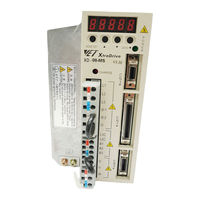
OMRON XtraDrive XD Series User Manual (333 pages)
AC Servo Driver
Brand:
OMRON
| Category:
Computer Hardware
| Size: 7 MB
Table of Contents
Safety Information
5
Table of Contents
7
Safety Precautions
14
Maintenance and Inspection
15
General Precautions
16
Chapter 1 Checking Product and Part Names
17
Checking the Xtradrive Series Products on Delivery
18
Checking Product and Part Names
18
Servo Amplifiers
19
Product Part Names
19
Model Numbers
20
Installation
21
Servo Amplifiers
22
Storage Conditions
22
Installation Site
22
Orientation
23
Installation
23
Chapter 3 Wiring
25
Connecting to Peripheral Devices
26
Single-Phase 200V Main Circuit Specifications
27
Single-Phase 0.8Kw 200V Main Circuit Specifications
28
Three-Phase 200V Main Circuit Specifications
29
Three-Phase 400V Main Circuit Specifications
30
Xtradrive Internal Block Diagrams
31
Single-Phase 30W to 800W, 200V Models
31
Three-Phase 1Kw to 3Kw, 200V Models
32
Three-Phase 0.5Kw to 3.0Kw, 400V Models
33
Main Circuit Wiring
34
Names and Descriptions of Main Circuit Terminal
35
Typical Main Circuit Wiring Example
36
Servo Amplifier Power Losses
37
Wiring Main Circuit Terminal Blocks
38
I/O Signals
39
Example of Typical I/O Signal Connections
39
List of CN1 Terminals
40
I/O Signal Names and Functions
41
Output Signals
42
Interface Circuits
43
Wiring Encoders (for SGMGH and SGMSH Motors Only)
47
Encoder Connections
47
CN2 Encoder Connector Terminal Layout and Types
49
Encoder Cables Interconnections
50
Examples of Standard Connections
52
Chapter 4 Trial Operation
58
Two-Step Trial Operation
58
Step 1: Trial Operation for Servomotor Without Load
59
Step 2: Trial Operation with Servomotor Connected to Machine
65
Additional Setup Procedures in Trial Operation
66
Servomotors with Brakes
66
Position Control by Host Controller
67
Basic Parameters
68
Minimum Parameters and Input Signals
68
Parameters
68
Speed Control
68
Input Signals
68
Chapter 5 Parameter Settings and Functions
69
Parameters
71
Settings According to Device Characteristics
72
Switching Servomotor Rotation Direction
72
Setting the Overtravel Limit Function
73
Limiting Torque
76
Settings According to Host Controller
80
Speed Reference
80
Position Reference
82
Using the Encoder Signal Output
88
Sequence I/O Signals
91
Using the Electronic Gear Function
93
Contact Input Speed Control
97
Using Torque Control
102
Default Settings
105
Torque Feed-Forward Function
108
Torque Limiting by Analog Voltage Reference
110
Reference Pulse Inhibit Function (/INHIBIT)
112
Setting up the Servo Amplifier
113
Parameters
113
JOG Speed
114
Input Circuit Signal Allocation
114
Output Circuit Signal Allocation
118
Control Mode Selection
120
Setting Stop Functions
122
Adjusting Offset
122
Servo off Stop Mode Selection
123
Using the Zero Clamp Function
124
Using the Holding Brake
126
Forming a Protective Sequence
129
Using Servo Alarm and Alarm Code Outputs
129
Using the Servo on Input Signal (/S-ON)
131
Using the Positioning Completed Output Signal (/COIN)
132
Speed Coincidence Output (/V-CMP)
133
Using the Running Output Signal (/TGON)
135
Using the Servo Ready Output Signal (/S-RDY)
136
Using the Warning Output Signal (/WARN)
137
Handling Power Loss
139
Selecting a Regenerative Resistor
140
External Regenerative Resistor
141
Calculating the Regenerative Power Capacity
142
Absolute Encoders
146
Interface Circuit
147
Configuring an Absolute Encoder
148
Absolute Encoder Setup
149
Absolute Encoder Reception Sequence
152
AB Encoders
157
Configuration of Serial Commands for AB Encoders
159
Position Control
159
Defining User Units for Motion Profiles
159
Position Units
159
Speed Units
160
Acceleration Units
161
Setting Default Motion Profile Parameters
162
Profile Speed (Pn2A2, Pn2A3)
163
Profile Acceleration (Pn2A4, Pn2A5)
163
Jerk Smoothing Time (Pn2A6)
163
Quick Stop Deceleration (Pn2A8, Pn2A9)
164
Motion End Window (Pn2C0)
164
Torque Control
164
Torque Slope (Pn2C1)
164
Homing
165
Digital I/O
166
Auto Tuning
167
Auto Running a User Program
167
Chapter 6 Servo Adjustment
168
Selection of Control Mode
169
Analog Input or Contact Input Velocity Control
170
Principle and Block Diagram of the Velocity Control
170
Parameters of the Velocity Control
171
Setting the Input Gain
171
Adjusting Offset
172
Using the Soft Start Function
173
Load Inertia Setting
174
Adjusting Speed Loop Gain
175
Setting the Torque Reference Filter Time Constant
176
Notch Filter
176
Gain Setting Reference Values
177
NCT Position Control
179
Load Inertia Setting
179
Position Control Block Diagram
181
NCT Gain Parameters
182
OCA - Oscillation Canceling Algorithm
183
Additional Parameters Tuning
184
Filters
184
Flexible System Parameters
185
Gain Factor
186
Integral Clear Parameters
186
Tuning Procedure for Position Control Parameters
188
Analog Monitor
190
Chapter 7 Using the Panel Operator
192
Basic Operation
193
Panel Operator
193
Resetting Servo Alarms
194
Basic Mode Selection
194
Status Display Mode
195
Operation in Parameter Setting Mode
197
Operation in Monitor Mode
202
Applied Operation
207
Operation in Alarm Traceback Mode
208
JOG Operation
209
Automatic Adjustment of Speed and Torque Reference Offset
211
Automatic Adjustment of the Speed and Torque Reference Offset
211
Manual Adjustment of Speed and Torque Reference Offset
213
Manual Adjustment of the Speed and Torque Reference Offset
213
Clearing Alarm Traceback Data
216
Checking the Motor Model
217
Checking the Software Version
218
Origin Search Mode
219
Origin Search Model
219
Initializing Parameter Settings
221
Manual Zero Adjustment and Gain Adjustment of Analog Monitor Output
222
Adjusting the Motor Current Detection Offset
225
Write Protection Setting
227
Clearing the Option Unit Detection Alarm
228
Chapter 8 Ratings, Specifications and Dimensional Drawings
233
Single-Phase 200V Xtradrive and Motors Combinations
235
Three-Phase 200V Xtradrive and Motor Combinations
236
Three-Phase 400V Xtradrive and Motors Combinations
237
Base-Mounted Dimensional Drawings
239
XD-P3 to -02 (1-Phase 200V, 30 to 200 W)
239
1-Phase 200 V, 400 W)
240
1-Phase 200V, 0.75Kw) and XD-10 (3-Phase 200V, 1.0Kw)
241
1-Phase 200V,0.75Kw)And XD-10(3-Phase 200V, 1.0Kw)
241
XD-05, 10, 15 (3-Phase 400V, 0.5 to 1.5Kw)
242
XD-20, -30 (3-Phase 200V,400V, 2.0 and 3.0 Kw)
243
Rack-Mounted Dimensional Drawings
244
XD-P3 to -02 (1-Phase 200V, 30 to 200 W)
244
1-Phase 200 V, 400 W)
245
1-Phase 200V, 0.75Kw) and XD-10 (3-Phase 200V, 1.0Kw)
246
1-Phase 200V, 0.75Kw)And XD-10(3-Phase 200V,1.0Kw)
246
XD-05, 10, 15 (3-Phase 400V, 0.5 to 1.5Kw)
247
XD-20, -30 (3-Phase 200V,400V, 2.0 and 3.0 Kw)
248
Chapter 9 Inspection, Maintenance, and Troubleshooting
250
Xtradrive Inspection and Maintenance
250
Servomotor Inspection
250
Servo Amplifier Inspection
250
Replacing the Battery for the Absolute Encoder
251
Troubleshooting
252
Troubleshooting Problems with Alarm Displays
252
Troubleshooting Problems with no Alarm Display
273
Alarm Display Table
274
Warning Displays
276
Appendix A. Host Controller Connection Examples
278
Connecting the GL-Series MC20 Motion Module
278
Connecting the CP-9200SH Servo Controller Module (SVA
279
Connecting the GL-Series B2813 Positioning Module
280
Connecting Omron's C500-NC222 Position Control Unit
281
Connecting Omron's C500-NC112 Position Control Unit
282
Connecting Mitsubishi's AD72 Positioning Unit
283
Connecting Mitsubishi's AD75 Positioning Unit
284
Xtradrive User Manual Appendix B: Special Wiring
286
B.1. Wiring Precautions
286
Wiring for Noise Control
289
Using more than One Xtradrive
293
Extending Encoder Cables
294
Power Supply Voltage
296
B.5. 400V Power Supply Voltage
296
Reactor for Harmonic Suppression
298
Appendix B. Special Wiring
286
Wiring Precautions
286
Appendix C. Specifications for Peripheral Devices
299
Connector Terminal Block Converter Unit JUSP-TA50P
300
External Regenerative Resistors
302
Dimensional Drawings
303
DC Reactors for Power Supplies Designed for Minimum Harmonics
304
Brake Power Supplies
306
Surge Suppressor
306
Surge Suppressor
307
Magnetic Contactor
307
C.5. Surge Suppressor
307
C.6. Magnetic Contactor
307
Variable Resistor for Speed Setting
307
CN1 I/O Signal Connector
307
Connecting Pulse A/B Encoder Without C Pulse (Index Pulse
308
Absolute Encoder Battery
309
Cables for Connecting PC to Xtradrive
310
Communication Cable
310
C.11.1. RS-232 Communication Cable
310
Cable with RS-232 to RS-422 Active Adapter
312
Connecting Regenerative Resistors
313
Connecting Yaskawa Option Board
317
Attaching the Option Board
317
Detaching the Option Board
317
Appendix D. List of Parameters
318
Parameters
319
D.1. Parameters
319
This Appendix Lists the Parameters, Switches, and Input Signal Selections, out Put
323
Parameters
323
Switches
324
D.2. Switches
324
Input Signal Selections
328
Home Switches
329
D.3.1. Home Switches
329
Extended Input Signal Selection
329
Output Signal Selections
330
Extended Output Signal Selection
330
Auxiliary Functions
331
Monitor Modes
331
D.5. Auxiliary Functions
331
D.6. Monitor Modes
331
Advertisement
Omron XtraDrive XD Series User Manual (335 pages)
AC Servo Driver
Brand:
Omron
| Category:
Servo Drives
| Size: 10 MB
Table of Contents
Table of Contents
8
Checking Product and Part Names
18
Checking Product and Part Names
19
Checking the Xtradrive Series Products on Delivery
19
Product Part Names
20
Servo Amplifiers
20
Model Numbers
21
Installation
22
Installation Site
23
Servo Amplifiers
23
Storage Conditions
23
Installation
24
Orientation
24
Wiring
26
Connecting to Peripheral Devices
27
Single-Phase 200V Main Circuit Specifications
28
Single-Phase 0.8Kw 200V Main Circuit Specifications
29
Three-Phase 200V Main Circuit Specifications
30
Three-Phase 400V Main Circuit Specifications
31
Single-Phase 30W to 800W, 200V Models
32
Xtradrive Internal Block Diagrams
32
Three-Phase 1Kw to 3Kw, 200V Models
33
Three-Phase 0.5Kw to 3.0Kw, 400V Models
34
Main Circuit Wiring
35
Names and Descriptions of Main Circuit Terminal
36
Typical Main Circuit Wiring Example
37
Servo Amplifier Power Losses
38
Wiring Main Circuit Terminal Blocks
39
Example of Typical I/O Signal Connections
40
I/O Signals
40
List of CN1 Terminals
41
I/O Signal Names and Functions
42
Interface Circuits
44
Encoder Connections
48
Wiring Encoders (for SGMGH and SGMSH Motors Only)
48
CN2 Encoder Connector Terminal Layout and Types
50
Encoder Cables Interconnections
51
Examples of Standard Connections
53
Trial Operation
59
Two-Step Trial Operation
59
Step 1: Trial Operation for Servomotor Without Load
60
Step 2: Trial Operation with Servomotor Connected to Machine
66
Additional Setup Procedures in Trial Operation
67
Servomotors with Brakes
67
Position Control by Host Controller
68
Input Signals
69
Minimum Parameters and Input Signals
69
Parameters
69
Parameter Settings and Functions
70
Parameters
72
Settings According to Device Characteristics
73
Switching Servomotor Rotation Direction
73
Setting the Overtravel Limit Function
74
Limiting Torque
77
Settings According to Host Controller
81
Speed Reference
81
Position Reference
83
Using the Encoder Signal Output
89
Sequence I/O Signals
92
Using the Electronic Gear Function
94
Contact Input Speed Control
98
Using Torque Control
103
Torque Feed-Forward Function
109
Torque Limiting by Analog Voltage Reference
111
Reference Pulse Inhibit Function (/INHIBIT)
113
Parameters
114
Setting up the Servo Amplifier
114
Input Circuit Signal Allocation
115
JOG Speed
115
Output Circuit Signal Allocation
119
Control Mode Selection
121
Adjusting Offset
123
Setting Stop Functions
123
Servo off Stop Mode Selection
124
Using the Zero Clamp Function
125
Using the Holding Brake
127
Forming a Protective Sequence
130
Using Servo Alarm and Alarm Code Outputs
130
Using the Servo on Input Signal (/S-ON)
132
Using the Positioning Completed Output Signal (/COIN)
133
Speed Coincidence Output (/V-CMP)
134
Using the Running Output Signal (/TGON)
136
Using the Servo Ready Output Signal (/S-RDY)
137
Using the Warning Output Signal (/WARN)
138
Handling Power Loss
140
Selecting a Regenerative Resistor
141
External Regenerative Resistor
142
Calculating the Regenerative Power Capacity
143
Absolute Encoders
147
Interface Circuit
148
Configuring an Absolute Encoder
149
Absolute Encoder Setup
150
Absolute Encoder Reception Sequence
153
AB Encoders
158
Configuration of Serial Commands for AB Encoders
160
Defining User Units for Motion Profiles
160
Position Control
160
Position Units
160
Speed Units
161
Acceleration Units
162
Speed Units
162
Setting Default Motion Profile Parameters
163
Jerk Smoothing Time (Pn2A6)
164
Profile Acceleration (Pn2A4, Pn2A5)
164
Profile Speed (Pn2A2, Pn2A3)
164
Motion End Window (Pn2C0)
165
Quick Stop Deceleration (Pn2A8, Pn2A9)
165
Torque Control
165
Torque Slope (Pn2C1)
165
Homing
166
Digital I/O
167
Auto Running a User Program
168
Auto Tuning
168
Servo Adjustment
169
Selection of Control Mode
170
Analog Input or Contact Input Velocity Control
171
Principle and Block Diagram of the Velocity Control
171
Parameters of the Velocity Control
172
Setting the Input Gain
172
Adjusting Offset
173
Using the Soft Start Function
174
Load Inertia Setting
175
Adjusting Speed Loop Gain
176
Notch Filter
177
Setting the Torque Reference Filter Time Constant
177
Gain Setting Reference Values
178
Load Inertia Setting
180
NCT Position Control
180
Position Control Block Diagram
182
NCT Gain Parameters
183
OCA - Oscillation Canceling Algorithm
184
Additional Parameters Tuning
185
Filters
185
Flexible System Parameters
186
Gain Factor
187
Integral Clear Parameters
187
Tuning Procedure for Position Control Parameters
189
Analog Monitor
191
Using the Panel Operator
193
Basic Operation
194
Panel Operator
194
Basic Mode Selection
195
Resetting Servo Alarms
195
Status Display Mode
196
Operation in Parameter Setting Mode
198
Operation in Monitor Mode
203
Applied Operation
208
Operation in Alarm Traceback Mode
209
JOG Operation
210
Automatic Adjustment of Speed and Torque Reference Offset
212
Automatic Adjustment of the Speed and Torque Reference Offset
212
Manual Adjustment of Speed and Torque Reference Offset
214
Clearing Alarm Traceback Data
217
Checking the Motor Model
218
Checking the Software Version
219
Origin Search Mode
220
Origin Search Model
220
Initializing Parameter Settings
222
Manual Zero Adjustment and Gain Adjustment of Analog Monitor Output
223
Adjusting the Motor Current Detection Offset
226
Write Protection Setting
228
Clearing the Option Unit Detection Alarm
229
Ratings, Specifications and Dimensional Drawings
233
Single-Phase 200V Xtradrive and Motors Combinations
236
Three-Phase 200V Xtradrive and Motor Combinations
237
Three-Phase 400V Xtradrive and Motors Combinations
238
Three-Phase 400V Xtradrive and Motors Combinations
239
Base-Mounted Dimensional Drawings
240
XD-P3 to -02 (1-Phase 200V, 30 to 200 W)
240
1-Phase 200 V, 400 W)
241
1-Phase 200V, 0.75Kw) and XD-10 (3-Phase 200V, 1.0Kw)
242
1-Phase 200V,0.75Kw)And XD-10(3-Phase 200V, 1.0Kw)
242
XD-05, 10, 15 (3-Phase 400V, 0.5 to 1.5Kw)
243
XD-20, -30 (3-Phase 200V,400V, 2.0 and 3.0 Kw)
244
Rack-Mounted Dimensional Drawings
245
XD-P3 to -02 (1-Phase 200V, 30 to 200 W)
245
1-Phase 200 V, 400 W)
246
1-Phase 200V, 0.75Kw) and XD-10 (3-Phase 200V, 1.0Kw)
247
1-Phase 200V, 0.75Kw)And XD-10(3-Phase 200V,1.0Kw)
247
XD-05, 10, 15 (3-Phase 400V, 0.5 to 1.5Kw)
248
XD-20, -30 (3-Phase 200V,400V, 2.0 and 3.0 Kw)
249
Inspection, Maintenance, and Troubleshooting
251
Servo Amplifier Inspection
251
Servomotor Inspection
251
Xtradrive Inspection and Maintenance
251
Replacing the Battery for the Absolute Encoder
252
Troubleshooting
253
Troubleshooting Problems with Alarm Displays
253
Troubleshooting Problems with no Alarm Display
274
Alarm Display Table
275
Warning Displays
277
Appendix A. Host Controller Connection Examples
279
Connecting the GL-Series MC20 Motion Module
279
Connecting the CP-9200SH Servo Controller Module (SVA
280
Connecting the GL-Series B2813 Positioning Module
281
Connecting Omron's C500-NC222 Position Control Unit
282
Connecting Omron's C500-NC112 Position Control Unit
283
Connecting Mitsubishi's AD72 Positioning Unit
284
Connecting Mitsubishi's AD75 Positioning Unit
285
Appendix B. Special Wiring
287
Wiring Precautions
287
Wiring for Noise Control
290
Using more than One Xtradrive
294
Extending Encoder Cables
295
Power Supply Voltage
297
Reactor for Harmonic Suppression
299
Connector Terminal Block Converter Unit JUSP-TA50P
301
External Regenerative Resistors
303
DC Reactors for Power Supplies Designed for Minimum Harmonics
305
Brake Power Supplies
307
Surge Suppressor
307
Surge Suppressor
308
Magnetic Contactor
308
Variable Resistor for Speed Setting
308
CN1 I/O Signal Connector
308
Connecting Pulse A/B Encoder Without C Pulse (Index Pulse
309
Absolute Encoder Battery
310
Cables for Connecting PC to Xtradrive
311
Communication Cable
311
Cable with RS-232 to RS-422 Active Adapter
313
Connecting Regenerative Resistors
314
Connecting Yaskawa Option Board
318
Attaching the Option Board
318
Detaching the Option Board
318
Appendix D. List of Parameters
319
Parameters
320
Switches
325
Input Signal Selections
329
Home Switches
330
Extended Input Signal Selection
330
Output Signal Selections
331
Extended Output Signal Selection
331
Auxiliary Functions
332
Monitor Modes
332
Advertisement
Related Products
OMRON XTRADRIVE -
Omron XtraDrive XD-P3-M Series
Omron XtraDrive XD-P5-M Series
Omron XtraDrive XD-08-M Series
Omron XtraDrive XD-15-M Series
Omron XtraDrive XD-20-T Series
Omron XtraDrive XD-30-T Series
Omron XtraDrive XD-50-T Series
Omron XtraDrive XD-15-T Series
Omron XtraDrive XD-10-T Series
Omron Categories
Blood Pressure Monitor
Controller
Accessories
Switch
Inverter
More Omron Manuals
Login
Sign In
OR
Sign in with Facebook
Sign in with Google
Upload manual
Upload from disk
Upload from URL