
Related Manuals for Omron CS1W-CRM21


Summary of Contents for Omron CS1W-CRM21
- Page 1 Cat. No. W456-E1-03 CompoNet CS1W-CRM21/CJ1W-CRM21 CompoNet Master Units OPERATION MANUAL...
- Page 3 CompoNet CS1W-CRM21/CJ1W-CRM21 CompoNet Master Units Operation Manual Revised March 2009...
- Page 5 OMRON. No patent liability is assumed with respect to the use of the information contained herein. Moreover, because OMRON is con- stantly striving to improve its high-quality products, the information contained in this manual is subject to change without notice.
- Page 7 TABLE OF CONTENTS PRECAUTIONS ........Intended Audience ............General Precautions .
-
Page 8: Table Of Contents
TABLE OF CONTENTS SECTION 6 Message Communications ......151 Message Communications ........... Overview of FINS Commands and Responses . -
Page 9: About This Manual
About this Manual: This manual describes the installation and operation of the CS1W-CRM21 and CJ1W-CRM21 Compo- Net Master Units and includes the sections described below. Please read this manual carefully and be sure you understand the information provided before attempting to install or operate a CompoNet Master Unit. Be sure to read the precautions provided in the following section. - Page 11 WHETHER SUCH CLAIM IS BASED ON CONTRACT, WARRANTY, NEGLIGENCE, OR STRICT LIABILITY. In no event shall the responsibility of OMRON for any act exceed the individual price of the product on which liability is asserted. IN NO EVENT SHALL OMRON BE RESPONSIBLE FOR WARRANTY, REPAIR, OR OTHER CLAIMS...
-
Page 12: Application Considerations
Application Considerations SUITABILITY FOR USE OMRON shall not be responsible for conformity with any standards, codes, or regulations that apply to the combination of products in the customer's application or use of the products. At the customer's request, OMRON will provide applicable third party certification documents identifying ratings and limitations of use that apply to the products. - Page 13 Performance data given in this manual is provided as a guide for the user in determining suitability and does not constitute a warranty. It may represent the result of OMRON's test conditions, and the users must correlate it to actual application requirements. Actual performance is subject to the OMRON Warranty and Limitations of Liability.
- Page 15 PRECAUTIONS This section provides general precautions for using the CS1W-CRM21 and CJ12-CRM21 CompoNet Master Units. The information contained in this section is important for the safe and reliable application of the CompoNet Master Units. You must read this section and understand the information contained before attempting to set up or operate a CompoNet Network using CompoNet Master Units.
-
Page 16: Intended Audience
It is extremely important that a PLC and all PLC Units be used for the speci- fied purpose and under the specified conditions, especially in applications that can directly or indirectly affect human life. You must consult with your OMRON representative before applying a PLC System to the above-mentioned appli- cations. -
Page 17: Operating Environment Precautions
Operating Environment Precautions !WARNING Provide safety measures in external circuits (i.e., not in the Programmable Controller), including the following items, to ensure safety in the system if an abnormality occurs due to malfunction of the PLC or another external factor affecting the PLC operation. -
Page 18: Application Precautions
Application Precautions Application Precautions Observe the following precautions when using a CompoNet Network. • When more than one CompoNet system use Flat Cables, always sepa- rate the Flat Cables from each other by at least 5 mm regardless of whether Flat Cable I or II cables are used. Do not bundle the Flat Cables. This is to prevent unstable operation of the system due to interference. - Page 19 Application Precautions • Take appropriate measures to ensure that the specified power with the rated voltage and frequency is supplied. Be particularly careful in places where the power supply is unstable. An incorrect power supply may result in malfunction. • Do not apply voltages to the Input Units in excess of the rated input volt- age.
-
Page 20: Conformance To Ec Directives
Concepts EMC Directives OMRON devices are designed so that they comply with the related EMC Directives so that they can be more easily built into other devices or the over- all machine. The actual products have been checked for conformity to EMC Directives (see the following note). -
Page 21: Conformance To Ec Directives
Applicability of the shipbuilding standards is based on certain usage conditions. It may not be possible to use a Master Unit in some loca- tions. Contact your OMRON representative before attempting to use a Master Unit on a ship. - Page 22 Conformance to Shipbuilding Standards xxii...
- Page 23 SECTION 1 Overview This section provides an overview of CompoNet networks. CompoNet Networks..........1-1-1 Overview.
-
Page 24: Componet Networks
CompoNet Networks Section 1-1 CompoNet Networks 1-1-1 Overview CompoNet Networks feature easy operation and installation in a component- level network connecting PLCs and on-site I/O. The PLC and CompoNet Slave Units cyclically exchange I/O information through a CompoNet Master Unit, refreshing I/O in sync with the PLC scan. Message communications can also be used from host computers or the CPU Unit of the PLC to read and write CompoNet Slave Unit data. - Page 25 Section 1-1 CompoNet Networks Communications Cables CompoNet Networks use Round Cable I, Round Cable II, Flat Cable I (DCA4- 4F10 Standard Flat Cable), and Flat Cable II (DCA5-4F10 Sheathed Flat Cable) for Communications Cables. Master Unit The Master Unit manages the CompoNet Network and transfers I/O data between the PLC and the Slave Units.
-
Page 26: System Configuration Patterns
CompoNet Networks Section 1-1 • Sub-branch line: The transmission path created using a T-branch from a branch line. (T-branching is not possible from sub-branch lines.) Note Due to differences in functionality, the same type of cable must be used between the trunk line and a branch line, a sub-trunk line and a branch line, and a branch line and a sub-branch line. -
Page 27: Features Of Componet Networks
Section 1-1 CompoNet Networks 1-1-4 Features of CompoNet Networks Programless With the use of only Round Cable I, Round Cable II, Flat Cable I and Flat Communications Cable II cables, cyclic data exchange or remote I/O communications can be achieved between a Master Unit mounted in a PLC and multiple Slave Units. High-speed Multi-point Remote I/O communications for up to 2,560 I/O points can be achieved at Processing... - Page 28 Section 1-1 CompoNet Networks • Editing and transferring registration tables • Setting Input Data Zero Clear Mode for when communications error occur • Setting I/O Communications Manual Startup Mode • Monitoring Master Unit status • Monitoring the Master Unit error history •...
-
Page 29: Componet Network Specifications
CompoNet Network Specifications Section 1-2 ■ Communications Error Input Data Zero Clear Mode Input Data Zero Clear Mode can be set from the CX-Integrator for communi- cations error. If a communications error occurs for a Slave Unit in this mode, all input data for that Slave Unit will be cleared to zeros. - Page 30 Section 1-2 CompoNet Network Specifications Item Specifications Repeater Unit application conditions Up to 64 Repeater Units can be connected per network (i.e., per Master Unit). Up to 32 Repeater Units can be connected per trunk line or per sub-trunk line. When Repeater Units are connected in series from the Master Unit, up to two extra segment layers can be created (i.e., up to 2 Repeater Units are allowed between a Slave Unit and the Master Unit).
-
Page 31: Cable Types, Maximum Distances, And Number Of Slave Units
Section 1-2 CompoNet Network Specifications Item Specifications Slave Unit Without Registration Table Participation Flag and Communications Error Flag for each Slave Unit status • Participation Flag: Turns ON and remains ON if the Slave Unit joins the net- work even one time after system power is turned ON. •... - Page 32 Section 1-2 CompoNet Network Specifications ■ Baud Rate of 3 Mbps Item Round Cable I or II Flat Cable I or II Length per trunk line or sub-trunk line (maximum 30 m (90 m) 30 m (90 m) length with two Repeater Units) Branch line length 0.5 m 0.5 m...
-
Page 33: Branch Line Support For Cable Types And Baud Rates
CompoNet Network Specifications Section 1-2 ■ Baud Rate of 93.75 kbps Item Round Cable I or II Flat Cable I or II Length per trunk line or sub-trunk line(maximum 500 m (1500 m) Unrestricted wiring is enabled length with two Repeater Units) for a total length of 200 m. -
Page 34: Allocating Slave Units In The Cpu Unit Memory Area By Communications Mode Number
CompoNet Network Specifications Section 1-2 1-2-3 Allocating Slave Units in the CPU Unit Memory Area by Communications Mode Number Slave Unit I/O information and status information is allocated in the Special I/O Unit memory area or a user-specified area of the CPU Unit to which the Master Unit is mounted. -
Page 35: Devices In A Componet Network
Section 1-3 Devices in a CompoNet Network Note (1) In a CompoNet Network, Word Slave Units have 16 bits per node ad- dress. Bit Slave Units have two bits allocated per node address. (2) Do not use the reserved communications mode numbers (4 to 7 and 9). A communications mode setting error (H4 at the 7-segment LED indica- tor) will occur if any of these mode numbers is set. -
Page 36: Peripheral Devices
Devices in a CompoNet Network Section 1-3 1-3-2 Peripheral Devices Communications Cables The following table shows the Communications Cables that can be used in a CompoNet Network. Name Model Specifications Remarks Round Cable I JIS C 3306 Cannot be used with Bit Slave Units. - Page 37 Section 1-3 Devices in a CompoNet Network ■ Flat Cable II Communications Cables (Yes: Can be used. No: Cannot be used.) Name Model Appearance Application Round Round Flat Flat Cable I Cable II Cable I Cable II Flat Connector DCN5-TR4 Use this Connector in a set with Socket a DCN5-BR4 Flat Connector...
- Page 38 Section 1-3 Devices in a CompoNet Network ■ Flat Cable II Communications Cables (Yes: Can be used. No: Cannot be used.) Name Model Appearance Application Round Round Flat Flat Cable I Cable II Cable I Cable II Flat Connector DCN5-BR4 a.
-
Page 39: Special Tools
Devices in a CompoNet Network Section 1-3 Special Tools Communications Cables (Yes: Can be used. Name Model Appearance Application No: Cannot be used.) Round Round Flat Flat Cable I Cable II Cable I Cable II Special Tool (Pli- DWT-A01 A pressure welding tool for ers) DCN4-TR4 Flat Connec- tor Socket and a DCN4-... -
Page 40: Selecting Peripheral Devices Used According To Connection Configuration
Section 1-3 Devices in a CompoNet Network 1-3-3 Selecting Peripheral Devices Used According to Connection Configuration Flat Cable I, Round Cable I, or Round Cable II Connection configuration Peripheral Devices used Connecting the Master Unit Connecting the trunk line to the Master Flat Connector Plug (DCN4-BR4) only, or Open Unit Type Connector (to connect Units to the Cable) -
Page 41: Overview Of Design Flow
Section 1-4 Overview of Design Flow Overview of Design Flow Perform the following steps to design the system. 1. Determine the number of I/O points..Refer to 1-2 CompoNet Net- work Specifications and 1-3 Determine the number of I/O points in the entire system. Devices in a CompoNet Net- ▼... -
Page 42: Overview Of Operating Procedure
Section 1-5 Overview of Operating Procedure Overview of Operating Procedure Follow the steps below to install and use a CompoNet Network. 1. Install and wire the system..SECTION 4 Installation and Wiring Wire the network, the communications power supply, and the I/O power supply. -
Page 43: Design And Operating Procedure Examples
Design and Operating Procedure Examples Section 1-6 Design and Operating Procedure Examples 1-6-1 Design I/O Capacity Establish the I/O correspondences for each Slave Unit. Determine how many Word and Bit Slave Units are to be connected, and calculate the current con- sumption for the communications power supply. - Page 44 Design and Operating Procedure Examples Section 1-6 System Configuration Computer (CX-Integrator) CJ-series CPU Unit CJ-series Master Unit CJ-series PLC CompoNet Flat Cable 16 inputs 16 inputs + 8 outputs 16 outputs 2 inputs 2 inputs 2 outputs BIT#0 BIT#1 BIT#2 Word Slaves Bit Slaves Layout...
- Page 45 Section 1-6 Design and Operating Procedure Examples Maximum Length for Trunk Lines and Sub-trunk Lines • When the lines are 30 m or less: Any combination of cable types and baud rates is supported. • When a distance longer than 30 m is required: •...
- Page 46 Design and Operating Procedure Examples Section 1-6 Types of Cables Flat Cable is used in this example, because IP20 Bit Slave Units are used and the communications power supply is provided collectively through the commu- nications cables. Cable type Item Round Cable I Round Cable II Flat Cable I...
- Page 47 Section 1-6 Design and Operating Procedure Examples Cable type Item Round Cable I Round Cable II Flat Cable I Flat Cable II Communica- 4 Mbps Length of the trunk line or a sub-trunk line: 30 m max tions distance 3 Mbps Length of the trunk line or a sub-trunk line: 30 m max 1.5 Mbps Length of the...
- Page 48 Section 1-6 Design and Operating Procedure Examples I/O Allocations Word address Bit 15 Bit 0 Special I/O 2050 [ OUT0 ] Not used. Unit Memory OUT 1 (CIO 2051, bits 00 to 07) : XWT-OD08 2051 Not used. [ OUT1 ] XWT-OD08 Area 2052 [ OUT2] CRT1-OD16...
-
Page 49: Operating Procedure
Design and Operating Procedure Examples Section 1-6 1-6-2 Operating Procedure 1,2,3... 1. Perform the installation and wiring. CX-Integrator CS/CJ-series CPU Unit CompoNet Master Unit DCA4-4F10 Flat Cable I DCN4-BR4 Flat Connector Plug Length: 100 m Serial connection DCN4-TR4 DCN4-TR4 DCN4-TR4 Flat Connector Socket Flat Connector Socket Flat Connector Socket... - Page 50 Section 1-6 Design and Operating Procedure Examples • Communications Error Communications Stop Mode (Stopping All Remote I/O Communications when a Communications Error Occurs in One Slave Unit) and Registration Table Enable Setting Name ESTP (Communications Communications stop Communications do not Error Communications when a communications stop when a communica-...
- Page 51 Section 1-6 Design and Operating Procedure Examples (5) Open the Detailed Settings Dialog Box and enable the Registered Slave Unit Participation Standby Mode. (6) Click the Download Button to download the Master Unit device param- eters. 9. Cycle the power to the PLC. 10.
- Page 52 Section 1-6 Design and Operating Procedure Examples Indicators and Seven- • Normal Operation segment Display Indicators Status Display Seven-segment display Contents _0 to _3 lit Remote I/O communications are 4 Mbps starting. 3 Mbps 1.5 Mbps 93.75 kbps • Error Operation Indicators Status Seven-segment display...
- Page 53 Section 1-6 Design and Operating Procedure Examples 11. Using the CX-Integrator, monitor the participation status of Slave Units. (1) While online, upload the network configuration. (2) Right-click the Master Unit in the Network Configuration Window, and select Monitor. (3) Monitor Slave Unit participation status on the Slave Status Tab Page. A list of node addresses will be displayed showing the participation sta- tus for each node: participating (blue), disconnected (red), or not par- ticipating (gray).
- Page 54 Section 1-6 Design and Operating Procedure Examples...
- Page 55 SECTION 2 Master Units This section provides the specifications of the CompoNet Master Units Master Unit Specifications ........2-1-1 Specifications .
-
Page 56: Master Unit Specifications
Section 2-1 Master Unit Specifications Master Unit Specifications 2-1-1 Specifications Item Specification Model CS1W-CRM21 CJ1W-CRM21 Applicable PLC CS Series CJ Series Unit classification CS-series Special I/O Unit CJ-series Special I/O Unit Current consumption (Power sup- 400 mA max. at 5 VDC 400 mA max. -
Page 57: Component Names And Functions
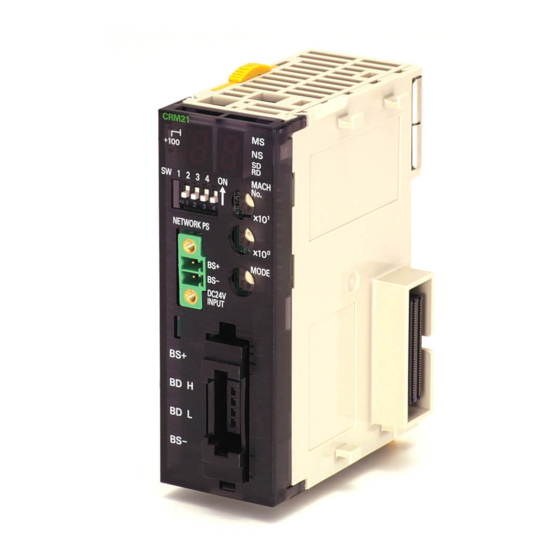
Section 2-1 Master Unit Specifications 2-1-2 Component Names and Functions CS-series Master Unit Display Section Shows the Master Unit status and Slave Unit communications status. · Indicators Four LED indicators: CRM21 MS (green/red), NS (green/red), SD (yellow), and RD (yellow) +100 ·... - Page 58 Section 2-1 Master Unit Specifications CJ-series Master Unit Display Section Shows the Master Unit status and Slave Unit communications status. · Indicators CRM21 Four LED indicators: +100 MS (green/red), NS (green/red), SD (yellow), and RD (yellow) · Seven-segment Display Displays the communications status, error code, etc. SW 1 2 3 4 MACH (two digits plus a dot that indicates "+100")
-
Page 59: Display Section
Section 2-1 Master Unit Specifications 2-1-3 Display Section Communications The following LED indicators are provided for communications. Indicators MS (Module Status): Shows the status of the node itself. (Two colors: green and red) NS (Network Status): Shows the status of communications. (Two colors: green and red) SD (Send Data): Shows Master Unit transmission status. - Page 60 Section 2-1 Master Unit Specifications Status Display Display Actual display Contents contents Normal Remote I/O com- Baud rate 4 Mbps munications in display lit. progress 3 Mbps 1.5 Mbps 93.75 kbps Remote I/O com- Baud rate Flashing 4 Mbps munications display flash- stopped ing.
-
Page 61: Switch Settings
Section 2-1 Master Unit Specifications 2-1-4 Switch Settings Unit Number Special I/O Unit unit number setting: Two decimal rotary switches (0 to 99) Switches (MACH No.) This setting is read when the power supply is turned ON to the PLC. MODE Switch Master Unit communications mode number setting: One decimal rotary switch (0 to 9) -
Page 62: Terminal Arrangement
Section 2-1 Master Unit Specifications DIP Switch This setting is read when the power supply is turned ON to the PLC. Baud Rate Setting Baud rate setting 4 Mbps (default) 3 Mbps 1.5 Mbps 93.75 kbps Slave Units automatically detect the baud rate set on SW1 (DR0) and SW2 (DR2). - Page 63 Master Unit Specifications Section 2-1 Note BS+ and BS- output the communications power supply connected to the communications power supply connector. (This is the com- munications power for Slave Units and Repeater Units connected to the trunk line.) This connector does not supply power to the Master Unit.
-
Page 64: Dimensions
Master Unit Specifications Section 2-1 2-1-6 Dimensions CS1W-CRM21 15.7 100.5 CRM21 +100 MACH MODE 1 DR0 2 DR1 3 ESTP 4 REGS NETWORK POWER SUPPLY DC24V INPUT BS + BD H BD L BS - 34.5 Unit: mm CJ1W-CRM21 80.7... -
Page 65: Wiring Configurations
SECTION 3 Wiring Configurations This section describes the configurations of CompoNet Networks. Wiring Formations ..........CompoNet Network Wiring . -
Page 66: Wiring Formations
Wiring Formations Section 3-1 Wiring Formations A CompoNet network can take two wiring formations: Trunk line − Branch line and Unrestricted Wiring. Trunk Line-Branch With this wiring formation, the trunk line is differentiated from branch lines. Line Formation There are restrictions on the number of branches and the number of Units that can be connected. -
Page 67: Componet Network Wiring
Section 3-2 CompoNet Network Wiring The following table shows the conditions and restrictions for each formation. Item Wiring formation Trunk−Branch formation Unrestricted wiring formation Master Unit location At an end of a network Anywhere in a network (not necessarily at an end) Maximum number of Slave 1 or 3 depending on the No restrictions... -
Page 68: Round Cable Ii
Section 3-2 CompoNet Network Wiring Master Unit of Repeater Unit Relay terminal block Terminating Resistor (121 Ω) Communications signal lines (2) BS− Communications Communications Commu- nications Open Type Connector Slave Unit Slave Unit Slave Unit BS− BS− BS− Open Type Connector Communications Communications Communications... -
Page 69: Flat Cable I Or Flat Cable Ii
CompoNet Network Wiring Section 3-2 • Connect the communications power supply (24 VDC) to the communica- tions power supply connector for the Master Unit or Repeater Unit. • Connect DCN4-TM4 Terminating Resistors and DCN4-TR4 Flat Connec- tor Sockets at the ends of the network. Communications power supply connector Master Unit or Repeater Unit... - Page 70 Section 3-2 CompoNet Network Wiring • A Terminating Resistor (DCN4-TM4 or DCN5-TM4) must be connected at the end of the network. Master Unit or Repeater Unit Communications power supply connector Communications Flat Cable I or Flat Cable II power supply, 24 VDC Commu- Communications power supply lines: BS+: red, BS-: black nications...
-
Page 71: Cable Types
Section 3-2 CompoNet Network Wiring 3-2-4 Cable Types Cable Types The four types of cable listed in the following table can be used as the commu- nications cable for a CompoNet Network. Do not use any other cables. Cable Main application Communica- Conductors type... - Page 72 Section 3-2 CompoNet Network Wiring Round Cable II Use a commercially available VCTF cable with four 0.75-mm conductors (JIS C3306) that meets CompoNet specifications. Ask the cable manufacturer for products applicable to CompoNet. Red: BS+ White: BDH Green or Blue: BDL Black: BS−...
- Page 73 Section 3-2 CompoNet Network Wiring Models other than the DCA5-4F10 can also be used as long as they conform to CompoNet specifications. Ask the cable manufacturer for applicable prod- ucts. Note (1) For additional information on applicable cables to CompoNet and their manufacturers, refer to the ODVA home page.
-
Page 74: Connection Methods
Section 3-2 CompoNet Network Wiring 3-2-5 Connection Methods Round Cable I or Round Cable II Master Unit connections Slave Unit/Repeater Cable branches Unit connections T-branch connections Multidrop connections Open Type Connector Open Type Connector Relay terminal block (commer- Open Type Connector cially available product) Trunk line, sub-trunk Open Type Connector... -
Page 75: Branching A Communications Cable
Section 3-2 CompoNet Network Wiring The Master Unit has a communications connector to which a communications cable is connected. Round Cable I or Round The following Open Type Connector is used to connect a Round Cable I or Cable II (Using Open Type Round Cable II cable to the Master Unit. - Page 76 Section 3-2 CompoNet Network Wiring ■ Example for Round Cable I Relay terminal block Slave Unit Note Attach a M3 crimp terminal to the cable wire before you connect the wire to a terminal block. 6.0 mm max. 6.0 mm max. Flat Cable I or Flat Cable II Use a Flat Connector Socket and a Flat Connector Plug.
-
Page 77: Extending The Cable Length
Section 3-2 CompoNet Network Wiring Multidrop Connections Round Cable I or Round Cable II (with an Open Type Connector) DCN4-TB4 Open Type M3 screw terminal block Connector (to connect a Unit to the cable) Communications connector Slave Unit or Repeater Unit Flat Cable I (with a Multidrop Connector) DCN4-BR4... -
Page 78: Connection Locations For Terminating Resistors
Section 3-2 CompoNet Network Wiring DCN4-TR4 Flat DCN4-BR4 Flat Connector Socket Connector Plug 3-2-9 Connection Locations for Terminating Resistors Terminating Resistors must always be connected to the trunk line and each sub-trunk line on the opposite end from the Master Unit or Repeater Unit. Note Do not connect a Terminating Resistor on the end of the Network with the Master Unit. - Page 79 Section 3-2 CompoNet Network Wiring Connecting Terminating Resistors There are three methods that can be used to connect Terminating Resistor. Method 1: Connect a Flat Connector Socket to the trunk line or sub-trunk line and then connect a Terminating Resistor to the Connector. Flat Cable I Flat Cable II Flat Connector...
-
Page 80: 3-2-10 Connection Locations For Communications Power Supply
Section 3-2 CompoNet Network Wiring 3-2-10 Connection Locations for Communications Power Supply Connect the communications power supply as shown in the following dia- grams. Round Cable II, Flat Cable Example for Flat Cable I or II I, or Flat Cable II Communica- tions power supply, 24 VDC... -
Page 81: Installation And Wiring
SECTION 4 Installation and Wiring This section describes how to install and wire a CompoNet Network. Installation........... . 4-1-1 Tools Required for Installation and Wiring . -
Page 82: Installation
Select suitable installation locations accordingly. Master Units Name Model Degree of Applicable peripheral devices protection Master Units CS1W-CRM21 Flat Cable I Peripheral Devices, Flat Cable II Periph- eral Devices, and Round Cable I CJ1W-CRM21 Flat Cable I Peripheral Devices Name Model Degree of... - Page 83 Section 4-1 Installation Installing the Master Unit CS-series Master Unit Use the following procedure to install the CS-series Master Unit. 1,2,3... 1. Mount the Unit to the Backplane by attaching it with the top and bottom hooks. Hook Backplane 2. Properly insert the Unit into the Backplane connector. 3.
- Page 84 Section 4-1 Installation CJ-series Master Unit 1,2,3... 1. Align the connectors and connect the Master Unit. Connector PA205R POWER SYSMAC ERR/ALM CJ1G-CPU 44 PROGRAMMABL E PRPHL CONTROLLER COMM OPEN MCPWR BUSY AC100 -240V INPUT L2/N PERIP HERA L OUTPU T AC240 V DC24V PORT...
- Page 85 Section 4-1 Installation CJ-series Master Unit Remove the sheet after completing wiring.
-
Page 86: Connecting Cables
Section 4-2 Connecting Cables Connecting Cables 4-2-1 Overview This section provides an outline of connecting a CompoNet Network using Round Cable I and Flat Cable I cables. Refer to SECTION 3 Wiring Configurations for information on the configura- tion. Refer to 4-4 Power Supply Wiring for information on supplying communi- cations power. - Page 87 Section 4-2 Connecting Cables Flat Cable I T-branching Note T-branches and a multidrop connections can be used together. DCN4-BR4 Flat Connector Plug DCN4-TR4 Flat Connector Socket DCN4-TR4 Flat Connector DCN4-TR4 Flat Connector Socket T-branch Socket T-branch DCN4-BR4 Flat Connector Plug DCN4-TM4 Terminating DCN4-BR4 Flat Connector Resistor...
-
Page 88: Connecting To Units
Section 4-2 Connecting Cables 4-2-2 Connecting to Units Connecting the Trunk Line to the Master Unit Round Cable I or II A DCN4-TB4 Open Type Connector is used. Orient the Open Type Connector so that surface with the open terminals is facing to the left and press in the Open Type Connector until it clicks into place. - Page 89 Section 4-2 Connecting Cables Be sure the face of the Connector on which line colors are indicated (red, white, blue, and black) is facing to the left and press in the Connector until it clicks into place. Note To remove an inserted Connector, hold the latches on both sides, and pull out the Connector.
-
Page 90: Branching A Communications Cable
Section 4-2 Connecting Cables Note To remove an inserted Connector, hold the latches on both sides, and pull out the Connector. 4-2-3 Branching a Communications Cable There are two ways to branch the trunk line, sub-trunk lines, and branch lines: T-branches and multidrop connections. - Page 91 Section 4-2 Connecting Cables Note Attach a M3 crimp terminal to the cable wire before you connect the wire to a terminal block. 6.0 mm max. 6.0 mm max. Flat Cable I Attach a DCN4-BR4 Flat Connector Plug to a DCN4-TR4 Flat Connector Socket which has already been mounted to the communications cable.
- Page 92 Section 4-2 Connecting Cables Multidrop Connections Round Cable I or II A DCN4-TB4 Open Type Connector is attached to the communications con- nector of a Slave Unit or a Repeater Unit. This converts the communication connector to a M3 screw terminal block. Then the cable wires are connected to the Connector.
-
Page 93: Extending A Communications Cable
Connecting Cables Section 4-2 DCN4-BR4 Flat Connector Plugs DCN4-MD4 Multidrop Connector Slave Unit or Repeater Unit ■ Mounting Procedure 1,2,3... 1. Hold the Multidrop Connector so that the side with the number is facing to the left, and press the Connector to the communications connector of a Slave or a Repeater Unit until it clicks into place. -
Page 94: Connecting Terminating Resistors
Connecting Cables Section 4-2 Flat Cable I Attach a DCN4-BR4 Flat Connector Plug to a DCN4-TR4 Flat Connector Socket which has already been mounted to the communications cable. DCN4-TR4 Flat DCN4-BR4 Flat Connector Socket Connector Plug ■ Mounting Procedure Hold the Flat Connector Plug with the side with the line colors (i.e., red, white, black, and blue) facing down, and push the Flat Connector Plug inward until it clicks into place. - Page 95 Section 4-2 Connecting Cables ■ Connecting Procedure Connect the cable wires to the Terminating Resistor, and tighten the screws. The Terminating Resistor has no polarity. Either wire can be connected to either terminal regardless of their colors. Terminating Resistor Round cable I BDH (black) or BDL (white) BDL (white) or BDH (black) Note...
- Page 96 Connecting Cables Section 4-2 Note To remove a Terminal Resistor which has been attached, hold the latches on both sides of the Resistor, and pull it out. When a Slave Unit or a Repeater Unit has a multidrop connection, the Termi- nal Resistor can be directly attached to the Multidrop Connector that is mounted on the Unit.
-
Page 97: Preparing And Mounting Flat Connectors
Section 4-3 Preparing and Mounting Flat Connectors Preparing and Mounting Flat Connectors When you connect a Terminal Resistor to a Round Cable II cable, connect a Flat Cable I or II cable to the Unit, or when you branch or extend the line, you must prepare a Flat Connector and mount it on the cable. -
Page 98: Round Cable Ii
Section 4-3 Preparing and Mounting Flat Connectors Tools Required Name Appearance Model Application Pliers DWT-A01 Crimping tool for DCN4-TR4 Flat Connector Socket or DCN4-BR4 Flat Connector Plug Pliers DWT-A02 Crimping tool for DCN5-TR4 Flat Connector Socket or DCN5-BR4 Flat Connector Plug 4-3-1 Round Cable II A Flat Connector must be mounted on a Round Cable II cable only when a... - Page 99 Preparing and Mounting Flat Connectors Section 4-3 Cable stopper ■ Connecting the Cable Confirm that the cable colors match the cable labels and then insert the unsheathed cable tip all the way into the cable stopper in the cover. Location of cable stopper ■...
-
Page 100: Flat Cable I
Section 4-3 Preparing and Mounting Flat Connectors 2. Squeeze firmly on the Pliers until the lock on the connector clicks into place. Note (a) Do not pressure-weld the connector cover at the edges. (b) Do not pressure-weld the connector cover at the back of the pres- sure-welding block. - Page 101 Section 4-3 Preparing and Mounting Flat Connectors To prevent short-circuits, use a sharp cutting tool such as nipper. Confirm there is no remaining wire coming out. ■ Setting the Cable Stopper This step is required only for extending the cable or connecting a Terminating Resistor.
- Page 102 Section 4-3 Preparing and Mounting Flat Connectors ■ Extending or Connecting a Terminating Resistor Insert the cable tip all the way into the cable stopper in the cover. Location of cable stopper ■ Attaching the Housing Confirm the colors again, and temporarily secure the housing to the cover. Housing Note Once it is attached, the housing cannot be removed from the cover.
- Page 103 Section 4-3 Preparing and Mounting Flat Connectors 2. Squeeze firmly on the Pliers until the lock on the connector clicks into place. Note (a) Do not pressure-weld the connector cover at the edges. (b) Do not use the back of pressure-welding block to pressure-weld the connector cover.
- Page 104 Section 4-3 Preparing and Mounting Flat Connectors ■ Attaching the Cable 1,2,3... 1. Align the cable labels and cable colors and insert the cable into the con- nector. 2. Confirm that the cable is inserted all the way to the back. (The cover is semi-transparent.) Confirm that the cable in inserted to this point.
-
Page 105: Flat Cable Ii
Section 4-3 Preparing and Mounting Flat Connectors 3. After attaching the cable, confirm that it is properly pressure-welded. Be sure there are no gaps here. 4-3-3 Flat Cable II Preparing and Mounting DCN5-TR4 Flat Connector Sockets ■ Component Names Cover 1) Cutting the Cable This step is required only for extending the cable or connecting a Terminating Resistor. - Page 106 Section 4-3 Preparing and Mounting Flat Connectors 3) Attaching the Cable 1,2,3... 1. Hold the cable with the white line facing up and near the cover opening. Connector Cable Middle of connector White line (Top view) T-branch Connections White line Extending the Cable or Connecting a Terminating Resistor 2.
- Page 107 Section 4-3 Preparing and Mounting Flat Connectors 4) Pressure-welding the Connector The connector is pressure-welded using the DWT-A02 Pliers. 1,2,3... 1. Align the center (see arrows) of the connector cover with the center of the pressure-welding block on the DWT-A02 Pliers. Connector position reference surfaces Special tool (DWT-A02 Pliers) Connector cover...
- Page 108 Section 4-3 Preparing and Mounting Flat Connectors 1) Cutting the Cable Cut the cable perpendicular to the length. To prevent short-circuits, use a sharp cutting tool such as nipper. Confirm there is no remaining wire coming out. 2) Attaching the Cable 1,2,3...
-
Page 109: Power Supply Wiring
Section 4-4 Power Supply Wiring Special tool (DWT-A02 Pliers) Connector cover 2. Squeeze firmly on the Pliers until the lock on the connector clicks into place. 3. After attaching the cable, confirm that it is properly pressure-welded. Be sure that the connector is locked. Be sure there are no gaps here. - Page 110 Section 4-4 Power Supply Wiring ■ I/O Power Power is supplied separately from the communications power to the I/O power supply terminals on each Unit. To prevent noise generation, the power must be supplied separately from the communications power supply. Communications I/O power power supply terminals...
-
Page 111: Connecting The Communications Power Supply
4-4-1 Connecting the Communications Power Supply The communications power supply must meet the following specifications. Commercially available power supply units can be used. An OMRON S82- series Power Supply Unit is recommended to supply communications power to a CompoNet network. -
Page 112: Connecting The Communications Power Supply
Section 4-4 Power Supply Wiring Current consumption of the communications power supply = Current consumption of a Bit Slave for communications + (Input current of a Bit Slave x Number of used channels) + (Current consumption of a sensor x Number of used sensors) 2. -
Page 113: Communications Power Supply Wiring Example
Section 4-4 Power Supply Wiring 4-4-4 Communications Power Supply Wiring Example Round Cable I When Round Cable I cables are used, the communications power cannot be supplied through the communications cables. The power must be supplied to each Slave and Repeater Unit through other cables. Furthermore, the I/O power must be supplied separately to the Slave Units which need I/O power, i.e., Slave Untis with a multi-power supply. - Page 114 Section 4-4 Power Supply Wiring With Repeater Units Master Unit When complying with UL standards, install a device to limit the current between the external power supply and the Unit to Round Cable I 4 A or less for the communications power supply. Communications Overcurrent power supply...
- Page 115 Section 4-4 Power Supply Wiring Round Cable II, The communications power to Slave Units is supplied through a Round Cable Flat Cable I, or II, Flat Cable I or Flat Cable II cable. Therefore there is no need to provide a communications power supply for Slave Units separately.
- Page 116 Section 4-4 Power Supply Wiring With Repeater Units Communications power supply connector Overcurrent Communications protection power supply (current limit: 4 A) Master Unit Power When complying with UL standards, install a supply device to limit the current between the external power supply and the Unit to 4 A or less for the communications power supply.
- Page 117 Section 4-4 Power Supply Wiring Restrictions The following restrictions apply when supplying communications power through a Round Cable II, Flat Cable I, or Flat Cable II cable. • The communications power supply can be connected at only one location for the trunk line and one location each for the sub-trunk lines. •...
- Page 118 Section 4-4 Power Supply Wiring Power Can Be Supplied Master Unit/ Repeater Unit Communications power supply Trunk line or Round Cable II, Flat Cable I, or Flat Cable II sub-trunk line Repeater Unit Communications power supply Sub-trunk Round Cable II, Flat Cable I, or Flat Cable II line Power Cannot Be Supplied Master Unit/...
-
Page 119: Precaution In Supplying Power To Slave Units
Section 4-4 Power Supply Wiring Master Unit Round cable I Communications power supply connector When complying with UL standards, install a Overcurrent Shared communications device to limit the current between the protection and I/O power supply Repeater external power supply and the Unit to 4 A or (current limit: 4 A) Unit less for the communications power supply. - Page 120 Flat Connector Plugs. Do not allow the current flow where these connec- tors are used to exceed the allowable current. Name Model Allowable Remarks current Communications power sup- CS1W-CRM21 5 A (UL rat- Round Cable I, ply connectors on CS/CJ- ing: 4A) Round Cable II, Flat CJ1W-CRM21 Master Units...
-
Page 121: Precautions On Locating The I/O Power Supply
Section 4-4 Power Supply Wiring Terminating Master Resistor Unit 3 m max. Power Slave Unit Slave Unit Slave Unit Slave Unit supply, current con- current con- current con- current con- 24 VDC sumption I sumption I sumption I sumption I ■... -
Page 122: Other Precautions
Section 4-4 Power Supply Wiring Slave Slave Slave Slave Load Load Load Load Design the wiring so that a sta- ble power supply voltage is sup- Power supply plied to the end load. (24 VDC) If a stable power supply voltage cannot sup- Power supply plied to the end load, place the power supply (24 VDC) -
Page 123: Remote I/O Communications
SECTION 5 Remote I/O Communications This section describes the remote I/O communications that are possible with CompoNet Networks. Exchanging Data with the CPU Unit ....... 5-1-1 Basic Communications Operations. -
Page 124: Exchanging Data With The Cpu Unit
Section 5-1 Exchanging Data with the CPU Unit Exchanging Data with the CPU Unit 5-1-1 Basic Communications Operations Communications for sharing data can be continuously performed between the CPU Unit and Slave Units. This is called “remote I/O communications.” • Communications are started just by connecting the communications wir- ing and turning ON the power (the communications power supply to the Slave Unit and the power supply to the PLC), allowing data to be shared between the I/O Memory Areas of the CPU Unit and the Slave Unit. -
Page 125: Addresses Allocated To Slave Units
Section 5-1 Exchanging Data with the CPU Unit Remote I/O Communications Operation When a Communications Error Occurs If ESTP (Communications Error Communications Stop Mode) is turned ON on the DIP switch on the front of the Master Unit, all remote I/O communications will stop when an communications error occurs at any Slave Unit. - Page 126 Section 5-1 Exchanging Data with the CPU Unit Example for Mode 0 Node address order CPU Unit CompoNet Master Unit Word address First address CIO 2000 Node address 0 Mode 0 Node address 1 CIO 2001 Output Area (Rotary switch) Node I/O Memory (Special Order:...
-
Page 127: Slave Unit Normal Confirmation
Section 5-1 Exchanging Data with the CPU Unit Note If there are no Slave Unit inputs for node address N+1, there will be no node address duplication error for node address N+1. If there are Slave Unit inputs for node address N+1, a node address dupli- cation error will occur. - Page 128 Section 5-1 Exchanging Data with the CPU Unit • Communications Error Flags A Communications Error Flag turns ON if the applicable Slave Unit cannot communicate with the Master Unit for any reason after the Slave Unit has joined the network (i.e., if the Participation Flag is ON). It turns OFF when the error is removed.
- Page 129 Section 5-1 Exchanging Data with the CPU Unit • Participation Flags are allocated the rightmost byte (bits 00 to 07). Inputs are allocated after outputs. • Communications Error Flags are allocated the leftmost byte (bits 08 to 15). Example for Mode 0 I/O Memory (Allocated in the Special I/O Unit Area in the CIO Area) Participation Flags for nodes 0 Communications Error Flags for...
- Page 130 Section 5-1 Exchanging Data with the CPU Unit Registration Table Example Node Model CRT1-ID16 CRT1-ID16-1 CRT1-OD16 Does not agree. (Model is wrong.) Master Unit Verification Because it does not agree, this Slave Unit cannot participate. CRT1 Network Slave Unit Slave Unit Slave Unit Input Slave Input Slave...
- Page 131 Section 5-1 Exchanging Data with the CPU Unit Note (a) The Registered Slave Participation Monitoring Time is disabled when the Registered Slave Participation Standby Mode is en- abled. (b) Remote I/O communications will not operate if SW4 (REGS) is ON on the Master Unit when the power is turned ON and the Reg- istration Table data is not valid.
- Page 132 Section 5-1 Exchanging Data with the CPU Unit Using the CX-Integrator, set the Registered Slave Participation Monitoring Time (1 to 600 s; default: 10 s at baud rate of other than 93.75 kbit/s and 30 s at baud rate of 93.75 kbit/s) under Detailed Settings in the Master General Tab Page, and then downloading the parameters to the CompoNet Master Unit.
-
Page 133: Allocations To Slave Units
Allocations to Slave Units Section 5-2 Allocations to Slave Units This section describes how Slave Unit I/O is allocated in the I/O Memory of the CPU Unit under which the CompoNet Master Unit is mounted. 5-2-1 Overview Portions of the Special I/O Unit Area or an area set using the CX-Integrator in the CPU Unit under which the Master Unit is mounted are allocated to Slave Unit I/O information and status information. - Page 134 Allocations to Slave Units Section 5-2 Number of Connectable Slave Unit Nodes and Control Points per Master Unit, and Memory Area Size for Each Mode Com- Mode Allowable Control Unit num- Allocated area Words allocated in I/O Memory muni- name Slave Unit points per bers per...
- Page 135 Section 5-2 Allocations to Slave Units Communications Pattern mode number Special I/O Unit Area Words +0 Output data (16 words) Word Slave Unit outputs 0 to 15 Words +16 Input data (16 words) Word Slave Unit inputs 0 to 15 Word +32 Status (1 word) Word +33...
- Page 136 Allocations to Slave Units Section 5-2 Communications Pattern mode number Special I/O Unit Area Words +0 Output data (16 words) Word Slave Unit outputs 0 to 15 Words +16 Input data (16 words) Word Slave Unit inputs 0 to 15 Words +32 Bit output data (8 words) Bit Slave Unit outputs: 0 to 63...
- Page 137 Section 5-2 Allocations to Slave Units Communications Pattern mode number The first addresses for Word Slave input and output data, Bit Slave bit input and output data, and status data (status, set- tings, participation, and disconnection) are set using software settings (areas and addresses) from the CX-Integrator.
- Page 138 Section 5-2 Allocations to Slave Units Allocating Two Unit CIO 2000 + (10 × unit No.) to CIO 2019 + (10 × unit No.): Unit No. = 0 to 94 Numbers per Node First Unit number setting (Communications Mode 0) allocated word CIO 2000...
-
Page 139: Types Of Node Addresses In Componet Networks
Allocations to Slave Units Section 5-2 Allocating Eight Unit CIO 2000 + (10 × unit No.) to CIO 2079 + (10 × unit No.): Unit No.= 0 to 88 Numbers per Node First allocated Unit number setting (Communications Modes word 2 and 3) CIO 2000 Unit... - Page 140 Section 5-2 Allocations to Slave Units • Repeater Unit node addresses Node Node name Node Address Applicable Slave Units Label Color address address range printed type name on Unit Word node Word Contact Input 0 to 63 Input Slave Units allocated 16, 8, WORD Orange address...
-
Page 141: Details Of Slave Unit Allocation In I/O Memory
Section 5-2 Allocations to Slave Units 5-2-4 Details of Slave Unit Allocation in I/O Memory CompoNet Network I/O data is allocated in CPU Unit I/O memory in units of Word Slave Unit output addresses, Word Slave Unit input addresses, Bit Slave output addresses, and Bit Slave input addresses. - Page 142 Section 5-2 Allocations to Slave Units • Eight-point Input Slave Unit IN area Unused • Eight-point Output Slave Unit OUT area Unused • Sixteen-point Input Slave Unit IN area • Sixteen-point Output Slave Unit OUT area • Sixteen-point Mixed Slave Unit OUT area Unused IN area...
- Page 143 Allocations to Slave Units Section 5-2 ■ Analog Input Slave Units Data to be allocated to the Communications Unit is selected by using one of the following methods, and it is transferred using remote I/O communications. ■ Default Settings With the default settings, only the analog input values are set as the I/O data. Data of 4 words or 8 bytes is allocated to the IN area of the Master Unit.
- Page 144 Allocations to Slave Units Section 5-2 • Sixteen-point Input Slave Unit + Eight-point Input Expansion Unit Two node address areas are allocated: Node address m and node address m+1 in the IN area. IN area Unused • Sixteen-point Input Slave Unit + Sixteen-point Expansion Output Unit Two node address areas are allocated: Node address m in the IN area and node address m in the OUT area.
- Page 145 Section 5-2 Allocations to Slave Units • Sixteen-point Output Slave Unit + Sixteen-point Expansion Input Unit Two node address areas are allocated: Node address m in the OUT area and node address m in the IN area. OUT area IN area •...
- Page 146 Allocations to Slave Units Section 5-2 Bit Slave Unit Data Bit Slave Units are allocated two bits for each two points. For example, eight Allocation Slave Units with two points each would be allocated one word. Likewise, four Slave Units with two points each and two Slave Units with four points each would be allocated one word.
- Page 147 Section 5-2 Allocations to Slave Units Bit Output Data Allocations Bits Word address BIT OUT7 BIT OUT6 BIT OUT5 BIT OUT4 BIT OUT3 BIT OUT2 BIT OUT1 BIT OUT0 BIT OUT15 BIT OUT14 BIT OUT13 BIT OUT12 BIT OUT11 BIT OUT10 BIT OUT9 BIT OUT8 BIT OUT23 BIT OUT22 BIT OUT21 BIT OUT20 BIT OUT19 BIT OUT18 BIT OUT17 BIT OUT16 BIT OUT31 BIT OUT30 BIT OUT29 BIT OUT28 BIT OUT27 BIT OUT26 BIT OUT25 BIT OUT24...
- Page 148 Section 5-2 Allocations to Slave Units Area Allocations According to Communications Mode Number Word output data, word input data, bit output data, and bit input data are allo- cated according to communications mode numbers as shown below. Communications Modes The fixed number of node address areas for word output data, word input Other Than Mode 8 data, bit output data, and bit input data are allocated in order in the Special I/O Unit Area.
- Page 149 Allocations to Slave Units Section 5-2 Communi- Pattern cations mode num- Word address Bit 15 Bit 0 Special I/O [ OUT0 ] Unit Area CIO 2000 + (10 x unit [ OUT30] number) [ OUT31] [ I N0 ] [ I N30 ] [ I N31 ] Status Parameters...
- Page 150 Section 5-2 Allocations to Slave Units In the Software Setting Mode, memory is allocated to each Word Unit and Bit Unit for the Word IN/OUT Areas, Bit IN/OUT Areas, Participation Flags, and Communications Error Flags. I/O memory User-set location Word IN Area CX-Integrator User-set location Word OUT Area...
-
Page 151: Status Area Allocation
Section 5-2 Allocations to Slave Units ■ Bit Slave Output Area (BIT OUT) Word address The first [ BIT IN 7] [ BIT IN 6] [ BIT IN 5] [ BIT IN 4] [ BIT IN 3] [ BIT IN 2] [ BIT IN 1] [ BIT IN 0] address is... - Page 152 Section 5-2 Allocations to Slave Units • Participation Flags and Communications Error Flags: Participation and error flags for applicable Slave Units. Status The status of the Master Unit and the entire network are stored here. Word Bits 15 14 13 12 11 10 09 08 07 06 05 04 03 02 01 00 +m (See Status note.)
- Page 153 Section 5-2 Allocations to Slave Units Name Contents address Repeater Unit OFF: Normal Node Duplicated ON: Error Address Error Note Remote I/O communications will start even if Flag this flag is ON. All Registered Enabled only in Registration Table Enable Mode, i.e., Slave Units Par- when SW4 (REGS) is turned ON on the Master Unit ticipating Flag...
- Page 154 Section 5-2 Allocations to Slave Units Ladder Operation Allowed Flag in Normal operation Registration Table Enabled Mode (Bit 8) Normal operation Allocated I/O address Processing input from registered Slave Unit Parameters Word Bits 15 14 13 12 11 10 09 08 07 06 05 04 03 02 01 00 +n (See Parameters note.)
- Page 155 Section 5-2 Allocations to Slave Units In Registration Table Enable Mode, only registered Slave Units can partici- pate. (Other Slave Units cannot participate.) Flag name Contents Participation ON: The applicable Slave Unit has participated in the network. (See Flag note 3.) OFF: Power has been interrupted or a restart has been executed.
- Page 156 Section 5-2 Allocations to Slave Units Word Bits (See note.) 15 14 13 12 11 10 09 08 07 06 05 04 03 02 01 00 Output Slave Unit Communications Output Slave Unit Participation Error Flags (8 to 15) Flags (8 to 15) Input Slave Unit Communications Input Slave Unit Participation Flags Error Flags (8 to 15)
- Page 157 Section 5-2 Allocations to Slave Units Word Bits (See 15 14 13 12 11 10 09 08 07 06 05 04 03 02 01 00 note.) Bit Input Slave Unit Communica- Bit Input Slave Unit Participation tions Error Flags (16 to 23) Flags (16 to 23) Bit Output Slave Unit Communica- Bit Output Slave Unit Participation...
- Page 158 Section 5-2 Allocations to Slave Units Communications Mode 8 ■ Word Slave Participation Flags and Communications Error Flags Word (See 15 14 13 12 11 10 09 08 07 06 05 04 03 02 01 00 note.) Word Output Slave Unit Communi- Word Output Slave Unit Participa- cations Error Flags (0 to 7) tion Flags (0 to 7)
- Page 159 Section 5-2 Allocations to Slave Units ■ Bit Slave Participation Flags and Communications Error Flags Word (See 15 14 13 12 11 10 09 08 07 06 05 04 03 02 01 00 note.) Bit Output Slave Unit Communica- Bit Output Slave Unit Participation tions Error Flags (0 to 7) Flags (0 to 7) Bit Input Slave Unit Communica-...
- Page 160 Section 5-2 Allocations to Slave Units Word (See 15 14 13 12 11 10 09 08 07 06 05 04 03 02 01 00 note.) Bit Output Slave Unit Communica- Bit Output Slave Unit Participation tions Error Flags (104 to 111) Flags (104 to 111) Bit Input Slave Unit Communica- Bit Input Slave Unit Participation...
-
Page 161: Remote I/O Communications Performance
Section 5-3 Remote I/O Communications Performance Word Bits address 15 14 13 12 11 10 09 08 07 06 05 04 03 02 01 00 Example 3: Basic Unit (16 Outputs) + Expansion Unit (16 Inputs) The Unit is treated the same as a Contact I/O Unit. With Contact I/O Units, only the flags for the input node are allocated. - Page 162 Section 5-3 Remote I/O Communications Performance Maximum I/O Response Time Word Slave Units Tcyc Tcyc CPU Unit processing TNetCycInt TCrmInMax TCrmOutMax Master Unit processing 0.1 ms TNetCyc TNetCyc TNetCyc TNetCyc TNetCyc Communications cycle TNetOut TOUT Slave Unit processing Maximum I/O response time ■...
- Page 163 Remote I/O Communications Performance Section 5-3 Baud rate Maximum I/O 4.0 Mbit/s 3.0 Mbit/s 1.5 Mbit/s 93.75 kbit/s Communications mode Communications mode 3 256 input words, 256 output words 2.0 ms 2.5 ms 5.9 ms 72.1 ms + 128 bit inputs, 128 bit outputs (1.8 ms) (2.3 ms) (5.5 ms)
- Page 164 Remote I/O Communications Performance Section 5-3 Baud rate 4.0 Mbit/s 3.0 Mbit/s 1.5 Mbit/s 93.75 kbit/s Communications mode Communications 0.63 ms 0.69 ms 0.98 ms 7.28 ms mode 3 Communications 0.37 ms + H 0.43 ms + H 0.73 ms + H 7.03 ms + H mode 8 (See note.)
- Page 165 Section 5-3 Remote I/O Communications Performance Note Communications Mode 8 J = (Number of Word Output Slave Units × 0.5 µ s) + (Number of Bit Output Slave Units × 0.0625 µ s) J Calculation Example Conditions Baud rate Word outputs Word inputs Bit outputs Bit inputs...
- Page 166 Remote I/O Communications Performance Section 5-3 ■ Reference Example The following table shows the calculation results for the maximum I/O response time for a Word Slave Unit with the maximum number of nodes and a CPU Unit cycle time of 1 ms. Communications Number of nodes connected Word Slave Unit max.
- Page 167 Section 5-3 Remote I/O Communications Performance • TIN: Input Slave Unit input delay time For details on input delay times for individual Slave Units, refer to the input specifications for individual Slave Units in the CompoNet Slave Unit Operation Manual (Cat. No. W457). •...
- Page 168 Section 5-3 Remote I/O Communications Performance Minimum I/O Response Time Word Slave Units TCyc CPU Unit processing TCrmOutMin TCrmOutMin Master Unit processing TNetCyc TNetCyc Communications cycle TNetOut TOUT Slave Unit processing Maximum I/O response time ■ Formula for Word Slave Minimum I/O Response Time TIN + TCrmInMin + Tcyc + TCrmOutMin + TNetOut + TOUT TIN: Input Slave Unit input delay time...
- Page 169 Remote I/O Communications Performance Section 5-3 Conditions Baud rate Word outputs Word inputs Bit outputs Bit inputs 8 nodes 16 nodes 32 nodes 48 nodes O = 16 × 0.25 µs = 0.004 ms ■ Reference Example The following table shows the calculation results for the minimum I/O response time for a Word Slave Unit with the maximum number of nodes and a CPU Unit cycle time of 1 ms.
-
Page 170: Effects Of Master Units On Cpu Unit Cycle Time
Section 5-3 Remote I/O Communications Performance • TCrmInMin: Minimum input processing time at Master Unit Communica- Communica- tions mode 3 tions mode 8 0.093 ms 0.46 ms + P (See note.) Note Communications Mode 8 P = (Number of Word Input Slave Units × 0.25 µ s) + [{(Number of Bit Input Slave Units ×... - Page 171 Section 5-3 Remote I/O Communications Performance Note The number of words allocated is number of words actually allocated in the I/O Memory Area for all connected Slave Units. CJ Series Communications Communica- Communica- Communica- Communica- Communications mode 8 mode tions mode 0 tions mode 1 tions mode 2 tions mode 3...
- Page 172 Section 5-3 Remote I/O Communications Performance...
-
Page 173: Message Communications
SECTION 6 Message Communications This section describes the message communications that are possible with CompoNet Networks. Message Communications ........6-1-1 Overview. -
Page 174: Message Communications
FINS message Explicit message communications communications Overview Message communications General-purpose message com- developed by OMRON using the munications using the Compo- FINS protocol Net Network protocol Remote devices OMRON PLCs CompoNet Slave Units Features • FINS commands can be sent •... -
Page 175: Explicit Message Communications
CompoNet Slave Units. Explicit messages are sent using FINS commands (command code 2802). 6-1-4 Message Communications Specifications Applicable PLC series CS/CJ Series Unit models CS1W-CRM21 and CJ1W-CRM21 Maximum number of Explicit messages nodes per Master Unit for message communications Instructions for exe-... -
Page 176: Overview Of Fins Commands And Responses
6-2-1 FINS Communications Service FINS communications uses a communications protocol that was developed by OMRON for its factory automation (FA) control systems. For information on FINS commands, refer to the CS/CJ-series PLC Communi- cations Command Reference Manual (Cat. No. W342). -
Page 177: Units That Can Process Fins Commands And Responses
Section 6-2 Overview of FINS Commands and Responses 6-2-3 Units That Can Process FINS Commands and Responses The number of parameters and types of FINS commands that are supported depend on the Unit directly processing the command. For details on com- mands and responses to CompoNet Master Units, refer to the Appendix FINS Commands Addressed to CompoNet Master Units and Responses. -
Page 178: Using Fins Message Communications
Section 6-3 Using FINS Message Communications Using FINS Message Communications Execute CMND(490) to send a FINS command. 6-3-1 Instructions for Sending FINS Commands CMND(490) Control operations, such as reading or writing I/O memory data at another node, reading status information, and changing operating modes, can be per- formed by executing CMND(490) in the user program in a CS/CJ-series CPU Unit to send a FINS command. - Page 179 Section 6-3 Using FINS Message Communications 6-3-2 Using CMND(490) With CMND(490), normally the Network Communications Enable Flag at the CPU Unit (bits 00 to 07 of word A202, corresponding to ports 0 to 7) is used as the input condition as shown below. Network Execution Communications...
- Page 180 Section 6-3 Using FINS Message Communications Response Read Timing Read the response when the Network Communications Enable Flag for the port turns ON, as shown below. Network Communications Enable Flag Response read processing Example: FINS Command Sent using CS/CJ-series CompoNet Master Unit CMND(490) CMND(490) Unit number 0...
-
Page 181: Sending Explicit Messages
Section 6-4 Sending Explicit Messages Program Example A20011 (071) 000000 Sets #0000 in D00000 to D02999 BSET #0000 D00000 D02999 First Cycle Flag (021) MOV #0002 D00000 Sets #0002 in D00000. (Number of send data bytes: 2) (021) MOV #002E D00001 Sets #002E in D00001. - Page 182 Section 6-4 Sending Explicit Messages 6-4-1 Sending Explicit Messages When sending an explicit message to a CompoNet Slave Unit, the message is sent to the CompoNet Master Unit using a FINS command (2802) as shown below. CompoNet Slave Unit CPU Unit CompoNet Master Unit FINS Explicit...
- Page 183 Section 6-4 Sending Explicit Messages SEND EXPLICIT SEND EXPLICIT MESSAGE sends a CompoNet explicit message to the MESSAGE: specified class, and receives a response. 28 02 Command Format 532 bytes max. Command code Class ID Instance ID Service Data Service Code Destination node address Response Format...
-
Page 184: Using Cmnd
Section 6-4 Sending Explicit Messages Class ID (Command) Specifies the destination class ID for the explicit message. Instance ID (Command) Specifies the destination instance ID for the explicit message. Service Data (Command, Response) For a command, this parameter specifies the data defined by the service code. - Page 185 Section 6-4 Sending Explicit Messages Command Format Example ■ In this example, the code to clear an error is written to the CPU Unit. The command data is written from the upper word to the lower word in the I/O memory from operand S onwards, in this order. Class ID Service Code Service Data...
- Page 186 Node address: 11 message Operation • Here, the header code (OMRON header code: 002F hex) is read from the Slave Unit. • Use SEND EXPLICIT MESSAGE (28 02) to read the data. • The command data is written to D01000 onwards in the CPU Unit of the PLC, and the response data is stored from D02000 onwards.
-
Page 187: Sending Explicit Messages
Section 6-4 Sending Explicit Messages Program Example A20011 (071) 000000 BSET #0000 D00000 D02999 Sets #0000 in D00000 to D02999. First Cycle Flag (021) MOV #000B D00000 Sets #000B in D00000. (Number of send data bytes: 11) (021) MOV #000C D00001 Sets #000C in D00001. - Page 188 Section 6-4 Sending Explicit Messages...
-
Page 189: Other Functions
SECTION 7 Other Functions This section describes connecting to CX-Programmer via the DeviceNet and the Memory Card backup function. Simple Backup Function ......... 7-1-1 Overview of Function . -
Page 190: Simple Backup Function
• Restoring data • Comparing data Note The data restoration by the simple backup function in CS1W-CRM21 or CJ1W-CRM21 CompoNet Master Units is not downwardly compatible. The backed up data can be restored only in CompoNet Master Units of the same or later unit versions. - Page 191 Section 7-1 Simple Backup Function Memory Card Power Supply Switch CompoNet Master Unit CPU Unit All data All setup data Memory Card Backing up data This operation will create the CompoNet Master backup file and also write the file to the Memory Card. When the Memory Card Power Supply Switch is pressed, the MCPWR indica- tor on the front of the CPU Unit will flash once and then will be lit while data is being written.
- Page 192 Section 7-1 Simple Backup Function Comparing CompoNet Master Unit Setup Files in Memory Card Set the DIP switch on the front panel of the CPU Unit, as shown in the follow- ing table, and press down the Memory Card Power Supply Switch for 3 sec- onds.
-
Page 193: Troubleshooting
SECTION 8 Troubleshooting This section provides information on dealing with problems that might occur with the Master Unit Handling Errors..........8-1-1 CompoNet Master Unit Errors . -
Page 194: Handling Errors
Handling Errors Section 8-1 Handling Errors This section describes how to handle CompoNet Network errors that may occur. 8-1-1 CompoNet Master Unit Errors This section describes the meanings of the LED indicators and seven-seg- ment display when errors occur at a CompoNet Master Unit, and it provides countermeasures for handling the errors. - Page 195 Section 8-1 Handling Errors Initialization Errors Item Error Probable cause of error Unit operation after Countermeasures indicator indicator segment history error detection display (hex) Unit number set- One of the following errors The Master Unit stops Correct the unit number, and ting error occurred in the unit number set- operating and goes...
-
Page 196: Exception Processing
Handling Errors Section 8-1 Exception Processing 7-segment Item Error Probable cause of Unit operation after error Countermeasures indicator indicator display history error detection (hex) Unit-related error Special I/O Unit After the error is registered in There may be some noise inter- error the error history, WDT refresh- ference occurring. - Page 197 Section 8-1 Handling Errors Errors in Remote I/O Communications The following indicator patterns show that an error related to the CompoNet Network has occurred. Errors can basically be identified by the NS indicator flashing red and the seven-segment display showing d*. 7-segment Item Error...
- Page 198 Section 8-1 Handling Errors : Flashing : Not lit ---: Not applicable yy: Indicates the Slave Unit type, as shown below. Actual Slave Unit type display Input (including inputs and outputs together) Output Bit input Bit output Repeater Unit zzz: Node address where the error occurred (2 digits decimal) (Note: The 100s digit is displayed with a dot.) Errors in Memory Access Processing The following indicator patterns show that an error has occurred in the CPU...
- Page 199 Handling Errors Section 8-1 : Not lit ---: Not applicable Slave Unit Errors The following indicator patterns show that a Slave Unit has detected an error. Item Probable cause of error Unit operation Countermeasures indicator indicator after error detection No power sup- The specified power supply volt- Slave Unit opera- Remove the cause of the error, and turn ON the power...
-
Page 200: Error History Function
Section 8-2 Error History Function Repeater Unit Errors The following indicator patterns show that a Repeater Unit has detected an error. Item Probable cause of error Unit operation Countermeasures indicator indicator after error detection No power supply The specified power supply volt- Repeater Unit Remove the cause of the error, and turn ON the power age is not being supplied from the... -
Page 201: Appendix
Section 8-2 Error History Function • Detail codes • The times at which errors occurred (using the CPU Unit's time data) Error History Save Area When an error is detected, the contents of the error and the time at which it occurred are registered as an error history in the Unit's internal RAM. - Page 202 Section 8-2 Error History Function Error Error contents Detailed information code First byte Second byte (hex) × 0107 Transmission is not possible because Response remote node is not participating in the Bit 15: ON network. Bits 14 to 8: DNA ×...
- Page 203 Section 8-2 Error History Function Error Error contents Detailed information code First byte Second byte (hex) × 0374 Communications error 10 hex: Word Input Slave Unit, Node address (hex) Word I/O Slave Unit 20 hex: Word Output Slave Unit 40 hex: Bit Input Slave Unit, Bit I/O Slave Unit 50 hex: Bit Output Slave Unit 70 hex: Repeater Unit...
- Page 204 Section 8-2 Error History Function...
- Page 205 Appendix A FINS Commands Addressed to CompoNet Master Units and Responses Command Codes Commands Addressed to CompoNet Master Units Command Command code START I/O COMMUNICATIONS 0401 RESET 0403 READ CONTROLLER INFORMATION 0501 ECHOBACK TEST 0801 READ ERROR LOG 2102 CLEAR ERROR LOG 2103 CompoNet Explicit Message Command Command type...
- Page 206 Appendix A FINS Commands Addressed to CompoNet Master Units and Responses START I/O COMMUNICATIONS 0401 Starts I/O communications for the CompoNet Master Unit. Command Format Response Format MRES SRES End Codes (MRES/SRES) End code (hex) Contents 0000 Normal completion 1001 The maximum permissible command length was exceeded.
- Page 207 Appendix A FINS Commands Addressed to CompoNet Master Units and Responses RESET 0403 Resets (restarts) the CompoNet Master Unit. A parameter can be added to restart at a specified baud rate. Command Format for Resetting Command Format for Resetting at a Specified Baud Rate FLAG Response Format MRES SRES...
- Page 208 The CompoNet Master Unit model number is returned in up to 20 bytes of ASCII. The unused portion of the 20 bytes is padded with spaces (20 hex). CJ1W-CRM21@@@@@@@@@@ (@: Space) CS1W-CRM21@@@@@@@@@@ (@: Space) Version (Response) V1.00@@@@@@@@@@@@@@@ (@: Space) Mode No.
- Page 209 Appendix A FINS Commands Addressed to CompoNet Master Units and Responses ECHOBACK TEST 0801 Executes an echoback test between specified nodes. Command Format Test data 1 to 538B Response Format MRES SRES Test data 1 to 538B (Data specified in command) End Codes (MRES/SRES) End code (hex) Contents...
- Page 210 Appendix A FINS Commands Addressed to CompoNet Master Units and Responses READ ERROR LOG 2102 Reads the CompoNet Master Unit error history. Command Format First record to Number of read records to read Response Format MRES SRES Max. number Number of Number of Error history of records...
- Page 211 Appendix A FINS Commands Addressed to CompoNet Master Units and Responses Number of Records Read (Response) The number of records actually read is returned in hexadecimal. Error History Records (Response) 1st byte 10th byte Error code Detailed Minutes Seconds Day of Hour Year information...
- Page 212 Appendix A FINS Commands Addressed to CompoNet Master Units and Responses CLEAR ERROR LOG 2103 Clears the CompoNet Master Unit error history. Command Format Response Format MRES SRES End Codes (MRES/SRES) End code (hex) Contents 0000 Normal completion 1001 The maximum permissible command length was exceeded.
- Page 213 Appendix A FINS Commands Addressed to CompoNet Master Units and Responses SEND EXPLICIT MESSAGE 2802 Sends an explicit message. Command Format Destination Service code Class ID Instance ID Service data (remote node address) To Slave Unit: 532B To Master Unit: 532B Response Format •...
-
Page 214: Error Codes
Appendix A FINS Commands Addressed to CompoNet Master Units and Responses End Codes (MRES/SRES) End code (hex) Contents 0000 Normal completion 0101 The network for the local node is not operating. 0201 The network for the remote node is not operating. 0204 The message cannot be sent because the remote node is busy. -
Page 215: A Fins Commands Addressed To Componet Master Units And Responses
Appendix A FINS Commands Addressed to CompoNet Master Units and Responses Class ID Specifies the remote class ID requesting the explicit message. Instance ID Specifies the remote instance ID requesting the explicit message. Service Data Specifies the data defined by the service code. The effective number of bytes is 00 to 216 hex (534 bytes). - Page 216 Appendix A FINS Commands Addressed to CompoNet Master Units and Responses...
-
Page 217: Index
Index connection methods connectors addresses Flat Connector Slave Units Flat Connector Plug applications Flat Connector Socket precautions xviii Open Type Connector automatic baud rate detection crimp terminals xviii CX-Integrator Bit Slave Units data allocation dimensions bit-level distribution DIP switch branch lines baud rate setting communications error communications stop mode setting branches... - Page 218 Index FINS message communications flags network communications completion code Communications Error Flags Communications Flags node address types Participation Flags noise ground online editing xvii precautions xviii operating environment precautions xvii outputs precautions xvii high-speed multi-point processing peripheral devices communications cables connectors I/O communications manual startup mode special tools...
- Page 219 Index safety precautions seven-segment display short-circuits precautions xviii signals precautions xviii simple backup function Slave Units address duplication error allocation Smart Slave Unit Functions static electricity precautions status status area allocation switch settings MODE switch unit number switches system configuration patterns Terminating Resistor trunk lines unit number allocations...
- Page 220 Index...
-
Page 221: Revision History
Revision History A manual revision code appears as a suffix to the catalog number on the front cover of the manual. Cat. No. W456-E1-03 Revision code The following table outlines the changes made to the manual during each revision. Page numbers refer to the previous version. - Page 222 Revision History...
- Page 223 Shiga, 525-0035 Japan Tel: (81) 77-565-5219/Fax: (81) 77-565-5569 Regional Headquarters OMRON (CHINA) CO., LTD. © OMRON Corporation 2006 All Rights Reserved. OMRON EUROPE B.V. Room 2211, Bank of China Tower, Wegalaan 67-69-2132 JD Hoofddorp In the interest of product improvement, 200 Yin Cheng Zhong Road, specifications are subject to change without notice.
Need help?
Do you have a question about the CS1W-CRM21 and is the answer not in the manual?
Questions and answers