Table of Contents
Advertisement
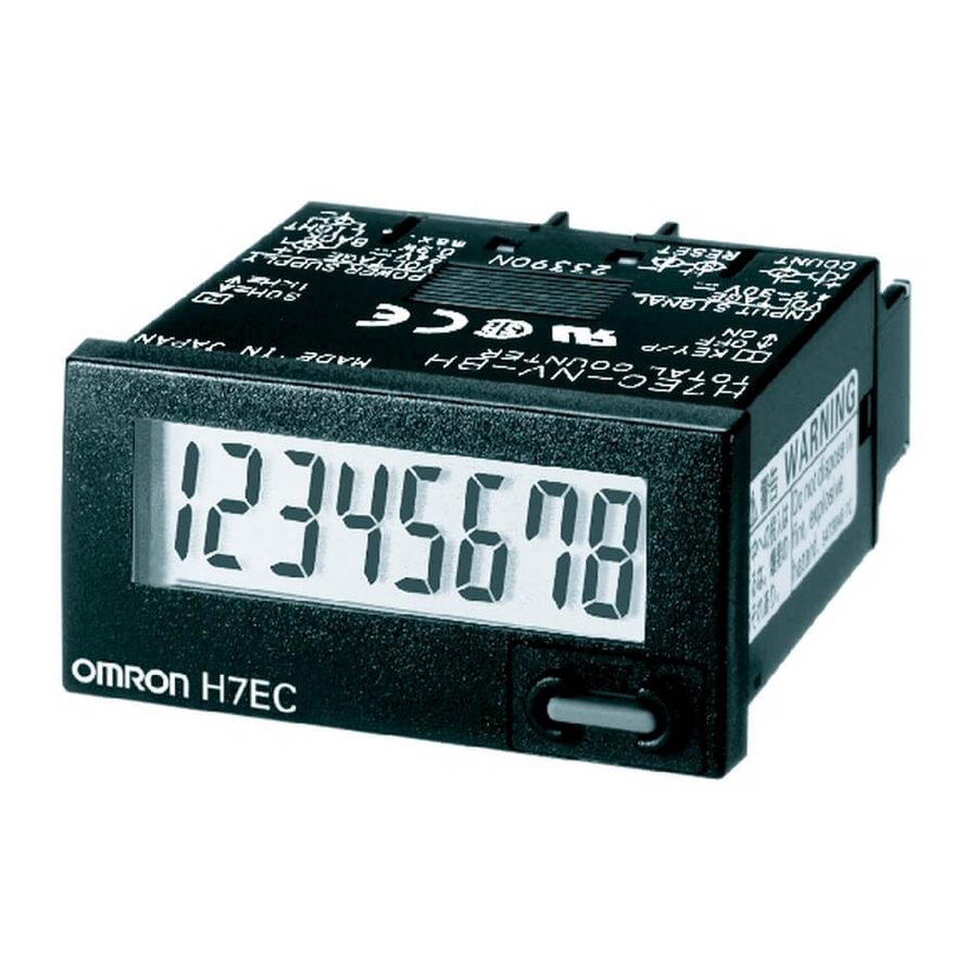
Self-powered Totalizer
H7E
Compact Economical Totalizer with High Visibility
Available with Backlit LCD Display
• Large display with 8.6-mm character height.
• Includes new models with backlight for improved visibility in dimly lit places. (Requires 24-VDC power supply.)
• Black and light-gray cases now available.
• PNP/NPN universal DC voltage input types now available.
• Battery is replaceable for Totalizer reuse and conservation of the environment.
• Key-protect switch to prevent faulty reset key operation.
• Dual operation mode.
• Front face compatible with NEMA4/IP66.
• Short body, all models have a depth of 48.5 mm.
• Finger protection terminal block conforms to VDE0106 Part100.
• Conforms to UL, CSA, and CE marking.
Conforms to EN61010-1 (pollution degree 2/overvoltage category III.)
• Conforms to EMC standards and EN61326, thus allowing use in residential, commercial and light- and heavy-industry environ-
ments.
• Six-language instruction manual provided.
• PCB-mounting models available. (Requires 3-V power supply.)
■ Broad Line-up of the H7E Series
H7EC
Total Counter
8-digit
Self-powered Totalizers
H7EC.....................................................................................................................
H7ET .....................................................................................................................
H7ER.....................................................................................................................
H7E@-N@P ...........................................................................................................
Common to All Totalizers
Accessories ...........................................................................................................
Precautions ...........................................................................................................
H7E
H7ET
Time Counter
999999.9h/
3999d23.9h
999h59min59s/
9999h59.9min
Contents
RC
H7ER
Tachometer
-1
1,000 s
with
1 pulse/rev. encoder
-1
1,000.0 s
with
10 pulse/rev. encoder
-1
1,000 min
with
60 pulse/rev. encoder
-1
10,000 min
with
60 pulse/rev. encoder
-1
1,000.0 min
with
600 pulse/rev. encoder
C-17
C-25
C-31
C-35
C-37
Self-powered Totalizer
H7E@-N@P
PCB-mounting Counter
Total Counter (8-digit)
Time Counter (999999.9h)
C-9
H7E
C-7
Advertisement
Table of Contents

Related Manuals for Omron H7E


Summary of Contents for Omron H7E
- Page 1 • Conforms to UL, CSA, and CE marking. Conforms to EN61010-1 (pollution degree 2/overvoltage category III.) • Conforms to EMC standards and EN61326, thus allowing use in residential, commercial and light- and heavy-industry environ- ments. • Six-language instruction manual provided.
- Page 2 Self-powered Totalizer...
- Page 3 Compact Flush Mounting Bracket (See note.) Y92F-35 Flush Mounting Adapter 26 mm 45.3 mm Y92F-75 27.5 mm 52.5 mm Y92F-76 24.8 mm 48.8 mm Y92F-77B Note: The New H7E models are supplied with a Y92F-34 Mounting Bracket. H7EC Self-powered Total Counter...
-
Page 4: Specifications
Count input PNP/NPN universal DC voltage in- AC/DC multi-voltage input No-voltage input Display 7-segment LCD with or without backlight, zero suppression (character height: 8.6 mm) (see note 2) Max. counting speed 30 Hz/1 kHz 20 Hz 30 Hz/1 kHz Case color... - Page 5 Static immunity 8 kV (malfunction) Vibration resistance Malfunction: 0.15-mm single amplitude at 10 to 55 Hz for 10 min each in 3 directions Destruction: 0.375-mm single amplitude at 10 to 55 Hz for 2 hrs each in 3 directions Shock resistance...
- Page 6 Open collector of an or Open collector of an NPN transistor NPN transistor Note: 1. Terminals 2 and 4 (input circuit and reset circuit) are func- tionally isolated. 2. Select input transistors according to the following: Dielectric strength of the collector 50 V Leakage current <...
- Page 7 0.5 V because the current flowing from terminals 1 or 3 is small thus allowing easy connection. 2. Select input transistors according to the following: Note: 1. Terminals 2 and 4 (input circuit and reset circuit) are Dielectric strength of the collector 50 V functionally isolated.
-
Page 8: Operating Modes
Front panel Bottom view Concave Front panel (default setting) side 30 Hz Concave side (default setting) Concave side 1 kHz Concave Terminal block side Terminal block Note: Perform switch setting before mounting to a control panel. H7EC C-14 Self-powered Total Counter... - Page 9 The appropriate thickness of the panel is 1 to 5 mm. Note: A Compact Flush Mounting Bracket (Y92F-35) can also be used. Refer to Accessories for details. H7EC C-15 Self-powered Total Counter...
- Page 10 H7EC C-16 Self-powered Total Counter...
- Page 11 Compact Flush Mounting Bracket (See note.) Y92F-35 Flush Mounting Adapter 26 mm 45.3 mm Y92F-75 27.5 mm 52.5 mm Y92F-76 24.8 mm 48.8 mm Y92F-77B Note: The New H7E models are supplied with a Y92F-34 Mounting Bracket. H7ET C-17 Self-powered Time Counter...
- Page 12 Flush mounting External connections Screw terminals Reset External/Manual reset Display 7-segment LCD with or without backlight, zero suppression (character height: 8.6 mm) (see note 1) Number of digits Time range 0.0h to 999999.9h 0.0h to 3999d23.9h 0s to 999h59min59s 0.0min to 9999h59.9min...
- Page 13 Static immunity 8 kV (malfunction) Vibration resistance Malfunction: 0.15-mm single amplitude at 10 to 55 Hz for 10 min each in 3 directions Destruction: 0.375-mm single amplitude at 10 to 55 Hz for 2 hrs each in 3 directions Shock resistance...
- Page 14 Open collector of an or Open collector of an NPN transistor NPN transistor Note: 1. Terminals 2 and 4 (input circuit and reset circuit) are func- tionally isolated. 2. Select input transistors according to the following: Dielectric strength of the collector 50 V Leakage current <...
- Page 15 Sensors or Photoelectric Sensors becomes less than 0.5 V because the current flowing from termi- nals 1 or 3 is as small as approx. 10 A, thus allow- ing easy connection. Note: 1. Terminals 2 and 4 (input circuit and reset circuit) are 2.
- Page 16 0s to 999h59min59s Concave 0.0h to 3999d23.9h side (default setting) Concave side Terminal block 0.0h to 999999.9h Concave 0.0min to 9999h59.9min (default setting) side Terminal block Note: Perform switch setting before mounting to a control panel. H7ET C-22 Self-powered Time Counter...
- Page 17 The appropriate thickness of the panel is 1 to 5 mm. Note: A Compact Flush Mounting Bracket (Y92F-35) can also be used. Refer to Accessories for details. H7ET C-23 Self-powered Time Counter...
- Page 18 H7ET C-24 Self-powered Time Counter...
- Page 19 Compact Flush Mounting Bracket (See note.) Y92F-35 Flush Mounting Adapter 26 mm 45.3 mm Y92F-75 27.5 mm 52.5 mm Y92F-76 24.8 mm 48.8 mm Y92F-77B Note: The New H7E models are supplied with a Y92F-34 Mounting Bracket. H7ER C-25 Self-powered Tachometer...
- Page 20 Mounting method Flush mounting External connections Screw terminals, Wire-wrap Terminals (see note 3) Display 7-segment LCD with or without backlight, zero suppression (character height: 8.6 mm) (see note 4) Number of digits Count input PNP/NPN universal DC No-voltage input PNP/NPN universal DC voltage input voltage input Max.
- Page 21 Static immunity 8 kV (malfunction) Vibration resistance Malfunction: 0.15-mm single amplitude at 10 to 55 Hz for 10 min each in 3 directions Destruction: 0.375-mm single amplitude at 10 to 55 Hz for 2 hrs each in 3 directions Shock resistance...
- Page 22 H7ER Tachometer Note: Select input transistors according to the following: Dielectric strength of the collector 50 V Leakage current < 100 A (1 A for no-voltage input model) PNP/NPN Universal DC Voltage Input Models With Backlight No-voltage Input Model Transistor Input...
- Page 23 10 pulse/rev. Terminal block 60 pulse/rev. "min " or "rpm" 1000 min H7ER-N-@ No setting is required H7ER-NV-@@ 1 pulse/rev. 1000 s "s " or "rps" Note: Perform switch setting before mounting to a control panel. H7ER C-29 Self-powered Tachometer...
- Page 24 The appropriate thickness of the panel is 1 to 5 mm. Note: A Compact Flush Mounting Bracket (Y92F-35) can also be used. Refer to Accessories for details. H7ER C-30 Self-powered Tachometer...
- Page 25 PCB-mounting Counters H7E@-N@P • Dedicated for use on PCB. • Total Counters and Time Counter available. Model Number Structure ■ Model Number Legend 1. Function Total Counter Time Counter 2. Max. Counting Speed for H7EC Models None: 1 kHz 30 Hz Ordering Information ■...
- Page 26 Static immunity 8 kV (malfunction) Vibration resistance Malfunction:0.15-mm single amplitude at 10 to 55 Hz for 10 min each in 3 directions Destruction:0.375-mm single amplitude at 10 to 55 Hz for 2 hrs each in 3 directions Shock resistance Malfunction:200 m/s...
-
Page 27: Battery Connections
■ Connections Power Supply and Battery Connections Battery Connections C is a film capacitor, of about 0.1 F, and is intended to absorb noise induced by the power lines. 3-V battery Keep the wiring between the H7E@-N@P and R or C as short as possible (within 50 mm). - Page 28 Collector breakdown voltage 50 V Leakage current < 1 A Use a diode (D) having a forward voltage as small as possible (0.1 V When the H7EC-NP is used, relay chattering may be counted. Use max. at I of 20 A).
- Page 29 ■ New H7E (Except for PCB-mounting Counter) The New H7E models are supplied with a mounting bracket (Y92F-34) and nut. Additionally, the Y92F-75/-76/-77B Flush Mounting Adapters shown here allow the New H7E models to be fitted to existing panel cutouts.
- Page 30 Y92S-37 Wire-wrap Terminal (Set of Two Terminals) 44.8 Wire-wrap terminal 1 mm) 48.5 17.1 When using the Wire-wrap Terminal, be sure to use the correct wires Wire Sleeve Wrapped state and peripheral devices. (The correct wires, bits and sleeves are AWG22 Normal shown in the table on the right.)
-
Page 31: Before Use
1 or 2 will be formed when the device is turned OFF. As a Remove the insulation sheet and press the Reset Key on the front result, the H7E may be reset or count by one. -
Page 32: Battery Replacement
No-voltage Input Models Tachometer • Do not impose voltage on the Counter if the Counter is a model that operates with no-voltage input, otherwise the internal circuit of the A unit label has been packed with the Counter. Use in accordance Counter may be damaged. - Page 33 240 VAC. Others If the indicator keeps flickering or is OFF, the internal battery may be close to the end of its service life. In such a case, it is suggested that the battery be replaced. ■ PCB-mounting Counter...
-
Page 34: General Information
10 . tion between the primary and the secondary circuit and having out- put voltage of 30 V rms max. and 42.4 V peak max. or 60 VDC max. Since the Counter is not flux-tight, do not use flux when soldering.
Need help?
Do you have a question about the H7E and is the answer not in the manual?
Questions and answers