Omron H8PS Manual
Cam positioner
Hide thumbs
Also See for H8PS:
- Operation manual (138 pages) ,
- Manual (19 pages) ,
- Instruction manual (2 pages)
Table of Contents
Advertisement
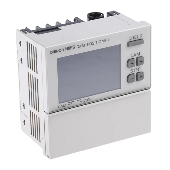
Cam Positioner
H8PS
Please read and understand this catalog before purchasing the
products. Please consult your OMRON representative if you have any
questions or comments. Refer to Warranty and Application
Considerations (page 32), and Safety Precautions (pages 17 and 18).
This Compact Cam Positioner, Popular for
It's Ease-of-use, Now Comes with Even
Better Functions.
• Compact 8-, 16-, and 32-output Models available that are 1/4-
DIN size at 96 x 96 mm.
• High-speed operation at 1,600 r/min and high-precision settings
to 0.5 ensure widespread application.
• Highly visible display with backlit negative transmissive LCD.
• Advance angle compensation function to compensate for output
delays.
• Bank function for multi-product production (8 banks).
(H8PS-16@/-32@ models.)
Features
Models with 8, 16, or 32 Outputs
The lineup includes Models with 32 outputs in a compact 1/4-DIN
size. Using the optional Parallel Input Adapter (Y92C-30) enables
expanding to up to 64 outputs for one encoder to support anything
from a simple positioning application to a large-scale system.
8-output Models
16-output Models 32-output Models
96 mm
96 mm
Simple Programming
The programming method is designed based on a one key-one
action concept for settings that could not be simpler. Both initial
settings and factory adjustments are effort-free.
Large, Backlit Negative LCDs
Large LCDs, red for the process value and green for set values, show
a wealth of operation information, making operating status visible at
a glance.
High Speed Up To 1,600 r/min
High Precision Up To 0.5 (at 720 Resolution)
High-speed, high-precision applications can be easily handled and
productivity increased.
Bank Function for Multi-product Production
Up to eight different programs can be registered in advance to
enable fast and easy switching between products (16/32-output
Models only).
USB Communications for Easy Setting from
a Computer
Optional Support Software can be used to enable programming from
a personal computer via USB communications. Programs can be
easily copied, saved, printed, and much more.
Speed Display and Speed Alarm Output
Both the speed (rotations/minutes) and present angular position can
be displayed at the same time. Alarm outputs can be produced for
both upper and lower speed limits.
1
2
7
RUN
Present angular
position
Speed
Upper limit
CAM
STEP
Lower limit
Switchable
Upper limit
alarm output
1
2
7
Lower limit
RUN
alarm output
Speed
Present angular
position
CAM
STEP
Advance Angle Compensation Function to
Compensate for Output Delays
The advance angle compensation (ADV) function automatically
advances the ON/OFF angle of outputs in proportion to machine
(encoder) speed to compensate for the delay in timing of ON/OFF
operation. ADV values can be set individually for 7 cam outputs.
Cam program settings
At high-speed (400 r/min)
Pulse Output for Timing Control
The number of pulses per rotation and the pulse output start angle
can be set to enable operations like adjusting timing with a PLC or
outputting to a rotation meter.
Pulse output
Cam Positioner
Speed
100
180
8 compensation
92
172
PLC
Rotation meter
H8PS
1
Advertisement
Table of Contents

Subscribe to Our Youtube Channel
Related Manuals for Omron H8PS


Summary of Contents for Omron H8PS
- Page 1 Large, Backlit Negative LCDs The advance angle compensation (ADV) function automatically Large LCDs, red for the process value and green for set values, show advances the ON/OFF angle of outputs in proportion to machine a wealth of operation information, making operating status visible at (encoder) speed to compensate for the delay in timing of ON/OFF a glance.
-
Page 2: List Of Models
Y92A-96N Track Mounting Base Y92F-91 Mounting Track 50 cm 7.3 mm (l PFP-50N 7.3 mm (l PFP-100N 16 mm (l PFP-100N2 End Plate PFP-M Spacer PFP-S Note: Ask your OMRON representative about the availability of non-standard lengths. H8PS Cam Positioner... -
Page 3: Specifications
Input type No voltage inputs: ON impedance:1 k max. (Leakage current: approx. 2 mA at 0 ON residual voltage: 2 V max., OFF impedance: 100 k min., Applied voltage: 30 VDC max. Minimum input signal width: 20 ms Outputs Cam outputs... - Page 4 Note: 1. Cam output precision, however, is 2 max. for Encoder with 256 resolution (P/R). 2. Although 32-output Models can have 10 steps set for any one output, there must be no more than 160 steps total set for all cam outputs.
-
Page 5: Functions
Automatically advances the ON/OFF angle of cam outputs in proportion to machine (encoder) speed to (ADV) function compensate for the delay in timing of ON/OFF operation. ADV values can be set individually for 7 cam outputs. Speed alarm output A specified cam output can be used as an Encoder speed alarm output. - Page 6 NPN Output, Encoder Flush Mounting Flush Mounting H8PS-8@ H8PS-16@/-32@ 24 VDC 6 7 8 9 10 11 12 13 Alignment markings 9 10 11 12 13 (Rear view) (Rear view) 1 2 3 4 5 Alignment markings 1 2 3 4 5 6 7 8...
- Page 7 Output Cable Connections (16-/32-output Models Only) Flush Mounting Models Surface Mounting Models Output Connector 1 (CN1) Output Connector 1 (CN1) Output Connector 2 (CN2) (See note.) Output Connector 2 (CN2) (See note.) (Bottom view) (Bottom view) Output Connector Output signals...
- Page 8 2. Y92S-41-200 Discrete Wire Output Cable (Order Separately) Connections Output Cable 1 Wiring Table H8PS-16@/-32@ Outputs Cable Marks Marking Outputs Cable Marks Marking color color color color Y92S-41-200 Discrete Wire ■ ■ Cam 1 Orange Black Cam 9 Orange Output Cable (Order Separately) ■...
-
Page 9: Input Connections
■ Input Connections Only the Encoder inputs are connected with 8-output Models. The inputs are no-voltage (short-circuit or open) inputs. No-voltage Inputs Contact Input Voltage-output sensors can also be connected. Open Collector Connection Examples PLC, sensor, Sensor, etc. etc. H8PS-16@... -
Page 10: Program Examples
89 and OFF at 44 in the diagram. (See note 2.) Note: The entire cam program can be changed at one time with 16- and 32-output Models with the bank function (banks 0 to 7). For details on the procedure for switching banks, refer to page 28. -
Page 11: Displays
Displays units for the angle or the speed displayed on main display. indication (11) Unit indication (4) Rotation display (12) Red Lit while using an Encoder with a resolution of 256 if 256 display is monitor selected. (12) 256 indication (13) Green Displays units for the angle or the speed displayed on sub-display. -
Page 12: Main Unit
Dimensions Note: All units are in millimeters unless otherwise indicated. ■ Main Unit Cam Positioners Flush Mounting Models Panel Cutout 15.2 21.6 M3.5 terminal screw (according to DIN 43700) H8PS-8B@ (8-output Models) +0.8 (14.6) 52.9 +0.8 Note: Mounting panel thickness must be 1 to 91.8... - Page 13 M4 nut (included) M4 screw (included) Y92C-30 Two, 4.3 dia. holes From the Dedicated Absolute Encoder Use the cable marked with a triangle when connecting only one H8PS Cam Positioner to the Parallel Input Adapter. 1,030 40.4 8.5 dia. 17 dia.
-
Page 14: Usb Cable
The Y96A-96N conforms to IP66 and 115.6 29.4 NEMA4 (for indoor use) standards for waterproofing. The operating environment may cause the waterproof packing to deteriorate, shrink, or harden. Therefore, it is recommended that the packing be replaced regularly. DIN Track Mounting Base Protective Cover... -
Page 15: Ratings And Characteristics
Rise and fall times of 1.0 s max. (control output voltage: 16 V; load 1.0 s max. (control output voltage: 5 V; load resistance: 1 k ; output cord: 2 m max.) output resistance: 1 k ; output cord: 2 m max.) Starting torque 0.98 m N·m max. - Page 16 (depth: 5) 120 0.1 Note: Order the E69-C08B Coupling separately. Round, shielded vinyl-insulated cord with 12 cores ( oil-resistant ) (external dia.: 6, cross-sectional area: 0.2 mm , insulation: 1.1 mm dia.), standard length: 1 m or 2 m E6F-AG5C-C...
-
Page 17: Mounting Procedure
Rotary Encoder is mounted with screws. E69-C10B 0.44 N·m • Do not pull wires with a force greater than 29.4 N while the Rotary Encoder is secured and wired. Be sure to turn Connect the power and I/O lines. -
Page 18: Environmental Precautions
• Store the H8PS within specified ratings. If the H8PS has been For 16- and 32-output Models, leave the protective label stored at temperatures 10 C or lower, let it stand for 3 hours or attached to the H8PS when wiring. Removing the label longer at room temperature before turning ON the power supply. - Page 19 225 ms max. Cam outputs Output OFF Output possible Output OFF RUN output Refer to the following manual for precautions in using the Cam Positioner and other information required for operation: H8PS Cam Positioner Operation Manual (Cat. No. Z199) H8PS Cam Positioner...
-
Page 20: Operating Procedures
➾ For details, refer to page 26 Advanced Functions. function Programming Cams (Programming Mode) There are three methods that can be used to set or change ON/OFF angles (i.e., cam programming). Setting ON/OFF Angles Using the ANGLE Keys (Manual Mode) -
Page 21: Setting The Origin
Setting Resolution and Rotation Setting the Origin Direction The origin of the Cam Positioner is set to match the origin of the machine (Encoder). The same origin is used for all banks. One of three resolutions can be selected for the Encoder connected (The bank function is supported only for 16-/32-output models.) -
Page 22: Setting On/Off Angles In Manual Mode
Cam Positioner. ON/OFF angles can be set based on actual machine (Encoder) operation. Example: Setting Step 1 of Cam No. 2 to Turn ON at 28 and Turn OFF at 51 Example: Setting the ON/OFF Angles by Teaching Step 2 of Cam No. - Page 23 If the timing is not correct, change the ON/OFF angle settings. The settings can be changed in Test Mode. Note: 1. Outputs will turn ON and OFF in Test Mode. Confirm system safety before switching to Test Mode. 2. With 16-/32-output model, be sure to turn ON the start input.
- Page 24 Key can be pressed to check the ON/OFF angle CHECK Speed (r/min) on main display settings in order for all steps starting from cam 1. If there is no key operation for 10 s or longer during the checking operation, the previous display will be resumed.
-
Page 25: Clearing Settings
Clearing Individual Steps, Cams, and Banks The all clear function can be used to delete all cam programs, the ON/OFF angle settings can be deleted by step, by cam, or by bank. If settings for advance angle compensation function, and all other settings are deleted by cam, the settings for the advance angle settings. -
Page 26: Mode Transitions
■ Advanced Functions Set the advanced functions as required to perform more advanced operation. Outlines of the advanced functions are provided on the following pages. For details, refer to the Operation Manual (Cat. No. Z199). Mode Transitions The values in parentheses are the default settings. - Page 27 ADV settings speed 0 to 3 256/360 1,600r/min 800r/min 4 to 7 256/360 1,200r/min 600r/min Note: Even if the ADV value is set to 0°, the cam must be included in the number of cams with ADV settings. H8PS Cam Positioner...
- Page 28 Lower Limit Alarm Output The speed alarm outputs are assigned to cam outputs as shown in the following table. The speed alarms are set to “- - -” for the default 0 10 settings, i.e., the normal cam outputs are enabled. If a speed alarm is Output start angle set to any value but “- - -”, the normal cam output for the...
- Page 29 Step Number Limit (f5) Bank Functions (f7/f8/f9) With the H8PS, up to 10 steps can be set to turn the output ON/OFF The bank function is supported by 16-/32-output models. Banks 10 times for each cam. The number of steps that can be set,...
- Page 30 The following methods can be used to switch the bank: the bank Programs can be copied between banks. This function is convenient inputs on the terminal block or the BANK Key on the front of the Cam to copy a program to a different bank when only some of the ON/OFF angle settings need to be changed.
-
Page 31: Self Diagnostic Function
■ Self Diagnostic Function The following displays will appear on the main display if an error occurs. If an error occurs, all outputs (including cam, pulse, and run outputs) will be turned OFF. Display Meaning Recovery method Origin designation data error Press the CLEAR Key for at least 3 s. - Page 32 CONTRACT, WARRANTY, NEGLIGENCE, OR STRICT LIABILITY. In no event shall the responsibility of OMRON for any act exceed the individual price of the product on which liability is asserted. IN NO EVENT SHALL OMRON BE RESPONSIBLE FOR WARRANTY, REPAIR, OR OTHER CLAIMS REGARDING THE...
Need help?
Do you have a question about the H8PS and is the answer not in the manual?
Questions and answers