Table of Contents
Advertisement
Quick Links
Model 5265MGSA
Mechanical Gel Strength Tester
Operation Manual
Rev D – February 2024
P/N: 5265MGSA-1050
(Original Instructions)
S/N _____________
2001 N. Indianwood Ave.
Broken Arrow, Oklahoma 74012 U.S.A.
Tel: 918-250-7200 Fax: 918-459-0165
E-mail: chandler.sales@ametek.com
Web: www.chandlereng.com
Advertisement
Table of Contents

Related Manuals for Ametek Chandler Engineering 5265MGSA


Summary of Contents for Ametek Chandler Engineering 5265MGSA
- Page 1 Model 5265MGSA Mechanical Gel Strength Tester Operation Manual Rev D – February 2024 P/N: 5265MGSA-1050 (Original Instructions) S/N _____________ 2001 N. Indianwood Ave. Broken Arrow, Oklahoma 74012 U.S.A. Tel: 918-250-7200 Fax: 918-459-0165 E-mail: chandler.sales@ametek.com Web: www.chandlereng.com...
- Page 2 This publication contains the following trademarks and/or registered trademarks: AMETEK, CHANDLER ENGINEERING. These trademarks or registered trademarks and stylized logos are all owned by AMETEK, Inc. All other company, product and service names and logos are trademarks or service marks of their...
-
Page 3: Table Of Contents
TABLE OF CONTENTS Table of Contents General Information ..............P-1 Purpose and Use..........................P-1 Description of Instrument ....................... P-1 Specifications ..........................P-2 Safety Requirements ........................P-3 Symbols Used on Equipment ......................P-4 Features and Benefits ........................P-5 Where to find help .......................... P-5 Section 1 –... - Page 4 TABLE OF CONTENTS Recovering from Set Cement ......................5-4 Configuring the Eurotherm Controller ................... 5-5 Change Temperature Units ......................5-5 Change the Temperature Offset ....................5-5 Load PID Values depending on Instrument ................. 5-6 Validating Motor Speed ........................5-7 Validating Load Cell Linearity ....................... 5-7 Maintenance Schedule ........................
-
Page 5: General Information
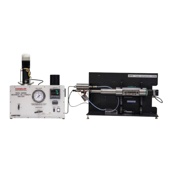
PREFACE General Information Figure 1 - Model 5265MGSA System Purpose and Use The Model 5265MGSA Gel Strength Analyzer is used to determine the gel strength of well cement slurries under HP/HT conditions in accordance with applicable API recommended practices. The system includes the 5265MGSA and a Quizix Q5120 pump used to accurately control sample pressure. -
Page 6: Specifications
PREFACE Specifications Operating Condition: Voltage: 208-240VAC Current: Frequency: 50 / 60 Hz, 1 Phase Overvoltage Condition: Category 2 Insulation Rating: Class 1 Fuse: 250 VAC, 10A, 5 x 20mm Working Pressure: 20000 psi, 138 MPa (1379 bar) Burst Pressure: 22500 psi (1551 bar) 450˚F (232˚C) Maximum Temperature: 34˚F (1˚C) -
Page 7: Safety Requirements
PREFACE Safety Requirements READ BEFORE ATTEMPTING OPERATION OF THE INSTRUMENT The Chandler Engineering Model 5265MGSA Gel Strength Analyzer is designed with operator safety in mind. Any instrument that is capable of high temperatures and pressures should always be operated with CAUTION. -
Page 8: Symbols Used On Equipment
PREFACE Symbols Used on Equipment Symbol Meaning Protective Conductor Terminal Caution, risk of electric shock. Equipment may be powered by multiple sources. Disconnect (Lock- out) all services before servicing. Caution, hot surface. Do NOT touch. Allow to cool before servicing. On (Power) Off (Power) Warning, Read... -
Page 9: Features And Benefits
• Stepper motor subsystem with built-in motor speed validation feature Where to find help In the event of problems, the local sales representatives will be able to help or the personnel at Chandler Engineering can be contacted. • Telephone: 918-250-7200 • FAX: 918-459-0165 • E-mail: chandler.sales@ametek.com • Website: www.chandlereng.com... - Page 10 PREFACE This page is intentionally left blank.
-
Page 11: Section 1 - Installation
SECTION 1 – INSTALLATION Section 1 – Installation Unpacking the Instrument Remove the instrument from the packing crate carefully. The unit comes fully equipped with all the necessary components and any spare parts that were ordered with the unit. Ensure that no parts or tools are lost when discarding the packing materials. - Page 12 1- 2 SECTION 1 - INSTALLATION This page is intentionally left blank.
-
Page 13: Section 2 - Software Configuration
SECTION 2 – SOFTWARE CONFIGURATION Section 2 – Software Configuration Configure 5270 Data Acquisition and Control Software version 2.10.3 or later per the following. The instrument can be configured to use either ModbusTCP (Ethernet) or ModbusRTU (Serial) I/O Connections. NOTE: These instructions assume that the operator has a working knowledge of the 5270 DACS Software. - Page 14 SECTION 2 – SOFTWARE CONFIGURATION 4. Configure the instrument as shown below. Figure 2 – Ethernet Instrument Configuration The “Temperature” Input Signal is not shown above: • Type: Input Signal • I/O Connection: TCP201 • Address: 2:1f NOTES: • 5270 will complain that the “Motor Speed” and “Motor Speed – Conditioning” are using the same address.
-
Page 15: Serial Communication
SECTION 2 – SOFTWARE CONFIGURATION Serial Communication The Motor uses an Ethernet interface. When communicating with the instrument via serial, the motherboard is a serial-to-ethernet bridge to the motor. In this configuration, the Network Section 8 – Configuration of the motherboard and motor must be compatible. Refer to Network Configuration for more information. -
Page 16: Complete The Instrument Configuration
SECTION 2 – SOFTWARE CONFIGURATION The “Temperature” Input Signal is not shown above: • Type: Input Signal • I/O Connection: 5265MG • Address: 2:1f NOTES: • The “Motor Speed”, “Motor Speed – Conditioning” and “Motor Encoder” Input Signals along with the “Motor Speed” Analog Output use the “l” (lower case L) register type. -
Page 17: 5265Mg Schedules
SECTION 2 – SOFTWARE CONFIGURATION • “Temperature” and “Wall Temperature” Input Signals i. Raw and Calibrated units should match the units used by the Controller. ii. The Calibration for these signals should be the default (Slope: 1; Offset: 0). These signals are calibrated at the controller. -
Page 18: Understanding The Network Configuration
SECTION 2 – SOFTWARE CONFIGURATION Understanding The Network Configuration The IP Address is a unique address that identifies a device on the internet or local network. Each device must have its own IP address. In order for devices to communicate with each other, they must both be connected to the network and they must have IP addresses that are on the same subnet. -
Page 19: Motor
SECTION 2 – SOFTWARE CONFIGURATION Motor The Applied Motion Products Step-Servo Quick Tuner software is required. This software is available from the Applied Motion Products website. Download the “Step-Servo Quick Tuner” software; this is different from the “Quick Tuner” software. At the time of this writing, the software was available from the following URL: https://www.applied- motion.com/s/software/step-servo-quick-tuner... -
Page 20: Ultrasonic Motherboard
SECTION 2 – SOFTWARE CONFIGURATION The Motor has a “Recovery” IP Address. If a network connection is not available to the motor within 10 seconds after power up, the Recovery IP Address will be used. To force the motor to use the Recovery address: •... -
Page 21: Temperature Controller
SECTION 2 – SOFTWARE CONFIGURATION Temperature Controller The Temperature Controller can be configured with the Eurotherm iTools software. At the time of this writing, the iTools software was available for download from the following URL: https://www.eurotherm.com/download/eurotherm-itools-v9-84/. The temperature controller uses a special Cascade Control firmware. The IDM (Interface Descriptor Module that tells iTools about the controller) is required;... - Page 22 SECTION 2 – SOFTWARE CONFIGURATION 2-10 • Press the Up button to change F.COm to O.COm • Press the Scroll button to enter the Option Comms menu; “mAIN” appears on the top line. • Press the Up button to change “mAIN” to “Nwrk” •...
-
Page 23: Section 3 - Operating Instructions
SECTION 3 – OPERATING INSTRUCTIONS Section 3 – Operating Instructions Front Panel Controls The figure below shows the front panel and all of the associated controls. The description of each control will follow the figure. Figure 5 – Front Panel Controls Vessel Cooling Valve Used to control the flow of coolant into the heating/cooling jacket with water connected to COOLANT INLET port on the Right Rear Panel. - Page 24 SECTION 3 – OPERATING INSTRUCTIONS Over Temperature Controller Over Temperature protection. When the Temperature is below 475°F (246°C), “SAFE” is displayed. When the Temperature is higher, “FAIL” is displayed and the Heater is disabled. Heater Switch Used to turn the flow of current to the heater ON or OFF. Switch must be in the ON position during testing and should be in the OFF position as a safety precaution at other times.
- Page 25 SECTION 3 – OPERATING INSTRUCTIONS Program Status: Indicates the current Program Step: Indicates Ramp / Step Up Indicates Dwell (Flashing indicates Dwell End) Indicates Ramp / Step Down. Manual Mode: Indicates Manual Mode has been selected. In Manual Mode, the Raise and Lower buttons operate on the Output Power.
- Page 26 SECTION 3 – OPERATING INSTRUCTIONS Use the following procedure to define and run a program. These steps will program a Ramp to user-defined Temperature in a user-defined amount of time and then Dwell. This can also be done using the 5270 software. 1.
- Page 27 SECTION 3 – OPERATING INSTRUCTIONS Left Rear Panel The left rear panel contains all the connections for the cables that connect the autoclave to the processor. Ultrasonic Connector Not used on this instrument. Thermocouple The J-type thermocouple that is attached to the top plug must be plugged into this connector prior to the beginning of a test and any time that it is necessary for the temperature...
-
Page 28: Operational Guidelines
SECTION 3 – OPERATING INSTRUCTIONS Right Rear Panel The right rear panel contains all the connections for hydraulic and pneumatic utilities. Figure 8 – Right Rear Panel Air Inlet, Pump Water Drain/Inlet These connectors are used to connect the pneumatic and hydraulic utilities High Pressure Inlet (optional) This high-pressure connector exists so that pressure may be controlled with an alternate pressure control system. -
Page 29: Top Plug Disassembly / Assembly
SECTION 3 – OPERATING INSTRUCTIONS Top Plug Disassembly / Assembly 1. Pull the paddle shaft assembly from the plug. The bottom baffle is equipped with an o-ring used to retain the baffle within the plug. 2. Verify that the thermocouple port and fill ports are not filled with the cement and the thermocouple slides freely into the port. - Page 30 SECTION 3 – OPERATING INSTRUCTIONS Figure 10 - Paddle Shaft Assembly and Plug Assembly 6. Install the seal ring and o-ring on the top plug. Apply a thin coating of lithium grease (or other suitable lubricant) to the o-ring.
-
Page 31: Load Cell Installation / Removal
SECTION 3 – OPERATING INSTRUCTIONS Load Cell Installation / Removal Figure 11 – Load Cell Installation / Removal... -
Page 32: Load Cell Plug Installation / Removal
SECTION 3 – OPERATING INSTRUCTIONS 3-10 Load Cell Plug Installation / Removal Figure 12 – Load Cell Plug Installation / Removal Cable Connections There are 3 cables from the 5265MG Motor and Vessel Assembly: 1. 5265MX-0075 Load Transducer Assembly: connects to the “LOAD SENSOR” connector on the Rear Panel of the Instrument. -
Page 33: Starting A Test
SECTION 3 – OPERATING INSTRUCTIONS 3-11 Starting a Test 1. Using water and detergent, clean the pressure vessel, top plug and magnetic drive housing, bottom plug. 2. Insert the tapered sample sleeve into the vessel. This sleeve reduces the effort required to remove a sample at the end of a test. -
Page 34: Stopping A Test
SECTION 3 – OPERATING INSTRUCTIONS 3-12 Stopping a Test 1. When the test is complete, click the “Stop Test” in the toolbar. The following dialog is displayed. By default, the Temperature controller is checked but the Motor controller is not. Check the box next to “Motor Speed”... - Page 35 SECTION 3 – OPERATING INSTRUCTIONS 3-13 This page is intentionally left blank.
-
Page 37: Section 4 - Calibration
SECTION 4 – CALIBRATION Section 4 – Calibration The Model 5265MGSA requires periodic calibration of the load cell used to measure the torque on the paddle that is immersed in the cement sample. A calibration fixture and traceable mass are provided to create known torques on the motor carriage and a 2-point calibration is performed. - Page 38 SECTION 4 – CALIBRATION This page is intentionally left blank.
-
Page 39: Section 5 - Maintenance And Servicing
SECTION 5 – MAINTENANCE AND SERVICING Section 5 - Maintenance and Servicing Note: Always disconnect the power connection prior to service. Tools Required • 5/8-inch wrench (supplied with instrument) • Hex wrenches (supplied with instrument) • Spanner wrench (supplied with instrument) •... -
Page 40: Motor Housing Assembly / Disassembly
SECTION 5 – MAINTENANCE AND SERVICING Motor Housing Assembly / Disassembly Figure 14 – Reference 5265MG-0310 1. Install the housing retaining ring over the motor shaft. 2. Clean the motor support bearings of any grease and verify that they spin freely. 3. - Page 41 SECTION 5 – MAINTENANCE AND SERVICING 9. Place the external magnet assembly inside the support housing. Align the set screw with the keyway on the motor shaft. Do not tighten the set screw at this point. 10. Install the linear bearings (2) and the slide rod. Orient the slot in the rod upwards. Verify that the slide rod translates freely.
-
Page 42: Recovering From Set Cement
SECTION 5 – MAINTENANCE AND SERVICING Recovering from Set Cement The 5265MG is designed to minimize damage from an inadvertent circumstance where cement becomes solid. The top plug may be removed with the inner magnetic drive and paddle remaining in the solid cement. 1. -
Page 43: Configuring The Eurotherm Controller
SECTION 5 – MAINTENANCE AND SERVICING Configuring the Eurotherm Controller The controller contains many menus containing parameters that are not visible during normal use. A detailed description of each parameter is beyond the scope of this manual. Please refer to the controller manual for the details. During normal use, the controller provides access to the Level 1 menu. -
Page 44: Load Pid Values Depending On Instrument
SECTION 5 – MAINTENANCE AND SERVICING Load PID Values depending on Instrument To load the appropriate PID Tuning values for the currently configured instrument: 1. From the Home Screen, press the Scroll button. “LOAD” appears in the Middle Readout. 2. Press the Raise and Lower buttons to scroll through the available recipes (SGSA, mG and uCA). -
Page 45: Validating Motor Speed
SECTION 5 – MAINTENANCE AND SERVICING Validating Motor Speed The stepper motor used with the system rotates at accurate speeds. For motor speed validation, use the following procedures: At speeds above 10 rpm, a hand-held tachometer is used to validate the speeds. At speeds in the range 0.20 –... - Page 46 SECTION 5 – MAINTENANCE AND SERVICING This page is intentionally left blank.
-
Page 47: Section 6 - Troubleshooting Guide
SECTION 6 – TROUBLESHOOTING GUIDE Section 6 - Troubleshooting Guide The following table lists symptoms of several common problems, the possible cause of the problem, and the possible solution to the problem. PROBLEM SOLUTION Poor gel strength measurement Clean the motor support bearings until they spin freely. sensitivity Clean the bearing at the top of the magnet housing until it spins freely. - Page 48 SECTION 6 – TROUBLESHOOTING GUIDE This page is intentionally left blank...
-
Page 49: Section 7 - Replacement Parts List
SECTION 7 – REPLACEMENT PARTS LIST Section 7 – Replacement Parts List PART NUMBER DESCRIPTION 07-1540 ELEMENT ASSY,100 MICRON 80-0016 SEAL RING - CYLINDER 80-0021 THERMOCOUPLE, UCA 5265MX-0022 SHAFT, PADDLE 5265MX-0080 SLEEVE,STAND 5265MX-0102 SLURRY LEVEL GAUGE, 5265MG 5265MX-0108 PADDLE, 5265MX 8053-5265MG-E OVERTEMP,5265MG,F 8053-5265MG-M... - Page 50 SECTION 7 - REPLACEMENT PARTS LIST This page is intentionally left blank.
-
Page 51: Section 8 - Drawings And Schematics
SECTION 8 – DRAWINGS AND SCHEMATICS Section 8 – Drawings and Schematics PART NUMBER DESCRIPTION 5265MG-0310 5265MG ASSEMBLY 5265MG-BASE-0008 DIAGRAM,TUBING 5265MGSA-FP FRONT PANEL LAYOUT 5265MX-0009 PROC,CALIBRATION,5265MG 5265MX-0122 PROC,VALIDATION,MOTOR SPEED,5270 5265MX-0056 CALIBRATOR ASSEMBLY,5265MX X265-WD DIAGRAM,WIRING,USONIC DRAWER... - Page 52 DESCRIPTION DATE APPROVED ISSUED 03/28/23 ECN T9624; H-10-125 WAS H-10-112; ADDED 5/25/2023 H-10-002 ECN T9653; CREATED 5265MG-0210 7/25/2023 PRESSURE VESSEL ASSY ECN T9794; CHANGE HIGH PRESSURE TUBE 1/21/2024 VERIFY THAT THE MOTOR PIVOTS FREELY ON AXIS WITH MINIMAL OFF-AXIS MOVEMENT ITEM PART NUMBER DESCRIPTION...
- Page 53 CHANDLER ENGINEERING BREAK EDGES, DEBURR DRAWN: JJM 5/10/2023 THIS DOCUMENT AND THE DRAWINGS AND TECHNICAL DATA CONTAINED HEREON ARE THE UON DIMS ARE IN INCHES MFG: JDS 5/15/2023 PROPERTY OF CHANDLER ENGINEERING COMPANY LLC. REPRODUCTION OR DISSEMINATION IN ANY 1 PLC 0.030 2 PLC 0.010...
- Page 54 6 2X MAY NEED TO LINEAR BEARINGS SHORTEN SET SCREW MUST SLIDE FREELY TO ALLOW BEARING INTO BORES TO FREELY SLIDE INTO PLACE NOTE: REMOVE GREASE FROM BEARINGS AND ADD 3 DROPS OF P-1765 MINERAL OIL. BEARINGS MUST SPIN FREELY 25 2X 24 2X ITEM...
- Page 56 DESCRIPTION DATE APPROVED ISSUED 2024-02-15 80-0021 THERMOCOUPLE C11293 GAUGE 5265MG-0310 ASSEMBLY 9050-5265MG-E ( F) 9050-5265MG-M ( C) 8053-5265MG-E ( F) 8053-5265MG-M ( C) C12161 HEATER SWITCH C11271 VALVES C16690 POWER SWITCH P-2193 VALVE CHANDLER ENGINEERING BREAK EDGES, DEBURR DRAWN: JJM 2024-02-15 THIS DOCUMENT AND THE DRAWINGS AND TECHNICAL DATA CONTAINED HEREON ARE THE...
- Page 57 Part Number: 5265MX-0009 Page 1 of 3 TITLE: PROC,CALIBRATION,5265MG REF. NEXT ASSY: MODEL 5265MG GEL STRENGTH TESTER Revision Date Revised By Description 08/14/19 ECN T8631 UPDATED PROCEDURE The Model 5265MG requires periodic calibration of the load cell used to measure the torque on the paddle that is immersed in the cement sample.
- Page 58 Part Number: 5265MX-0009 Page 2 of 3 TITLE: PROC,CALIBRATION,5265MG REF. NEXT ASSY: MODEL 5265MG GEL STRENGTH TESTER 9. Using the following table of masses and calibration values, individually enter the low and high Scaled Values followed by selecting Add Sample. ...
- Page 59 Part Number: 5265MX-0009 Page 3 of 3 TITLE: PROC,CALIBRATION,5265MG REF. NEXT ASSY: MODEL 5265MG GEL STRENGTH TESTER...
- Page 60 Part Number: 5265MX-0122 Page 1 of 7 TITLE: PROC, VALIDATION, MOTOR SPEED, 5270 REF. NEXT ASSY: MODEL 5265MG GEL STRENGTH TESTER Revision Date Revised By Description 3/30/16 ISSUED To validate the stepper motor speed of the 5265MG in the range 0.20° - 2.0°/min, use the following procedure: 1.
- Page 61 Part Number: 5265MX-0122 Page 2 of 7 TITLE: PROC, VALIDATION, MOTOR SPEED, 5270 REF. NEXT ASSY: MODEL 5265MG GEL STRENGTH TESTER 4. Select “OK”. 5. If the Motor Speed Validation schedule is not already configured, Use Tools – Options – New to create a new Controller Schedule.
- Page 62 Part Number: 5265MX-0122 Page 3 of 7 TITLE: PROC, VALIDATION, MOTOR SPEED, 5270 REF. NEXT ASSY: MODEL 5265MG GEL STRENGTH TESTER Figure 1 - Define the Temperature Units...
- Page 63 Part Number: 5265MX-0122 Page 4 of 7 TITLE: PROC, VALIDATION, MOTOR SPEED, 5270 REF. NEXT ASSY: MODEL 5265MG GEL STRENGTH TESTER Figure 2 - Define the Pressure Units...
- Page 64 Part Number: 5265MX-0122 Page 5 of 7 TITLE: PROC, VALIDATION, MOTOR SPEED, 5270 REF. NEXT ASSY: MODEL 5265MG GEL STRENGTH TESTER Figure 3 - Adding a Motor Schedule Figure 4 - Motor Speed Schedule Creation. Note that other speeds in the range 0.20° - 2.0°/min may be used instead 6.
- Page 65 Part Number: 5265MX-0122 Page 6 of 7 TITLE: PROC, VALIDATION, MOTOR SPEED, 5270 REF. NEXT ASSY: MODEL 5265MG GEL STRENGTH TESTER 7. Select the 5265MG instrument to start a 5265MG test. 8. Select the Motor Speed Validation controller schedule. 9. Select “Start Test”. Assign a file name when prompted. 10.
- Page 66 Part Number: 5265MX-0122 Page 7 of 7 TITLE: PROC, VALIDATION, MOTOR SPEED, 5270 REF. NEXT ASSY: MODEL 5265MG GEL STRENGTH TESTER 12. Subtract the two Motor Encoder readings, multiply by 360 and divide by 51200. The result is the measured speed in °/min.
- Page 67 DESCRIPTION DATE APPROVED NOTES: ECN T7159; DELETE C16183 1000 WEIGHT, VERIFY THAT PULLEY SPINS AND SLIDES FREELY ON DOWEL PIN. ADD P-1351-CERT AND P-1352-CERT 3/29/2016 APPLY LOCTITE (C07246) TO DOWEL PIN, PRESS INTO PLACE, DO NOT ALLOW LOCTITE TO CONTACT BEARING. WEIGHT AND HANGER.
- Page 73 cut out postcards on dotted lines Please Send Us Your Comments on This Manual Model Number ____________________________ Serial Number __________________________ Printing Date of this manual (from the Title Page) ______________ Please circle a response for each of the following statements. Use: (1)= Strongly agree (2) =Agree (3) =Neutral, no opinion (4) =Disagree (5) =Strongly disagree a) The manual is well organized.
- Page 74 cut out postcards on dotted lines...
- Page 75 4903 W. Sam Houston Parkway, N., Suite A-400, Houston, TX 77041 2001 North Indianwood Avenue, Broken Arrow, OK 74012 Tel: +1 713-466-4900 Fax: +1 713-849-1924 Tel: +1 918-250-7200 Fax: +1 918-459-0165 e-mail: chandler.sales@ametek.com www.chandlereng.com Printed in the U.S.A. © 2008, by AMETEK, Inc. All rights reserved. XM808PDF (360000)
Need help?
Do you have a question about the Chandler Engineering 5265MGSA and is the answer not in the manual?
Questions and answers