Table of Contents
Advertisement
Advertisement
Table of Contents

Related Manuals for Ametek MiniFlash FP Vision


Summary of Contents for Ametek MiniFlash FP Vision
- Page 1 FLASHPOINT TESTER MINIFLASH FP(H) Vision OPERATION MANUAL M-V1.01 SW-V4.00...
-
Page 4: Table Of Contents
TABLE OF CONTENTS GENERAL SAFETY SUMMARY ........................1 SYMBOLS ..............................2 GENERAL INFORMATION .......................... 4 Measuring standards ........................... 6 3.1.1 Standard method ASTM D6450 ...................... 6 3.1.2 Standard method ASTM D7094 ...................... 6 MINIFLASH versions ..........................7 3.2.1 FP VISION – Standard Temperature Version Type 440 ..............7 3.2.2 FPH VISION - High temperature version Type 441 ................ - Page 5 9.2.7 Stand by ............................46 RESULTS ............................. 47 10.1 Result List............................47 10.2 Details for combustion analysis ......................48 STATUS ............................... 49 11.1 Statuspage ............................49 SETTINGS ............................50 12.1 Settings Menu ............................ 50 MAINTENANCE ............................. 51 12.2 NETWORK Connection ........................51 12.2.1 Requirements ..........................
-
Page 7: General Safety Summary
Under normal circumstances they should always be used in a fume-hood away from possible sources of ignition. For further information read the safety data sheet of the substance. © AMETEK, Inc. -
Page 8: Symbols
SYMBOLS Instrument symbols Attention – Dangerous high voltage Protective Ground connection Take care when touching – Hot surface No mains connection. Instrument is turned off Mains connected. Instrument is turned on © AMETEK, Inc. - Page 9 Attention! Corrosive and caustic substance! Attention! Flammable substance! < Attention! Lethal voltage! When opening the instrument and violation of safety rules, there is a risk of injury and death. Before opening the instrument disconnect unit from mains! Attention! High voltage! © AMETEK, Inc.
-
Page 10: General Information
The way of heating the sample cup from the top cover prevents condensation of a high volatile part of the sample on the oven surface. No condensation of high volatile substances due to heating the sample from the top. © AMETEK, Inc. - Page 11 The surface from the oven outside the heat shield should be clean to give a good heat contact to the sample cup. This surface should be cleaned regularly with tissue paper and some solvent. © AMETEK, Inc.
-
Page 12: Measuring Standards
ASTM D7094 repeatability and reproducibility was calculated including lube oils. For more information on round robin tests and the standard methods ASTM D6450 and ASTM D7094 feel free to ask the local representative or directly Grabner Instruments. © AMETEK, Inc. -
Page 13: Miniflash Versions
However, this high temperature range can only be achieved with a very special technical arrangement. Note: Flashpoint standards usually require starting at least 18°C below the expected flashpoint for standard compliant flashpoint measurements. © AMETEK, Inc. -
Page 14: Measuring Method
The MINIFLASH FP(H) Vision is protected by following patents: WO 2011140576 US 8950934 EP 2569617 AT 509743 You can search for the patents here: Espacenet http://worldwide.espacenet.com United States Patent and Trademark Office http://patft.uspto.gov/ © AMETEK, Inc. -
Page 15: Features Miniflash Fp(H) Vision
W x H x D = 253 x 368 x 277 mm W x H x D = 10 x 14.5 x 10.9 inches Operating Temperature: 0°C to 50°C (32°F to 122°F) Environmental Specifications Operational humidity: ≤ 90% RH non condensing Weight FP(H) VISION 11 kg (26 pounds) © AMETEK, Inc. -
Page 16: Unpacking
ASTM D 6450 1 Sample cup standard 7 mL FL-M041021.01 (Aluminum, Nickel plated) for the measurement acc. to ASTM D 7094 1 Sample cup carrier FPV-SUB022 1 Stirring magnet MAGNET-D3X13 Removing nipper FPV-SUB034 Service dish assy FPV-SUB037 © AMETEK, Inc. - Page 17 NK-498/13-SVT3X18AWG (left EU or right US) (115V) NK-H05VVF3G0.75/2 (230V) 2 x 1m 6/4 hoses for water SCHL-PFAM 6/4 cooling, Max. filling pressure: 7.5 bar!!!! FP Vision only 1 Operation manual 1 Test certificate 1 Shipping Case SHIPPING-CASE-BIG © AMETEK, Inc.
- Page 18 Sample cup 4 mL (stainless steel) for the FL-M920206.05-SS measurement of aggressive samples acc. to ASTM D 6450 Sample cup 7 mL (stainless steel) for the FL-M041021.01-SS measurement of aggressive samples acc. to ASTM D 7094 BIOHIT Pipette SPRITZE-BIOHIT1 © AMETEK, Inc.
-
Page 19: Miniflash Fp(H) Vision Front Panel
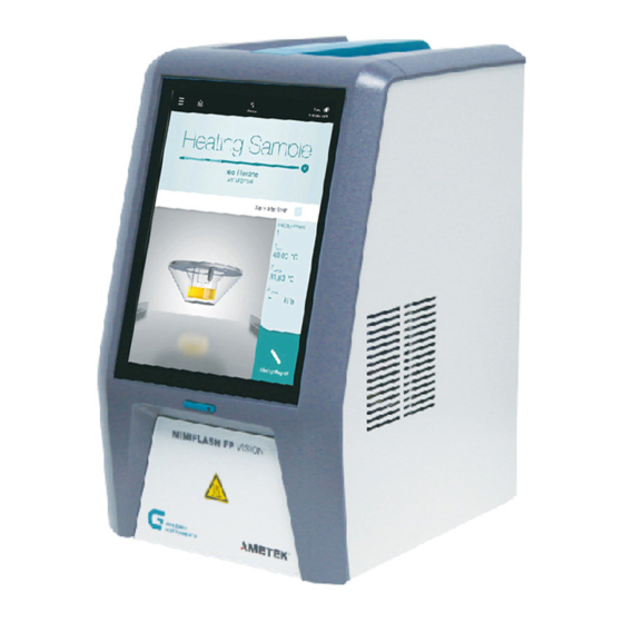
MINIFLASH FP(H) VISION OPERATION MANUAL MINIFLASH FP(H) VISION front panel 10” Color Touch Screen Power Safety Cover Sample infeed © AMETEK, Inc. -
Page 20: Miniflash Fp(H) Vision Rear Panel
MINIFLASH FP(H) VISION rear panel 4x USB, LAN Interface, HDMI Network, PC, LIMS Power supply and main switch Water cooling Connection (FP Vision only!) Max. Pressure: 7.5 bar! © AMETEK, Inc. -
Page 21: Installation
On the rear panel of the instrument you find 4 USB connectors for a USB-sticks and USB-printers 5.3.4 Preinstalled Printer Drivers Hewlett Packard Series M530 is pre-installed on the device and the only tested printer. Other printers can be installed upon service request. © AMETEK, Inc. -
Page 22: Dc/Ac Power Converter Prowatt 300 Installation
The flashpoint tester can be used in the field particularly in mobile laboratories mounted on vibration lowered mounting plates. When used in mobile laboratories mains is available. If operated in the field with a car battery a power converter available for the analyzer can be used to power up the instrument. © AMETEK, Inc. - Page 23 MINIFLASH FP(H) VISION OPERATION MANUAL For more information of using the instrument with the car battery see chapter „DC/AC power converter” © AMETEK, Inc.
-
Page 24: User Management
Cockpit: Manage Flexibility Login / Logout Adjust Calibration Perform Measurements Adjust Device Configuration View Results Create, Collect and Distribute Data Basic Maintenance (Rinsing, IP Address, …) Handle User Management Basic Settings (Date, Time, …) Backup and Update © AMETEK, Inc. -
Page 25: End User License Agreement
Before first use you have to accept the End User License Agreement. Press >Accept> to complete the registration. Full information about the End User License Agreement (EULA) for the MINIVAP VP Vision can be reviewed, downloaded and printed here: http://www.grabner-instruments.com/legal/index.aspx © AMETEK, Inc. -
Page 26: Login
As labmanager you can setup multiple standard and advanced users accounts. It is only possible to log in to the shown users. In case other users are needed, please see the manual for the COCKPIT to add additional users to the device. © AMETEK, Inc. -
Page 27: Logout
MINIFLASH FP(H) VISION OPERATION MANUAL Logout Press the “Menu” button Press “Logout © AMETEK, Inc. -
Page 28: Quick Start Measurement
After first start of the device and the login as labmgr, Last Used Settings is selected. In the bottom section of the screen the last used template is loaded and displayed. To open the sample drawer, please press the eject button. © AMETEK, Inc. - Page 29 Sample name: here it is possible to enter a name or number for the sample which is to be tested. Please use the display keyboard to type in the desired sample name. As well an external keyboard or barcode reader can be used. © AMETEK, Inc.
- Page 30 Committee: with the committee section you can select the method for the sample test procedure. Available committees are ASTM, EN, IP, JIS, SHT/T, GB-T, Navy and Custom. Standard: with the standard selection you can select the following standards. © AMETEK, Inc.
- Page 31 Custom Type: with the menu you can select either REFILLING or NON REFILLING. REFILLING is for measurements according to standards and NON-REFILLING is for repeated measurements with the same sample, e.g. for test runs with pure components. © AMETEK, Inc.
- Page 32 NOTE: every measurement cycle is completed with the amount of cycles entered. Ti is the initial temperature starting point for the measurement cycle. According to ASTM standard D6450 and D7094, the start temperature must be 18 °C (64,4 °F) below the expected flashpoint. © AMETEK, Inc.
- Page 33 Every different adjustment for different samples can be saved as a new template on the unit with different names. This should allow the user to create own templates which can be overwritten and deleted from the unit. © AMETEK, Inc.
- Page 34 The sample name must be typed in before the measurement is started using the onscreen keyboard. Start measurement: With this button you start the measurement according to the previously selected settings. Then the measurement overview is shown. © AMETEK, Inc.
- Page 35 Once Ti is reached, the analyzer asks the operator to insert the sample. Please confirm the opening of the drawer. After confirmation, the drawer is opened and ready that the operator puts the sample cup on the drawer. © AMETEK, Inc.
- Page 36 After the sample is inserted, please The moving stick shows that the stirrer is activated During an ignition, the sample cup is blue colored. Only in case a flashpoint is detected, or no flash occurred until Tf is © AMETEK, Inc.
- Page 37 On the result page the measured flash point temperature is indicated on top. Below the user can select show all parameters of the measurement by pressing “+”. The bottom part shows the pressure graph of the whole measurement cycle. © AMETEK, Inc.
- Page 38 It is as well possible to review the whole results stored on the unit by pressing the result overview. The results overview is showing all measurement results stored on the unit. By selecting one or more results, those © AMETEK, Inc.
- Page 39 MINIFLASH FP(H) VISION OPERATION MANUAL can be deleted, printed and exported. There is as well a search function available to search through the results. There are as well the options to filter and sort the results. © AMETEK, Inc.
-
Page 40: Create A Custom Measurement
In case no flashpoint is detected, the measurement is stopped with the result No flash. Ti-T … this is the parameter to cool the sample in case the measurement has to start below ambient temperature. © AMETEK, Inc. - Page 41 Precaution interval … interval for safety ignition when the sample is colder than Ti. The measurement is stopped in case a flashpoint is detected during the heating to Ti. Stirrer … The speed of the magnetic stirrer can be adjusted between 50-450rpm © AMETEK, Inc.
- Page 42 In the method ASTM D6450 + Screen D6450 the air ventilation is defined with 1,5ml. In the free programmable method, the air ventilation can be freely adjusted. In preconfigured methods ASTM D6450 and D7094, ignition interval, heat rate and air ventilation are predefined and cannot be changed. © AMETEK, Inc.
-
Page 43: Fuel Dilution Curve
The relationship between flash point and fuel dilution is non-linear and has to be evaluated experimentally. 8.1.1 Fixed installed dilution curve (Navy JP6 and F75) Following curves are available: Tflash[°F] Dilution[%] 259,1 263,3 273,5 287,8 297,7 310,1 330,5 366,7 Tflash[°F] Dilution[%] 310,6 313,9 317,7 322,0 327,0 333,1 340,7 350,8 365,5 392,2 © AMETEK, Inc. -
Page 44: Custom Fuel Dilution Curve
Shows that the sample (e.g. oil with Diesel) can be still used as a lubricant e.g.: in an engine. – between 2% to 5% from nominal value ● Shows that the sample (e.g. oil with Diesel) is not good for being used as a lubricant e.g.: in an engine. – above 5% from nominal value © AMETEK, Inc. -
Page 45: Methods
ASTM D6450 method can be used. To get the information at which temperature the flashpoint occurs the temperature range must be entered where the flashpoint is expected. © AMETEK, Inc. -
Page 46: Astm D93A / Iso 2719A Correlation Method (Pensky Martens Closed Cup)
Set the sample name, the initial temperature (expected flashpoint), the temperature range and the energy. Then use a cool 2 mL sample cup and start the test. Ignition steps are programmed and follow the ISO 3679 / 3680 correlation method. © AMETEK, Inc. -
Page 47: Astm D93B / Iso 2719B Correlation Method (Pensky Martens Closed Cup)
If no flashpoint appears at the first ignition at the limit of e.g.: 80°C (176°F) the sample is ok for our example and therefore “NO-FLASH”. If a flashpoint is detected, the true flashpoint is somewhere below the limit of 80°C (176°F) and therefore “FLASH”. © AMETEK, Inc. -
Page 48: Non-Refilling Option
(flashpoint at 76.1°C), whereas the second test already produces a 78.1°C result, as expected for pure dodecane. To select a batch run, please select “Non-Refilling” as option during the setup of the measurement. © AMETEK, Inc. -
Page 49: Start Temperature Adjustment (Ti-T)
For testing flashpoint according to standards, the pressure threshold for flashpoint tests must be 20 kPa. If you are using the standard methods ASTM D6450 and ASTM D7094, the pressure threshold is locked to 20 kPa and cannot be changed. © AMETEK, Inc. -
Page 50: Measuring
After this checks the oven temperature is raised with the programmed heating rate. When the sample has reached the starting temperature, the first ignition for a flash test is initiated and the pressure increase is monitored. If it is below the threshold the measurement is continued. © AMETEK, Inc. -
Page 51: Air Introduction Into The Measuring Chamber
After detection of a flash point or reaching the final temperature the measurement is stopped and the oven is cooled down fast to the starting temperature Ti. The sample cup is lowered automatically when the temperature of the oven is at Ti-(Ti-T). © AMETEK, Inc. -
Page 52: Stand By
9.2.7 Stand by The oven temperature is kept at the level of the starting temperature for further 30 minutes. If no measurement is started within these 30 minutes the temperature regulation of the oven is switched off. © AMETEK, Inc. -
Page 53: Results
The Result overview is listed in the Main Menu, during the measurement and after measurements are finished. The result list can be accessed by tapping the arrow button on the bottom right corner. Scroll through the result list by moving the results up and down with your finger. © AMETEK, Inc. -
Page 54: Details For Combustion Analysis
3 … Save all selected results to USB 4 … Select results 5 … Search a specific sample by name 6 … Delete selected results 10.2 Details for combustion analysis Please see the COCKPIT for combustion analysis © AMETEK, Inc. -
Page 55: Status
MINIFLASH FP(H) VISION OPERATION MANUAL 11 STATUS 11.1 Statuspage This page shows the status of the device. © AMETEK, Inc. -
Page 56: Settings
2 … Change date, time and time zone – press Set immediately after setting the date, time and time zone because the instrument will restart to activate the changes. 3 … Select time format 4 … Change units 5 … Select printer © AMETEK, Inc. -
Page 57: Maintenance
IP address field shows just an empty line 12.3 CONNECT to Grabner-Instruments This selection is to open the remote connection that Grabner Instruments service technicians can assist you directly on the device. © AMETEK, Inc. -
Page 58: Shut Down
13 SHUT DOWN To shut down the analyzer, please press the shutdown button in the menu section. ATTENTION: Prevent burning of the next user. Shut down the instrument only AFTER the sample cup has COOLED to ambient temperature. © AMETEK, Inc. -
Page 59: Cockpit Software
Once the update is finished, the Cockpit software will detect whether connected Vision instruments need to be updated. An <Update> tab will appear for instruments that require an update: Click on <Update> to update the Vision analyzer to the latest version. © AMETEK, Inc. -
Page 60: Preventive Maintenance
In order to get accurate ignitions for tests the arc pins must be cleaned regularly. Therefore use the brass brush to free the arc pins from soot or other residuals. When doing so take care not to bend the temperature sensor (2) or the arc pins (1). © AMETEK, Inc. -
Page 61: Clean Temperature Probe
Take care that cleaning agents are evaporated already prior filling with fresh sample. If cleaning of a sample cup is not done properly, wrong flashpoints are detected due to contaminations of previous tested samples. © AMETEK, Inc. -
Page 62: Error Messages And Troubleshooting
The lift is going down again. If this happens please check the position of the sample cup. If the sample cup is placed correctly and the lift still goes down several times, then the initial lift position needs to be recalibrated. Contact the local representative or Grabner Instruments directly. © AMETEK, Inc. -
Page 63: Sample Too Hot
> Ti) to allow a measurement according standard, the instrument Sample gives a warning as follows: Sample too hot If tests are done near or below environmental temperature, cool your sample cup prior filling the sample into the cup and use the cold-filling option. © AMETEK, Inc. -
Page 64: Missing Sample
The ceramic insulation of the arc pin in the oven seems to be broken. The insulation against the oven is not present anymore, thus the arc is deduced on the oven instead of the second arc pin. © AMETEK, Inc. -
Page 65: Pressure Detection Problems
Check if the sample temperature sensor is bent or broken. If the differences between sample temperature and oven temperature are too high (>7°C – cup filled with sample and in upper position) check the position of the sample temperature sensor. © AMETEK, Inc. -
Page 66: Other Errors
16.8 Other Errors For any other error message displayed on the device, please restart the analyzer. In case the restart does not solve the problem, please contact your nearest service partner or Grabner Instruments directly. Thank you. © AMETEK, Inc. -
Page 67: Ce Declaration
MINIFLASH FP(H) VISION OPERATION MANUAL 17 CE Declaration © AMETEK, Inc. -
Page 68: Customer Support And Information
Tel: +43 / 1 / 282 16 27-0 Fax: +43 / 1 / 282 16 27 300 E- Mail: grabner.office@ametek.com Internet: www.grabner-instruments.com For technical support, register and create at ticket online at: www.grabner-care.com Representatives and Distributors: www.grabner-instruments.com © AMETEK, Inc. - Page 69 MINIFLASH FP(H) VISION OPERATION MANUAL MINIFLASH FP(H) VISION MANUAL REVISION Version # Date Editor Changes 1.00 09/13/2019 Hadl First Version 1.01 01/29/2020 Hadl Update of max temp FPH Vision © AMETEK, Inc.
Need help?
Do you have a question about the MiniFlash FP Vision and is the answer not in the manual?
Questions and answers