
Subscribe to Our Youtube Channel
Related Manuals for Ametek CS2-225


Summary of Contents for Ametek CS2-225
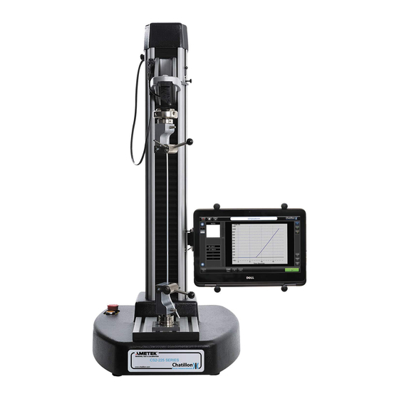
- Page 1 Part No. 01/5009 September 2017 CS2-225 & CS2-1100 Force Tester User Manual The CS manual is also available on the Ametektest website.
- Page 2 This instrument is warranted against defects in workmanship, material and design for one (1) year from the date of delivery to the extent that AMETEK will, at its sole option, repair or replace the instrument or any part thereof which is defective, provided, however, that this warranty shall not apply to instruments subjected to tampering or, abuse, or exposed to highly corrosive conditions.
- Page 3 CAUTION! HIGH FORCES ARE OFTEN INVOLVED WITH THE MATERIAL TESTING PROCESSES. The machine is powered by mains supply voltage The machine is a Class 1 product, which means it MUST be connected to a mains socket outlet with a PROTECTIVE EARTH CONNECTION Do not position the equipment so that it is difficult to operate the mains disconnect device (machine mains inlet socket) If the equipment is used in a manner not specified by the manufacturer, the protection provided by the...
- Page 4 Position the CS series force tester so that it is easy to access the mains power switch and mains power cord. Never use the CS series force tester in a manner not specified by AMETEK. Obey all warning labels on your CS series force tester.
-
Page 5: Table Of Contents
Table of Contents 1.0 Introduction............................9 1.1 SAFETY ......................................9 1.2 ELECTRICAL SAFETY .................................. 10 1.3 OPERATIONAL PRECAUTIONS ..............................10 2.0 Installation ............................. 11 2.1 UNPACKING ....................................11 2.2 SETTING UP YOUR FORCE TESTER ............................12 2.3 VOLTAGE SELECTION AND FUSES ............................13 2.4 CONTROL CONSOLE AND LOADCELL CABLES ........................ - Page 6 4.12 CHANGING OPERATOR ................................25 4.13 JOG PANEL ....................................26 4.14 TURNING OFF THE CS2 FORCE TESTER ..........................27 5.0 Preparing the Force Tester......................28 5.1 FITTING A LOADCELL .................................. 28 5.2 T SLOT TABLE ....................................29 5.3 LOWER ANCHOR PIN ................................... 30 5.4 LIMIT STOPS ....................................
- Page 7 9.11 EDITING OR DELETING A STAGE ............................57 9.12 ADDING A STAGE ..................................57 9.13 TEST RESULTS SCREEN ................................58 9.14 ARCHIVE AND EXPORT SETTINGS SCREEN ........................63 9.15 DISPLAYING THE TEST GRAPH SCREEN ..........................64 10.0 Using the Force Tester ........................ 65 10.1 PERFORMING A TEST ................................
- Page 8 17.0 Communications ........................102 17.1 CONFIGURING THE COMMUNICATIONS ..........................102 17.2 USING THE COMMUNICATIONS ............................. 103 18.0 Technical Specifications ......................104 18.1 TECHNICAL SPECIFICATION CS2-225 ........................... 104 18.2 TECHNICAL SPECIFICATION CS2-1100..........................104 19.0 Overall Dimensions ........................105 21.0 Spare Parts Kits ......................... 106...
-
Page 9: Introduction
A transparent splinter shield is available as an option for the CS2-225 (P/N 01/3909) and CS2-1100 (P/N 01/3910) to enclose the test sample (see section 14). A shield should be fitted if there is any danger of samples shattering during the test. -
Page 10: Electrical Safety
1.2 ELECTRICAL SAFETY The CS2 Force Tester has been designed to meet the requirements of BS EN 61010-1:2010 safety requirements for electrical equipment for measurement, control and laboratory use. 2. The User Manual contains some information and warnings, which must be followed by the user to ensure safe operation and to keep the machine in safe condition. -
Page 11: Installation
All operators must receive adequate training in basic operation before being allowed to use the machine. Additional copies of this manual are available from AMETEK Inc. Operators must ensure that the Emergency Stop Button is never obstructed. -
Page 12: Setting Up Your Force Tester
2.2 SETTING UP YOUR FORCE TESTER The CS2 Force Tester is a heavy item and great care should be taken in choosing the location where it is to be installed. Ensure the bench is capable of remaining firm and stable, withstanding the combined weight of the machine and any accessories supplied. -
Page 13: Voltage Selection And Fuses
WARNING: Replace the fuses with the exact same type and rating as the ones supplied by factory. Do not replace with higher or lower rated fuses. Fuse Ratings and Part Numbers Model Fuse Rating Part Number Type CS2-225 - 3.15A SPK/LS/0011/A T3A15H250 115VAC CS2-225 - 3.15A... -
Page 14: Control Console And Loadcell Cables
2.4 CONTROL CONSOLE AND LOADCELL CABLES NOTE: To maintain EMC compatibility, only connection leads supplied by CHATILLON should be used to connect the control console and Loadcell. 2.5 MOUNTING THE LAPTOP CONSOLE The Laptop console is fitted with a rear mounted ball joint adapter. The force tester is supplied with another ball joint adapter fitted on the right-hand side of the vertical column. -
Page 15: Connecting The Laptop Console Power Cable
2.6 CONNECTING THE LAPTOP CONSOLE POWER CABLE The Laptop console is powered using the supplied "plug top" power supply. Plug this into the mains outlet on the rear of the machine then connect the circular power supply plug to the DC input socket on the lower left-hand side of the Laptop console. -
Page 16: Emergency Stop Switch
The safeline button is mounted on the left-hand side of the frame and is initially illuminated to indicate that there is no power to the crosshead motor circuit and the crosshead cannot move. The safeline circuit must be activated before the force tester can be used. Pressing the safeline button will turn the light off to indicate that the force tester is now ready for use. -
Page 17: Initial Configuration
3.0 Initial Configuration 3.1 GENERAL The Laptop console uses Windows 10 Pro for the Operating System together with a dedicated force tester program. Both items need to be configured before the system is fully operational and all features become available. 3.2 INITIAL LOG-IN Switch the Force Tester on and press the Laptop Power ON button located in the top right-hand corner of the Tablet then wait for the CS2 "LOGIN"... -
Page 18: Languages
(note the underscore) and this must be stored in the "C:\Program Files (x86)\AMETEK, Inc\Chatillon CS Control Software\Assets" folder. When viewing the control panel, click on the "Up" arrow on the Toolbar to display the "C:\" drive then move around the drive to the "C:\Documents and Settings\MyUser\Assets" folder. -
Page 19: Dedicated Program Configuration
Calibration Date and Console Software Version. NOTE: The date and time is setup in the Windows Control panel while logged in as administrator. It is recommended to contact your AMETEK representative if your Tester needs to be calibrated CS User Manual 19... -
Page 20: User Settings
The “Load Cell Calibration” button does have a factory Password. The access to the menu is restricted to calibration personnel. If you need access, please contact the Customer Care Dept. at AMETEK. If no user restrictions or user identification are required, then no further action is necessary. The Force Tester can be used, after it has been switched on, by pressing the "LOGIN"... - Page 21 The Force Tester can now only be used after a user has logged on using a defined User Name and Password. If a Supervisor password has been created, please ensure that this password is remembered, or securely stored for future reference, because AMETEK is not responsible for lost passwords. CS User Manual 21...
-
Page 22: Setting Default Units
4.3 SETTING DEFAULT UNITS The "Global Default Units" are displayed on the right-hand side of the screen. Whenever a new test is performed, all test results will be reported in these units. Note that the result units can always be changed whenever the test results are displayed. -
Page 23: Grip Protection
Force Tester must be re-zeroed whenever grips are changed or removed before trying to re-position the crosshead. The maximum pinch load that can be set is 200N or 40lbf. However, AMETEK recommends that the pinch load is not set above 50N or 10lbf. -
Page 24: Slow Jog Speed
Slow Jog Speed setting. The slow speed is to allow the crosshead to be accurately positioned ready for fitting a sample so should be set to a reasonable value, e.g. 100mm/min or 4in/min. The “Maximum” Slow Jog Speed is limited to 635mm/min (25in/min) for a CS2-225 and 508mm/min (20in/min) for a CS2-1100. -
Page 25: Returning To The Home Screen
4.11 RETURNING TO THE HOME SCREEN Press the "HOME" Icon at the top left of the screen to display the "HOME" screen. 4.12 CHANGING OPERATOR If 2 or more operators have been defined during the installation, then the "Active" operator can log-off by pressing on the "CHANGE USER"... -
Page 26: Jog Panel
4.13 JOG PANEL The crosshead (moving arm) can be moved up and down to position it ready for testing. This is achieved by using the Jog Control Panel, which is displayed by pressing the "Jog Panel" Icon in the bottom left-hand corner of the screen. -
Page 27: Turning Off The Cs2 Force Tester
4.14 TURNING OFF THE CS2 FORCE TESTER To turn OFF the CS Series test machine go to the Main screen and follow the screens below for “User & Supervisor”. The CS2 tablet should always be shut down FIRST before turning OFF the main power switch. Then the power switch in the rear of the tester may be turned OFF. -
Page 28: Preparing The Force Tester
5.0 Preparing the Force Tester 5.1 FITTING A LOADCELL Place the Loadcell fixing screw through the top of the hole in the crosshead and carefully offer up the Loadcell with the connecting lead facing inwards under the crosshead. Screw the fixing screw into the Loadcell, taking care to ensure that the locating dowel on top of the Loadcell, locates in the hole in the moving crosshead. -
Page 29: T Slot Table
5.2 T SLOT TABLE The base of the force tester is fitted with a "T" slot table together with a universal mounting plate to allow a range of fixtures to be used. The mounting plate is secured to the "T" slot table using 2 fixing bolts and this can be positioned as required by loosening the bolts using the 5mm hexagonal key provided. -
Page 30: Lower Anchor Pin
5.3 LOWER ANCHOR PIN The force tester is supplied with a Lower Anchor Pin assembly which is fitted to the "T" slot table using two 5mm countersunk bolts. If the Lower Anchor Pin is to be used, it should be adjusted so that it is accurately aligned with the pin on the attached Loadcell. -
Page 31: Limit Stops
5.4 LIMIT STOPS The CS2 Force Tester is fitted with two mechanically activated limit stops. These can be used as extra protection to stop Loadcells, grips or fixtures coming into contact. The upper one can be used to back up the test upper limit. -
Page 32: Defining A Test
6.0 Defining a Test The Force Tester can be used in a number of different ways: - 1 Perform a Single Stage Test without Saving Data (Quick Test) 2 Create a Compression Test File, Perform Tests and Save Data 3 Create a Tension Test File, Perform Tests and Save Data 4 Create a Multi-Action Test File, Perform Tests and Save Data 5 Load a Previously Defined Test, Perform Tests and Save Data 6.1 NOTES... -
Page 33: Single Stage Test Without Saving Data
7.0 Single Stage Test Without Saving Data This "Quick Test" feature is provided to allow a quick test to be performed on a sample, in either Tension or Compression mode, where the test results and graphical data are not required to be stored in a test file. However, the test data can be exported and/or printed if required. - Page 34 The first configuration screen displays the "Basic Settings" for the test and includes "Direction", "Distance Compensation", "Preload", "Data Rate", "Auto Zero" and Auto Return". Select the required "Direction" using the controls on the left-hand side of the screen. Note that Compression means move the crosshead downwards during the test and Tension means move the crosshead upwards during the test.
-
Page 35: Test Limits Screen (See Paragraph 8.5 Test Limits Screen)
When performing very long tests, it is recommended that the data rate is reduced to use less memory and a suitable data rate is 10Hz. When performing very short tests, the data rate can be increased up to 1000Hz, if required, noting that more memory will be used during the test because more data is being stored. -
Page 36: Export Settings Screen
7.3 EXPORT SETTINGS SCREEN After the Limits have been set, press on the "NEXT" button at the bottom of the screen to display the "EXPORT SETTINGS" screen. If NO results are to be exported or printed, press on the "FINISH" button at the right of the screen to display the "QUICK TEST -TEST GRAPH"... -
Page 37: Defining A Compression Or Tension Test
8.0 Defining a Compression or Tension Test The "Quick Test" feature shown in section 7 does not store any test data in a test file so these tests cannot be analyzed at a later date. Therefore, 3 other options are provided to create test files that are used to store test results and graphical data and these files can be analyzed at a later date. - Page 38 A test is created by moving through a sequence of configuration screens which is intuitive and easy to use. Each configuration screen has a "HELP (?)" button at the bottom of the screen and pressing this “?” button will display the relevant "HELP" screen. Each help screen only displays the information for the appropriate configuration screen for ease of use.
- Page 39 For information, the test files are stored in the control console in a folder called "C:\Documents and Settings\MyUser". The operator does not have to use Windows to select, use or store these test files because these functions are built into the Dedicated Test Program. A small picture can be displayed in the Test Selector area (see later) to assist the operator when selecting a test file.
-
Page 40: Test Limits Screen
Select the required "Auto Zero" action using the controls on the right-hand side of the screen. When Auto Zero is selected, the force tester distance and force will be set to Zero before every test. However, please note that this feature can cause incorrect force readings especially if wedge grips are being used. - Page 41 Decide how the test is to end. There are 2 methods provided to stop a test and these can be used together. 1 Stop at a "Limit", which can either be a force or a distance 2 Stop when the sample "Breaks", i.e. the force drops in a defined way a Stop at a Force Value To stop the test at a force value, select the "LOAD"...
- Page 42 The ramping is to be ON when it is critical to end the test at a precise Load or Distance limit. Ramping is ON by default for every new test created. It is vital to have Ramping ON when Testing hard materials and/or when the compression test ends very close to any hard surfaces to assure that the CS2 Tester doesn’t overshoot the limit.
-
Page 43: Question Screen
The Percentage Drop detector will detect a break if the force falls to a specified percentage of the maximum load so is suitable for samples that crack or tear so that the load falls too slowly for the Sharp Break Detector to operate correctly. -
Page 44: Test Results Screen
8.7 TEST RESULTS SCREEN After the question has been set, press on the "NEXT" button at the bottom of the screen to display the "TEST RESULTS" screen. Press on the top left drop-down button labeled "NONE" to display a drop-down list containing "NONE", "OVERALL RESULTS", optionally "QUESTION STAGE"... - Page 45 If the "OVERALL RESULTS" option is selected using the top left drop-down button, then pressing on the drop- down button underneath it will display a second drop-down list. This list provides test results that are based upon general test information and contains "NONE", "TIME DURATION", "OVERALL PASS/FAIL RESULT", "RECORD NUMBER", "DATE"...
-
Page 46: Archive And Export Settings Screen
Note that only 5 results can be displayed on the graph screen and any remaining checkboxes will be disabled after 5 results have been selected. If a "TENSION STAGE" result is selected, the controls to the right-hand side of the result selectors are now enabled and these can be used to provide Pass/Fail criteria for the selected test result. -
Page 47: Displaying The Test Graph Screen
To export the data to the specified CSV file, enable the CSV option. To create a pdf document, select the Graph option. To Auto Export a CSV or Graph, select the “Auto-Export” box. To Export Results in ASCII format through the RS232 port select the “RS232” box. To exclude result headers from the data output select “Do not export result headers”... -
Page 48: Defining A Multi-Action Test
9.0 Defining a Multi-Action Test The "Compression" or "Tension" tests shown in section 8 are used to store test results and graphical data and these files can be analyzed at a later date. However, these tests only provide a single test action and do not provide a "Sample Height" feature so there is another option to create a Multi-Action (Multi-Stage) test file that is used to store test results and graphical data and this file can be analyzed at a later date. - Page 49 The first configuration screen displays the "Basic Settings" for the test and includes "Test Name", "Test Image", "Height Mode", "Distance Compensation", "Preload", "Data Rate", "Auto Zero" and Auto Return". Press on the "Test Name" entry field to display the alphanumeric keypad then enter the required name for the test file.
-
Page 50: Select Next Stage Screen
When performing very long tests, it is recommended that the data rate is reduced to use less memory and a suitable data rate is 10Hz. When performing very short tests, the data rate can be increased up to 1000Hz, if required, noting that more memory will be used during the test because more data is being stored. -
Page 51: Create A Tension Stage
The Icon at the left-hand side of the screen shown above shows "Height Mode" (Red dot at the bottom of the vertical line). Note that the "CYCLE" and "HOLD" buttons are not enabled until either a "TENSION" Stage or a "COMPRESSION"... - Page 52 d Stop at a Force Value or when the Sample Breaks To stop the test at a force value OR if the sample breaks, select and define the "LOAD" option as shown above, then define the "Break" operation using the controls on the right-hand side of the screen. (See later). e Stop at a Distance Value or when the Sample Breaks To stop the test at a distance value OR if the sample breaks, select and define the "DISTANCE"...
-
Page 53: Create A Cycle Test
9.5 CREATE A CYCLE TEST A "Simple" cycle test consists of 2 stages that are repeated for a set number of times. The first action could be (say) move upwards by 10 inches and the second action could be (say) move downwards to the initial starting position. -
Page 54: Create A Compression Stage
Assume that the test action (e.g. move up by 10 inches then move back to the start of test position) takes 18 seconds for each cycle. The time at the end of cycle 1 is 18 seconds, end of cycle 2 is 36 seconds, end of cycle 3 is 54 seconds and end of cycle 4 is 72 seconds. -
Page 55: Create A Hold Load Stage
9.7 CREATE A HOLD LOAD STAGE A "Hold Load" Stage is used to maintain a "Constant Load" on the sample for a specified time period and is commonly used to measure "Sample Creep" so is also called a CREEP Test. The Force Tester is set to a special mode to move the crosshead as necessary to maintain the specified load for the required time period. -
Page 56: Create A Zero Stage
9.9 CREATE A ZERO STAGE The Load and Distance values may be automatically zeroed at the beginning of the test by using the Auto Zero feature. However, these values may also be zeroed during a test by selecting a Zero Stage. Press on the "ZEROING"... -
Page 57: Editing Or Deleting A Stage
9.11 EDITING OR DELETING A STAGE A previously defined stage can be edited or deleted as required. Select the required stage by pressing on it in the "STAGE LIST" shown on the right-hand side of the screen, to enable the "EDIT" and "DELETE" buttons. Press the "EDIT"... -
Page 58: Test Results Screen
If the "HOLD" stage button is pressed, then a "HOLD" stage will be inserted between stages 2 and 3 so that the "CYCLE" stage now becomes stage 4. Note that the Cycle Loop "Bracket" now encloses stages 1 to 4. If another stage is required at the BOTTOM of the stage list and a stage is selected, press on the "EDIT"... - Page 59 If the "OVERALL RESULTS" option is selected using the top left drop-down button then pressing on the drop- down button underneath it will display a second drop-down list. This list provides test results that are based upon general test information and contains "NONE", "TIME DURATION", "OVERALL PASS/FAIL RESULT", "RECORD NUMBER", "DATE"...
- Page 60 If the "QUESTION STAGE" option is selected using the top left drop-down button then pressing on the second drop-down button will display a second drop down list. This list provides test results that are based upon the question so only contains "ANSWER". If the "CYCLE STAGE"...
- Page 61 To set up a Custom Load Average result, select “Custom Load Average (CLA)”: Then press the “Configure” button and this screen will appear: Then enter in the Start and End Distance for the test and then press “OK” button. CS User Manual 61...
- Page 62 “Second Peak Load” captures the second highest load peak during a test Stage and “Distance Second Peak” captures the second highest distance peak during a test Stage The “Spring Rate” calculates the rate of Compression or Tension between 2 points in percentage or distance. To change the unit (which will be initially set to the "Default"...
-
Page 63: Archive And Export Settings Screen
9.14 ARCHIVE AND EXPORT SETTINGS SCREEN After the Test Results have been selected, press on the "NEXT" button at the bottom of the screen to display "ARCHIVE AND EXPORT SETTINGS" screen. If NO results are to be exported or printed, press on the "FINISH" button at the right of the screen to display the "TEST GRAPH"... -
Page 64: Displaying The Test Graph Screen
9.15 DISPLAYING THE TEST GRAPH SCREEN After the Archive and Export Settings have been set, press on the "FINISH" button at the bottom of the screen to display the "TEST GRAPH" screen. This screen has a title showing the previously entered test name. Please refer to section 10 for details regarding test samples. -
Page 65: Using The Force Tester
10.0 Using the Force Tester 10.1 PERFORMING A TEST A test can be performed whenever the "TEST GRAPH" screen is displayed. This screen will be displayed immediately after defining a new test or can be displayed by loading a saved test file - Please refer to section 11. - Page 66 When the crosshead is in a suitable position for testing, press the "Jog Panel" Icon again to close the Jog Control Panel. The test is started by pressing on the green "START TEST" button at the bottom right-hand side of the screen.
- Page 67 Please note that when an eye end and grip is fitted to the Loadcell, the "Load Bar" will indicate a small tensile load (bar above horizontal line) due to the weight of the grips or fixtures. Also note that the “Load Bar” does not reset to zero when the “ZERO”...
- Page 68 When the test has finished, the test graph is displayed in the "Graph Area" and the selected results are displayed in the "Test Results" area to the left of the graph as shown below. The picture above shows the default graph axes of Load / Time. Other axes of Distance / Time and Load / Distance are available and the graph will cycle through the available axes by repeatedly pressing the "CHANGE AXES"...
- Page 69 Pressing the "CHANGE AXES" button again changes the graph to show Load / Distance. The graph and measured results shown above are displayed using the previously defined default Load Axis Unit of "N" and the previously defined default Distance Axis Unit of "mm". The graph load axis and load results will cycle through the available Load Axis units by repeatedly pressing the "CHANGE FORCE UNITS"...
- Page 70 When this second test has finished, the new test graph is displayed in the "Graph Area" and the selected results are displayed in the "Test Results" area to the left of the graph. The left-hand vertical area of the screen now displays two buttons, marked "1" and "2", to show that 2 tests have been performed.
-
Page 71: Markers And Notes
10.2 MARKERS AND NOTES If the "Break Detector" is used and a "Break" is detected, then this is automatically marked on the graph as shown below: - A "Marker" can also be placed on the graph for any result by pressing on the required "Result" button to the left of the graph. - Page 72 To mark the "Load Peak" position, press on the "LP" button to the left of the graph. Note that the button is outlined in blue and the position is marked on the graph as "LP1" as shown below. To remove the marker, press on the "LP" button again. The blue outlining around the button is removed and the marker is also removed.
-
Page 73: Archiving, Exporting & Printing; Graphs, Data & Results
10.3 ARCHIVING, EXPORTING & PRINTING; GRAPHS, DATA & RESULTS At any time at the end of a test or tests, results can be archived by pressing the “ARCHIVE RESULTS button on the right-hand side of the screen”. The Raw Graph Data Points can be exported to a CSV file by pressing the “EXPORT DATA” button on the right-hand side of the screen. -
Page 74: Data Table And Statistics
10.4 DATA TABLE AND STATISTICS The "Graph" area normally displays the last test graph during the testing sequence but can also display a table of test results or the calculated test statistics by using the “VIEW” buttons on the right-hand side of the screen. A table of test results is displayed by pressing on the "DATA TABLE"... - Page 75 A table of test statistics is displayed by pressing on the "STATISTICS" button. The test statistics are shown above. The top left area shows the test status for every test. The test status is normally the pass/fail status and the example screen shows that 7 samples were tested and that 6 samples passed and 1 sample failed.
-
Page 76: Printing And Exporting Data Table And Statistics
The selected test in the previous table is excluded (removed) from the statistics as shown below. The top left area still shows that 7 samples were tested but now 6 samples passed and 1 sample was excluded. If the excluded sample is to be reused in the statistics, press on the required sample number then press on the yellow "X"... - Page 77 The “PRINT REPORT” button" creates a PDF document with the measured results as shown in the example printout below. This document is created "On Demand" and can be useful if printed documentation of the test results is required. Note that the document is stored in the folder specified on the "ARCHIVE AND EXPORT SETTINGS" screen during the test configuration except for the “PRINT REPORT”...
- Page 78 This data may be preceded by the Result Headers if selected during the test configuration. An example export is shown below: - Test Runs,11 Passed,11 Failed,0 Excluded,0 Result,Max,Min,Rng,Avg,Std Dv,COV Date (),,,,,,, Time (),,,,,,, Peak (N),85.10,11.57,73.53,29.98,23.08,77.01, Break (N),85.10,12.68,72.41,34.64,24.55,70.89, Run,Excluded,Date,Time,Peak (N),Break (N),Dist@P (mm),Dist@B (mm),Notes, 1,,12/11/12,12:26:08,51.43,51.43,46.99,46.99,, 2,,12/11/12,12:26:49,48.91,35.94,24.52,31.83,, 3,,12/11/12,12:28:09,44.66,30.14,21.65,26.72,,...
-
Page 79: Test Notes
10.6 TEST NOTES 1 If a percentage drop break detector is used to end the test, the Force at Break value is not a “True” break value but is the specified percentage of the maximum force value. 2 If a time duration result is requested, this may be slightly longer than the actual test time duration because of latency at the start of the test. - Page 80 A previously saved test file can be loaded by pressing on the large “LOAD A SAVED TEST FILE” Icon on the main screen or the small Icon at the top left of the screen. In both cases, the “TEST SELECTION” screen is displayed which shows all the test files present in the internal memory.
- Page 81 The tests can also be listed in 3 alternative orders of “Date”, “Run” and “Favorites”. The test files can be displayed in "REVERSE Date” order by pressing on the “DATE” button along the top of the screen. Note that the “Date” is the date that the test file was created. The newest test file is listed first then the other files are listed in descending order of date of creation.
-
Page 82: Favorites Feature
10.8 FAVORITES FEATURE The previous section showed that previously saved test file can be loaded by pressing on the large “LOAD A SAVED TEST FILE” Icon on the main screen or the small Icon at the top left of the screen. However, for ease of use, up to 10 Test Files can also be displayed directly on the main screen if they are marked as "Favorites". - Page 83 Note that the "HOME" screen now displays the "Favorite" files in the lower area. These files will open and display the "TEST GRAPH" screen ready for testing by pressing on the relevant Icon. Note that the CS Series only allows a maximum of 10 Favorite tests to be stored in memory. Home Screen for a Supervisor with Favorites Displayed Home Screen for a User with Favorites Displayed CS User Manual 83...
-
Page 84: Test File Maintenance
10.9 TEST FILE MAINTENANCE The test files are stored on the Hard Drive and all testing is performed using these files. The test setups may also be backed up or transferred to another CS Series Force Tester if required as shown in the following sections. -
Page 85: Edit A Test
10.11 EDIT A TEST This feature is useful if an existing test requires modification, e.g. change the test speed. WARNING! All data in the test file will be deleted by this procedure so if the previous test data is required, open the file then print and/or export the data before using this feature. Display the "TEST SELECTION”... -
Page 86: Distance Compensation
11.0 Distance Compensation 11.1 GENERAL The "Distance Compensation" is a specialized feature that is required when distance accuracy is important. Please note that there will always be movement in the Loadcell during a test because it is a physical transducer and movement is necessary to measure the applied forces. - Page 87 8 Press on the “EDIT” button to display the “DISTANCE COMPENSATION” screen. 9 Select the same direction as the main test direction, e.g. Tension or Compression. 10 Press on “Configuration Name” then enter a suitable name for this compensation factor, e.g. “10Lb”. 11 Define a suitable “Preload Force”, noting that a suitable value is 1% of the “Test Force”...
- Page 88 Minimal Data compression shows extra graph details that would normally be filtered by the noise filtering data compression algorithm. Use of this option may significantly increase the file size on disk 88 CS User Manual...
-
Page 89: Height Mode
12.0 Height Mode Note that the "Height" mode is only available for a Multi-Action test. The "Height Mode" is used when it is required to measure the height of the sample, e.g. measure the "free length" of a compression spring or measure the initial thickness of a block of foam. The "Height Mode"... - Page 90 5 Press on the “NEXT” button to display the “SELECT NEXT STAGE” screen. 6 Note that the Icon at the left-hand side of the “SELECT NEXT STAGE” screen shows "Height Mode" (Red dot at the bottom of the vertical line). 7 Press on the "COMPRESSION"...
- Page 91 Press on the "COMPRESSION" again to redisplay the "LIMITS" screen. Set the Test Speed to the required value (150mm/min in the example screen above), then select the Load option and set the Load to the value required for L2. Press on the “OK” button to close the screen and return to the “SELECT NEXT STAGE”...
- Page 92 Press on the “NEXT” button to display the “TEST RESULTS” screen. Press on the top drop-down control for result 1 to display the list of “Stages” then select “1 Compression Stage”. Press on the bottom drop-down control for result 1 to display the list of “Results” then select “Height at Preload (HPL)”.
-
Page 93: Performing A Height Mode Test
Press on the bottom drop-down control for result 2 to display the list of “Results” then select “Height at Limit (H)”. 12.2 PERFORMING A HEIGHT MODE TEST A "Height Mode" test is performed using a series of steps as shown below:- Note that this example sequence shows how to use the “Height Mode”... - Page 94 Press on the “OK” button. The crosshead will move downwards to touch the compression plates together and apply the preload force. The crosshead will automatically lift to the position defined in step 4 then a dialog will indicate that the sample should be placed on the bottom compression plate.
- Page 95 When the test finishes, the test graph and results will be displayed. The example screen shown below shows that the “Free Height” is 202.48mm, the “Height at L1” is 165.12mm and the “Height at L2” is 147.18mm. Place the next sample onto the bottom compression plate then press on the green “START” button to perform the next test.
-
Page 96: Loadcells
13.0 Loadcells ALL machine operators should be aware that CHATILLON Loadcells are precision force measuring devices, which should be treated with the utmost care to avoid accidental damage. In particular low force Loadcells are easily damaged if abused or used without sufficient care. NOTE: Do not submit Loadcells to physical shock of any kind. -
Page 97: Additional Loadcells
13.2 ADDITIONAL LOADCELLS The following standard Loadcells are available for your CS2 Force Tester . Capacity Order Number Accuracy % FSD CLC-250G 250gf 2.5N 0.25% CLC-250G-DED 250gf 2.5N 0.1% CLC-0002 2lbf 0.25% CLC-0002-DED 2lbf 0.1% CLC-04-5 4.5lbf 0.25% CLC-04-5-DED 4.5lbf 0.1% CLC-0010 10lbf... -
Page 98: Installation Notes
14.0 Installation Notes 14.1 SPLINTER SHIELD A transparent splinter shield (part number is 01/3909) is available as an option to enclose the test sample (see section 14). A shield should be fitted if there is any danger of samples shattering during the test. The shield has an electronic interlock such that the test cannot be started until the hinged shield is closed. -
Page 99: Securing To The Workbench
14.2 SECURING TO THE WORKBENCH The force tester is a heavy item and cannot normally tip over. However, if there is the possibility that users can pull against the vertical column, then there is a risk that the machine may be pulled over. It is required that the CS Series force tester is secured to the bench using the 2 tapped holes in the base of the machine. -
Page 100: Error Conditions
15.0 Error Conditions If an error occurs on the CS2 testing frame, a message will be displayed on the console describing the error. This message must be cleared by pressing the “OK” button before proceeding. The ERROR messages are as follows: Motor Drive Fault This indicates that the motor drive system has reported an error condition. -
Page 101: Cleaning And Maintenance
16.0 Cleaning and Maintenance 16.1 CLEANING EXTERNAL FINISH AND TRIM The finish and appearance of your testing frame can be maintained by regular cleaning with a damp cloth containing a small amount of mild detergent. The frame should be turned OFF and disconnected from the mains supply whilst cleaning is taking place. -
Page 102: Communications
The CS2 Laptop Console has USB ports that, with an adaptor SPK/CS2/XXXX may be used for ASCII send and receive commands from an external computer. Please contact AMETEK if you wish to control the CS2 testing using an external PC. This is a complex setup. -
Page 103: Using The Communications
The computer will need to run an RS232 communications program, e.g. Hyperterminal and this must be set to use the same communication parameters as the Force Tester. 17.2 USING THE COMMUNICATIONS 17.21 RS232 Auto Export: Set the communication parameters per paragraph 17.1. The test results can then be exported automatically after each test. -
Page 104: Technical Specifications
18.0 Technical Specifications 18.1 TECHNICAL SPECIFICATION CS2-225 Maximum Force (Tension and Compression) 1000N (225lbf) Crosshead Travel Between Eye Ends 500mm (19.7in) Throat Depth 180mm (7.1in) Displayed Distance Resolution 0.01mm (.001in) Crosshead Speed Range 0.01 to 1270mm/min (0.001-50in/min) Crosshead Speed Accuracy - Unloaded +/-1.0% of Selected Speed - 2% to 100% of Max Speed... -
Page 105: Overall Dimensions
19.0 Overall Dimensions CS2-225 Height 1016 40.0 Width (excluding control console) 18.1 Depth 21.9 Base Height Throat Depth CS2-1100 Height 1301 51.2 Width (excluding control console) 18.1 Depth 21.9 Base Height Throat Depth CS User Manual 105... -
Page 106: Spare Parts Kits
21.0 Spare Parts Kits SPK-CS2-225 Sheet A SPK-CS2-225 Sheet B 106 CS User Manual... - Page 107 CS User Manual 107...
- Page 108 108 CS User Manual...
- Page 109 SPK-CS2-1100 Sheet A SPK-CS2-1100 Sheet B CS User Manual 109...
- Page 110 110 CS User Manual...
- Page 111 CS User Manual 111...
- Page 112 The material in this document is for information purposes only and is subject to change without notice. While reasonable efforts have been made in the preparation of this document to assure its accuracy, AMETEK, Inc.
Need help?
Do you have a question about the CS2-225 and is the answer not in the manual?
Questions and answers
Hi there! I was wondering how to set the computer so it has a user interface so the user doesn't have to keep setting the parameters. For example if the test is always being run at 0.5in/sec and 4in in distance, how can I set the interface up?
To set up the Ametek CS2-225 to automatically run tests at 0.5 in/sec and 4 in distance:
1. Go to the "LIMITS" screen by pressing "OK" after the basic settings are set.
2. Set the Test Speed:
- Press the "TEST SPEED" entry field.
- Enter 0.5 using the keypad, then press ENTER.
- Change the unit to inches per second (in/sec) using the button next to the entry field.
3. Set the test to stop at a distance:
- Select the "DISTANCE" option as the stop method.
- Press the relevant distance entry field.
- Enter 4 using the keypad, then press ENTER.
This configures the test to automatically run at 0.5 in/sec until it reaches a distance of 4 inches.
This answer is automatically generated