Sign In
Upload
Download
Table of Contents
Contents
Add to my manuals
Delete from my manuals
Share
URL of this page:
HTML Link:
Bookmark this page
Add
Manual will be automatically added to "My Manuals"
Print this page
×
Bookmark added
×
Added to my manuals
Manuals
Brands
Ametek Manuals
Test Equipment
Chatillon CS1100
User manual
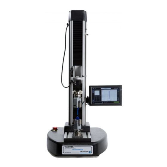
Ametek Chatillon CS1100 User Manual
Force tester
Hide thumbs
1
2
3
4
5
6
Table Of Contents
7
8
9
10
11
12
13
14
15
16
17
18
19
20
21
22
23
24
25
26
27
28
29
30
31
32
33
34
35
36
37
38
39
40
41
42
43
44
45
46
47
48
49
50
51
52
53
54
55
56
57
58
59
60
61
62
63
64
65
66
67
68
69
70
71
72
73
74
75
76
77
78
79
80
81
82
83
84
85
86
87
88
89
90
91
92
93
94
95
96
97
98
99
100
101
102
103
104
105
106
107
108
109
110
111
112
113
114
115
116
117
118
119
120
121
122
123
124
125
126
127
128
129
130
131
132
133
134
135
page
of
135
Go
/
135
Contents
Table of Contents
Bookmarks
Table of Contents
Table of Contents
1 Introduction
Safety
Electrical Safety
Operational Precautions
2 Installation
Unpacking
Setting up Your Force Tester
Voltage Selection and Fuses
Control Console and Load Cell Cables
Mounting the Control Console
Connecting the Control Console Power Cable
Connecting the Control Console Usb Cable
Connecting the Load Cell External Cable
On-Off Switch
Emergency Stop Switch
Load Cells
3 Initial Configuration
General
Initial Log-In
Languages
Date and Time
Screen Saver and Power Options
Usb Printer
Company Logo on Printed Reports
Network Connection
Windows Password
Touch Screen Calibration
Exiting Windows to Start the Dedicated Program
4 Dedicated Program Configuration
Log-In and the Home Screen
User Settings
Setting Default Units
Changing the Safety Settings
Grip Protection
Pinch Load
Slow Jog Speed
Load Cell Calibration Interval
Communications
Overloads
Returning to the Home Screen
Changing Operator
Jog Panel
Turning off the Cs Force Tester
5 Preparing the Force Tester
Fitting a Load Cell
T Slot Table
Lower Anchor Pin
Limit Stops
6 Defining a Test
Notes
7 Single Stage Test Without Saving Data
Basic Settings Screen
Test Limits Screen
Export Settings Screen
Displaying the Test Screen
8 Defining a Compression or Tension Test
Creating a Compression Test File
Creating a Tension Test File
Test File
Basic Settings Screen
Test Limits Screen
Question Screen
Test Results Screen
Archive and Export Settings Screen
Displaying the Test Graph Screen
9 Defining a Multi-Action Test
Creating a Multi-Action Test File
Basic Settings Screen
Select Next Stage Screen
Create a Tension Stage
Create a Cycle Test
Create a Compression Stage
Create a Hold Load Stage
Create a Hold Extension Stage
Create a Zero Stage
Create a User Input Stage
Editing or Deleting a Stage
Adding a Stage
Test Results Screen
Archive and Export Settings Screen
Displaying the Test Graph Screen
10 Using the Force Tester
Performing a Test
Markers and Notes
Printing and Exporting Graph Data
Data Table and Statistics
Printing and Exporting Data Table and Statistics
Test Notes
Loading a Saved Test File
Favorites Feature
Test File Maintenance
Copy a Test
Edit a Test
Delete a Test
Export a Test
Install a Test
11 Distance Compensation
General
Creating a New Distance Compensation
12 Height Mode
Creating a Height Mode Test
Performing a Height Mode Test
13 Load Cells
General Precautions
Additional Load Cells
Load Cell Resolution
14 Installation Notes
Splinter Shield
Securing to the Workbench
15 Error Conditions
16 Cleaning and Maintenance
Cleaning External Finish and Trim
Maintenance
17 Communications
Configuring the Communications
Using the Communications
Ascii Commands
Ascii Commands to Drive the Force Tester
List of All Ascii Commands
18 Technical Specifications
Technical Specification Cs225
Technical Specification Cs1100
19 Overall Dimensions
20 Rohs TABLES
21 Spare Parts Kits
Advertisement
Quick Links
1
Load Cell Calibration Interval
2
Error Conditions
Download this manual
Presented By
Dallas
Ft Worth
Austin
Houston
NicolScales.com
800.225.8181
Contact Us
Nicol Scales & Measurement is an ISO Accredited Calibration
Company that has provided calibration, repair and sales of all types
of weighing and measurement products since 1931.
Table of
Contents
Previous
Page
Next
Page
1
2
3
4
5
Advertisement
Table of Contents
Need help?
Do you have a question about the Chatillon CS1100 and is the answer not in the manual?
Ask a question
Questions and answers
Subscribe to Our Youtube Channel
Related Manuals for Ametek Chatillon CS1100
Test Equipment Ametek JOFRA CSC200 Reference Manual
Compact signal calibrator (21 pages)
Test Equipment Ametek CSC201 User Manual
Compact signal calibrator (26 pages)
Test Equipment Ametek CS2-225 User Manual
Force tester (112 pages)
Test Equipment Ametek CS2-1100 User Manual
Force tester (112 pages)
Test Equipment Ametek Chatillon CS225 User Manual
Force tester (135 pages)
Test Equipment Ametek WT Series Operation Manual
Digital test gauge (19 pages)
Test Equipment Ametek Crystal Pressure Operation Manual
Data entry foot switch (6 pages)
Test Equipment Ametek Teseq CDN 3153-S63 User Manual
Automated 3-ph coupling/decoupling networks (43 pages)
Test Equipment Ametek Jofra CTC-155 A Reference Manual
Compact temperature calibrator (65 pages)
Test Equipment Ametek Jofra CTC-155 B Reference Manual
Compact temperature calibrator (65 pages)
Test Equipment Ametek Jofra CTC-350 B Reference Manual
Compact temperature calibrator (65 pages)
Test Equipment Ametek Jofra CTC-652 B Reference Manual
Compact temperature calibrator (65 pages)
Test Equipment Ametek Jofra CTC-660 B Reference Manual
Compact temperature calibrator (65 pages)
Test Equipment Ametek JofraCloud 3G Gateway Reference Manual
Jofracloud remote calibrator operation for ametek rtc series; ametek ptc series (28 pages)
Test Equipment Ametek LAND R1500T User Manual
Landcal blackbody source (28 pages)
Test Equipment Ametek Crystal pressure XP3i Operation Manual
Digital test gauge (standard and dual-display(dd)) (36 pages)
This manual is also suitable for:
Chatillon cs225
Table of Contents
Print
Rename the bookmark
Delete bookmark?
Delete from my manuals?
Login
Sign In
OR
Sign in with Facebook
Sign in with Google
Upload manual
Upload from disk
Upload from URL


Need help?
Do you have a question about the Chatillon CS1100 and is the answer not in the manual?
Questions and answers