Table of Contents
Advertisement
Quick Links
Advertisement
Table of Contents

Subscribe to Our Youtube Channel
Related Manuals for Ametek Teseq NSG 3150


Summary of Contents for Ametek Teseq NSG 3150
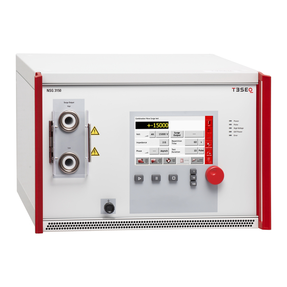
- Page 1 NSG 3150 EMC TEST SYSTEM USER MANUAL 601-340B...
- Page 2 WARNING - Lethal danger from high voltages and the risk of radiating illegal electromagnetic interference. This system must be used only for EMC test purposes as specified in these operating instructions. The NSG 3150 must be installed and used only by authorized and trained EMC specialists.
-
Page 3: Table Of Contents
Content EXPLANATION OF SYMBOLS ..........................5 General description ............................. 5 STANDARDS AND APPLICATIONS........................6 Combination wave ............................6 Pulsed magnetic fields (option) ........................7 SAFETY INSTRUCTIONS ............................ 8 General ................................ 8 Installation ..............................9 Installation of an EUT power switch ......................9 Applicable safety standards ........................ - Page 4 EUT fail input ............................. 42 EUT power off ............................42 High voltage active ............................ 42 TECHNICAL DATA ............................43 COUPLING / DECOUPLING NETWORKS ..................... 44 10.1 CDN 3153-S63 ............................44 VARIOUS NSG 3150 VERSIONS ........................45 11.1 NSG 3060-TS-EXT telecom surge (10 / 700us) extension unit ..............45 MAINTENANCE AND FUNCTION CHECK ....................
-
Page 5: Explanation Of Symbols
EXPLANATION OF SYMBOLS Please take note of the following explanations of the symbols used in order to achieve the optimum benefit from this manual and to ensure safety during operation of the equipment. The following symbol draws your attention to a circumstance where non observation of the warning could lead to inconvenience or impairment in the performance. -
Page 6: Standards And Applications
STANDARDS AND APPLICATIONS The NSG 3150 test system is designed to test lighting, communication and energy distribution equipment, railways and protection systems and relays (e.g. IEC 60255-26). The 15kV surge pulse voltage 1.2/50 µs, 8/20 µs allows manufactures to reach new quality levels, which helps them to outperform competitors. -
Page 7: Pulsed Magnetic Fields (Option)
2.2 Pulsed magnetic fields (option) Tests with pulsed magnetic fields, or PULSEM tests, simulate the type of interference produced by surge pulses as a result of lightning strikes to buildings and other metallic structures such as freestanding masts, ground conductors, grounding networks, etc. as specified in IEC / EN 61000-4-9. -
Page 8: Safety Instructions
SAFETY INSTRUCTIONS The NSG 3150 system and its accessories operate at high voltages. WARNING - Improper or careless operation can be fatal! These operating instructions form an essential part of the equipment and must be available to the operator at all times. The user must obey all safety instructions and warnings. Neither Teseq AG, Reinach, Switzerland, nor any of its subsidiary sales organizations can accept any liability for personal, material or consequential injury, loss or damage that may result from improper use of equipment and accessories. -
Page 9: Installation
3.2 Installation The NSG 3150 test system conforms to protection class 1. Local installation regulations must be respected to ensure the safe flow of leakage currents. WARNING - Operation without a ground connection is forbidden! Operate the equipment only in dry surroundings. Any condensation that occurs must be allowed to evaporate before putting the equipment into operation. -
Page 10: Applicable Safety Standards
3.4 Applicable safety standards The NSG 3150 conforms to the safety requirements and offers all the features necessary for safe and efficient operation. Development and manufacture is in compliance with ISO 9001. The system complies with the safety requirements of IEC / EN 61010-1 (Safety requirements for electrical equipment for measurement, control and laboratory use). -
Page 11: User Warnings Generator
3.6 User Warnings Generator WARNING - Users must be aware of the following dangers that can occur during testing: Local burning, arcing, ignition of explosive gases. EUT supply current surge caused by a flashover or breakdown resulting from the superimposed high voltage. ... -
Page 12: Dangers Concerning The Eut
3.7 Dangers concerning the EUT WARNING - Users must be aware of the following dangers that can occur during testing: EUTs are often functional samples that have not yet been subjected to safety tests. It is therefore possible that the EUT could be damaged by internal overloads or may even start to burn. -
Page 13: First Steps
FIRST STEPS This chapter contains a short checklist with steps that should be taken before the instrument is switched on and put into operation. Check the packaging for signs of damage in transit. Any damage should be reported immediately to the transportation company. Lift the NSG 3150 test system out of its packaging by grasping of the mounted grips. -
Page 14: Installation Of The Nsg 3150 System
4.1 Installation of the NSG 3150 system The mains power voltage indicated on the instrument must correspond with the local supply voltage (mains voltage: 85 to 265 VAC, universal power unit, mains frequency: 50 to 60 Hz). Mains switch, fuse holder and power input To replace a fuse: 1) Disconnect the mains cable 2) Pull the fuse holder out of the connector... -
Page 15: Mainframe Description
MAINFRAME DESCRIPTION The 3150 housing NSG is specially designed for EMC applications and is EMC approved. 5.1 Front panel 5.1.1 Reference ground connector The earth connection between the CDN and the generator is realized via the shield of the HV connectors. -
Page 16: Rear Panel
5.1.4 Touch screen and user interface The color 7” touch screen display controls include a wheel and 3 sensitivity keys used to 1, 10 or 100 steps per wheel click. The Start, Stop, and Pause keys are used to control the procedure. All user interface function menus and sub-menus are described in chapter 7, standard user interface. - Page 17 5.2.2 System interface connector 25 pin D sub Pin # Sync.line Signal Remark Working direction Sync0 Mains synchronization Mains voltage passes through the zero From a coupling network crossing point with rising signal level Sync1 Interlock Puts the NSG 3150 into an idle state. The From each controller...
-
Page 18: The Standard User Interface (Sui)
THE STANDARD USER INTERFACE (SUI) The NSG 3150 Standard User Interface (SUI) consists of – A 7” color touch panel – A wheel for setting parameters – A wheel sensitivity keys labeled 1, 10, and 100 to denote the units –... -
Page 19: Front Panel
6.1 Front panel Main menu NSG 3150 The main menu is displayed following boot-up. The main menu shows the possible pulses or tests which are available (combination wave, surge) in the NSG 3150. Faded generator icons (e.g. Telecom 10 / 700 us pulse and voltage variation) mean, that the generator is configured to generate those pulses but the proper unit is not connected. -
Page 20: System Window
6.2 System window Touch the “System” button to display the “System” window: System window The “System” window displays 4 buttons: GENERAL, EQUIPMENT, COMMUNICATION and MONITORING. In the red bar there are two buttons: FACTORY SETTINGS and EXIT. FACTORY SETTINGS Touch the FACTORY SETTINGS button to reset the properties associated with each of the buttons in the System window to the original factory settings. - Page 21 General settings window when an EUT power switch has been detected. Beeper volume During the surge test there is a beep sound to alert the user. Touch the “Beeper volume” button to switch the sound on and off. Default setting is “On”, for safety purpose. The red vertical bar on the right side of the General settings window displays 4 buttons: “Exit”, “EUT OFF / ON”, “Factory Settings”, and “OK”.
- Page 22 6.2.2 GENERAL settings Equipment window Touch the “Equipment” button to access a list of all internal and external generator modules, including firmware versions, serial numbers, calibration dates and certificate numbers. The red vertical bar on the right of the equipment window displays three buttons: “Exit”, “Up” and “Down”.
- Page 23 6.2.3 COMMUNICATION screen Communication window Touch the “Communication” button to view and enter the network address information required to integrate the NSG 3150 into a local area network or connect it to a PC. By touch the IP address-, SubNet-, Port- or Gateway-field the key board will appear and the new numbers can be added.
- Page 24 Port Network ports can be either physical or virtual connection points. The NSG 3150 has a physical Ethernet port that allows it to be connected to a PC or router. The port address for the NSG 3150 should be set to 1025. Touch the “Port” button to enter the port number.
- Page 25 6.2.4 MONITORING screen Monitoring window Touch the “Monitoring” button to view EUT power input parameters, and to control test activity and EUT power input in the event of EUT failure. EUT Supply Voltage, EUT Supply Frequency In case a CDN 3153-S63 is connected to the NSG 3150, the “EUT Supply Voltage” field displays the actual EUT voltage when the AC EUT input supply is connected and EUT power is switched “On”.
-
Page 26: Updating Sui Software Via The Sc-Card
6.3 Updating SUI software via the SC-card To change the SUI software, first switch off the generator and remove all power cords and cables. Open the top housing cover of the generator as described below. WARNING - Before opening the generator make sure that it is turned OFF and disconnected from all power and signal cables! For complete discharge of the NSG 3150’s internal capacitor we recommend to wait 24 hours, before opening the device. - Page 27 Removing the NSG 3150 side panels and cover The SD-card is placed on the upper right position NSG 3150 SD-card slot Removing the SD-card Windows explorer displaying the SUI program filename (SUI3000AP.EXE) on the SD-card (removable disk (F:) NOTE: Do not change the SUI program filename.
-
Page 28: Parameter Setting Window
PARAMETER SETTING WINDOW The main menu displays a button for every type of test that can be performed by the NSG 3150. Buttons for tests that are not available on the system as configured are greyed out. The user can set parameters for available tests and create new tests in the test parameter window. The next figure shows the test parameter window for burst tests. -
Page 29: The Red Menu Bar
7.1 The red menu bar EXIT Touch the “Exit” button to return to the system window without saving settings. EUT OFF / EUT ON Touch the “EUT Off / EUT On” button to switch EUT power off or on. Note: The EUT power function can work only in combination with an automated accessory, such as a variac, step transformer or automated CDN. - Page 30 SHOW STEPS Touch the “Show Steps” button to view, change the order of, or delete individual test steps. The show step window displays individual test steps in the order that they will be executed. UP / DOWN Use the “UP” and “DOWN” arrows on the right side of the Show Step window to change the test step order.
-
Page 31: The Bottom Bar
7.2 The bottom bar 7.2.1 LOAD USER TEST Touch the “Load User Test” button to display a list of all test files that have been created and saved by the user. Only files for the selected test type are displayed. The Figure below shows the load user test window with several burst tests displayed. - Page 32 7.2.2 LOAD STANDARD TEST The NSG 3150 includes all necessary test libraries corresponding to the latest editions of the IEC basic standards from the IEC / EN 61000-4-x series. They conform to many standard derivate and product standards. Depending on the selected pulse the appropriate IEC standard tests can be selected. Following standard tests are included in the SUI: Combination wave (Surge), IEC 61000-4-5 [1.2/50 μs &...
- Page 33 7.2.3 SAVE TEST The “Save Test” button is used to save the current test to a file for later use. Touch the “Save Test” button. A keyboard is displayed. Touch the individual keys to enter a file name in the black bar above the keyboard. The “Delete”...
- Page 34 7.2.5 SHOW GRAPHICS Touch the “Show Graphics” button to display waveforms, coupling diagrams and other graphical information for the selected test. Touch the “More” button to view additional information. Touch the “Back” button to view previous graphics. Touch the “Exit” button to return to the Test parameters window. Example surge pulse graphs...
-
Page 35: Combination Wave (Surge) Parameter Setting
7.3 Combination wave (Surge) parameter setting The surge test generates high voltage pulses as specified in the international standards EN / IEC 61000-4-5. 7.3.1 Test configuration for power line coupling Test pulses are injected directly into the EUT power supply lines as they pass through the mains CDN 3153-S63. - Page 36 WARNING - Using improper equipment when measuring surge pulses can result in personal injury or equipment damage. NOTE - Teseq recommends using a CIC-Research DP20-20K High voltage differential probe in combination with a Pearson Model 4997 20 kA for surge pulse verification.
- Page 37 7.3.6 Coupling Touch the “coupling mode” button (in the example) to select SURGE OUTPUT, MANUAL CDN or IEC COUPLING. Surge output Select SURGE OUTPUT when a pulse is to be applied directly to the EUT; for example, in component testing of non-powered EUTs. Manual CDN This setting will compensate the loss of an external manual CDN such as the CDN 3083 or CDN 117.
- Page 38 7.3.7 Repetition time Touch the “Repetition time” button (60 in the example) to set the test repetition time. A red frame is displayed around the field. The repetition time may be entered using the wheel or the keypad. Touch the “units” button (s in the example) to set the time unit. Time units are s and min. 7.3.8 Test duration Touch the “Test Duration”...
-
Page 39: Pulsed Magnetic Field Testing (-4-9) Parameter Setting
7.4 Pulsed magnetic field testing (-4-9) parameter setting Tests with pulsed magnetic fields simulate the type of field produced by surge pulses such as those occurring during lightning strokes on buildings and other metallic structures such as free-standing masts, lightning conductors, earth networks, etc. The NSG 3150 in conjunction with the pulse wave shape adaptor and a loop antenna it generates these fields in accordance with the IEC 61000-4-9 standard by inducing a surge current into magnetic field loop. -
Page 40: Description Of The 25 Pin D-Sub Signals
DESCRIPTION OF THE 25 PIN D-SUB SIGNALS Good EMC engineering practices should be applied when connecting signals to this port. As the whole system generates disturbances, in order to avoid auto disturbing, all wires connected to this port should be properly shielded, the shield of the cable not serving as signal return path, the shield to be connected via a large surface to the conductive shell of the Sub-D plug. -
Page 41: Trigger To Scope Output Signal
This connection is an integral part of the interlock safety circuit. If a number of units are incorporated in a system, then these connections can be “daisy-chained” together to form a single safety circuit. If no external interlock circuit is required, then the shorting connection must be made by using the terminator connector supplied. -
Page 42: Eut Fail Input
8.5 EUT fail input Between pin 6 (hi) and pin 2, 8, 15, 20 (low) Input open = inactive; input shorted = active This connection serves as a control input that can be activated externally. The EUT can activate this input if it is capable of reporting a disturbance effect caused during an EMC test. -
Page 43: Technical Data
TECHNICAL DATA Parameter Value Pulse voltage (open circuit): ± 500 V to 15.0 kV (in 1 V steps) Pulse current (short circuit): ± 250 A to 7.5 kA 2 / 12 Ω Impedance: Polarity: Positive / negative / alternate Phase synchronization: Asynchronous, synchronous 0°... -
Page 44: Coupling / Decoupling Networks
10 COUPLING / DECOUPLING NETWORKS These CDN 3153-S63 is fully automatic controlled, featuring plug and play technology - just connect them to the NSG 3150 and they will auto detect and auto configure at system power up, available coupling possibilities will show up in respective test windows. All CDN 3153-S63 feature: ... -
Page 45: Various Nsg 3150 Versions
11 VARIOUS NSG 3150 VERSIONS 11.1 NSG 3060-TS-EXT telecom surge (10 / 700us) extension unit NSG 3060-TS-EXT The NSG 3060-TS-EXT is an extension chassis for the NSG 3040/60 and NSG 3150 series which contains the functionality to generate the so called telecom surge pulse (10 / 700 us). With its pulse voltage up to 7.7 kV it fully complies not only with IEC 61000-4-5 but also with the highest requirements of the ITU-TK series standards. -
Page 46: Maintenance And Function Check
12 MAINTENANCE AND FUNCTION CHECK 12.1 General Inside the test system there are no adjustable elements accessible to the user neither for calibration nor for maintenance purpose. The housing of the test system must not be opened (except for SW update via SD-card). Should any maintenance or adjustment become necessary, the whole test system, together with an order or fault report, should be sent to a Teseq service center. -
Page 47: Warranty
12.5 Warranty Teseq grants a warranty of 2 years on this test system, effective from the date of purchase. During this period, any defective components part will be repaired or replaced free of charge or, if necessary, the test system will be replaced by another of equivalent value. The decision regarding the method of reinstating the functional capability is at the sole discression of Teseq. -
Page 48: Declaration Of Conformity (Ce)
The user himself or herself is ultimately responsible for the correct and controlled operation of the rig. In case of doubt, the tests should be carried out in a Faraday cage. European representative Manufacturer AMETEK CTS Germany GmbH Teseq AG Lünenerstr. 211 Sternenhofstr. 15... -
Page 49: Accessories
14 ACCESSORIES The NSG 3150 is suitable for perform surge impulses up to 15 kV There are many surge applications where the NSG 3150 is suitable with using auxiliary equipment that is rated for lower surge voltages. When using accessories rated for lower surge impulse voltages, the user is responsible not to test with higher voltages than the used equipment is rated. -
Page 50: Magnetic Field Options
14.2 Magnetic field options The NSG 3150 is suitable for perform pulsed magnetic field tests as per IEC 61000-4-9. The user is responsible that the applied surge impulse voltage is in a Range up to 1000 A/m that corresponds to a surge impulse voltage of approx..2300V. - Page 51 INA 702 The INA 702 is a 1 x 1 m loop - 11 turns – coil factor 9.8 - when fitted with the power plug. It enables the generation of field strengths of up to 40 A / m for mains frequency fields 50 or 60 Hz when used with the MFO 6501 or MFO 6502 current sources.
-
Page 52: Pulse Wave Shape Adapter Ina 752
14.3 Pulse wave shape adapter INA 752 The pulse waveshape adapter INA 752 is a standard accessory for the Teseq NSG 3000 series. It provides a convenient means for interconnecting the NSG 3150 surge generator with the loop antennas INA 701 or 702 and insures that the generated pulsed magnetic field has the waveshape as specified in the application standard. -
Page 53: Coupling Decoupling Networks For Data Lines
14.4 Coupling decoupling networks for data lines 14.4.1 Surge CDN for unsymmetrical data lines CDN 117 Teseq’s CDN 117 coupling-decoupling network enables convenient testing with surge pulses of 1.2 / 50 μs on data, signal or peripheral lines, as specified in many product standards. The test method, severity levels, permissible reaction of the EUT and specification of the coupling networks are included in IEC / EN 61000-4-5. - Page 54 14.4.2 Surge pulse CDN for symmetric datalines CDN 118 Teseq’s CDN 118 coupling-decoupling network is designed for convenient surge testing of telecommunications equipment to IEC / EN 61000-4-5, which specifies a 1.2 / 50 or a 10 / 700 μs pulse.
-
Page 55: Measuring Accessories
14.5 Measuring accessories 14.5.1 CIC-Research DP20-20K differential high voltage probes The CIC-Research DP20-20K high voltage differential probes are ideally suited to allow EMC engineers to verify their conducted EMC test generators periodically. Their performance permits to be used for many other purposes where higher voltages have to be measured in a potential free manner. Annual calibration and periodic verification The annual calibration of test equipment recommended by most of the quality systems (ISO 9000, ISO 17025, etc.) has to be considered as a validation of all measurements done since the last... - Page 56 14.5.2 Pearson Model 4997 surge pulse current probe for 20 kA The Model 4997 probe has been specially designed to verify surge current pulses as specified in IEC / EN 61000-4-5. The main advantage of the Model 4997 current probe is, that the measuring system is physically isolated from the circuit under test.
- Page 57 14.5.3 Calibration adapters (Accessories) INA 3154 15 kV pulse verification box 18 µF capacitor for NSG 3150 Dimension: 250mm x 160 mm x 155 mm Connection cable to generator: 0.5 m Weight: 3.9 kg INA 3155 Pulse verification voltage probe adapter Surge calibration adapter set of 2 pieces to connect CDN 3153-S63 to the HV...
-
Page 58: System Description
15 SYSTEM DESCRIPTION Parameter Value Dimensions NSG 3150: (17.7”) 449 mm (12.9”; 7 HU) 310 mm (22.2”) 565 mm Weight NSG 3150: 41.2 kg (90.8 lb) approx. Dimensions CDN 3153-S63: (21.8”) 554 mm (43.5”; X HU) 1105 mm (23.6”) 600 mm Weight CDN 3153-S63: 234 kg (516 lb) approx. - Page 59 Teseq Ltd. T +49 2307 26070-0 T +44 845 074 0660 info.cts@ametek.de uksales@teseq.com Japan AMETEK Co., Ltd. Nagoya Office Teseq Inc. / AMETEK CTS T +81 52 709 5501 T +1 732 417 0501 cts-japan.sales@ametek.co.jp Toll-free +1 888 417 0501 usasales.cts@ametek.com...
Need help?
Do you have a question about the Teseq NSG 3150 and is the answer not in the manual?
Questions and answers