Table of Contents
Advertisement
the benchmark for emc
M a n u a l
F o r
O p e r a t i o n
AutoWave
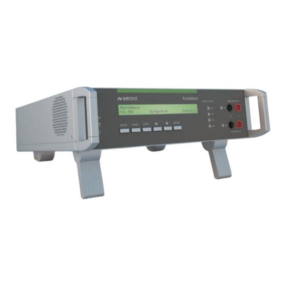
Portable solution to simulate and
measure Battery Supply Voltage
Variation
FM Version ≥ 8.03.04
The Automotive industry is facing the necessity to investigate
the behavior of the battery voltage variations and their effects to
electronic components connected to the supply network of the
cars, testing emission and immunity.
The
two
major
international
procedures to simulate different phenomena's related to the
battery supply lines are ISO 16750-2 for 12V and 24V supply
voltages and ISO 21780 for 48V supply voltage.
Version: 5.11.0/ 18.05.2022
Replaces: 5.10.2/ 10.07.2018
Filename:
UserManual-AutoWave-E-V5.10.2.doc
Printdate: 24.05.22
standards
describing
• ISO 7637-2
• ISO 16750-2
• ISO 21780
• SAE J1113
• Manufacturer spec as
test
per GM, Ford, Chrysler,
Mercedes, BMW, VW,
PSA, Fiat ......
Advertisement
Table of Contents

Related Manuals for Ametek AutoWave


Summary of Contents for Ametek AutoWave
- Page 1 M a n u a l F o r O p e r a t i o n AutoWave Portable solution to simulate and measure Battery Supply Voltage Variation FM Version ≥ 8.03.04 • ISO 7637-2 The Automotive industry is facing the necessity to investigate •...
- Page 2 Sternenhofstrasse 15 4153 Reinach BL1 Switzerland Phone: +41 61 717 91 91 Fax: +41 61 717 91 99 URL: http://www.ametek-cts.com Copyright © 2022 Ametek CTS GmbH All right reserved. Specifications subject to change Manual for Operation V 5.11.0 2 / 47...
- Page 3 AMETEK CTS AutoWave Foreword Thank you for purchasing the AutoWave generator. This user’s manual lists precautions that must be taken during use, and contains useful information about the functions and operating procedure of the device. To ensure correct use, please read this manual thoroughly before beginning operation. After reading the manual, keep it in a convenient location for quick reference whenever a question arises during operation.
-
Page 4: Table Of Contents
Calibration and Verification ....................... 39 6.2.1. Factory calibration ..........................39 6.2.2. Guideline to determine the calibration period of AMETEK CTS instrumentation ......39 6.2.3. Calibration of Accessories made by passive components only: ............39 6.2.4. Periodically In-house verification ...................... 39 6.3. -
Page 5: Model Overview
Only compliant with the standard when using a VDS 200Qx.2 generator * Depending on the production date, some AutoWave and AutoWave-WR models have this feature firmly built in. For identification see page 13. ** Availabilty depends on age of the AutoWave unit. -
Page 6: Put In Service Functions
AMETEK CTS AutoWave Put in service Functions 2.1. Front view LED Power Cursor "" "→" LED Running Setup LED Trigger LED display output channels 1...4 Mode 10 LED display input channels 1...2 Start 11 Input channel 1 & 2 (option) - Page 7 AMETEK CTS AutoWave 6. Stop Stop button for measurement and running arbitrary waves. STOP: Stops a measurement or a running Arbwave STOP: Exit the record or play function 7. Cursor key "" "→" Cursor Key with the following functions - Scrolling in the menus - Setting the values up / down 8.
-
Page 8: Rear View
AMETEK CTS AutoWave 2.2. Rear view Fuse F2 AC 1A 1 Output channel 1...4 Mains 90V – 250V 2 Framebus IN / OUT 10 Trigger IN1 / IN2 3 CAN port 11 Trigger OUT1 / OUT2 4 Ethernet port 12 DUT monitor 5 USB port 13 DC supply 12 –... - Page 9 AMETEK CTS AutoWave 3. CAN port CAN port 9 pole Sub D female connector Pin assignment 1: nc 2: CAN_L The Philips PCA82C251 CAN transceiver for 24V 3: CAN GND system serves as the interface between the CAN 4: nc protocol controller and the physical bus.
- Page 10 AMETEK CTS AutoWave 9. Mains input The plug is part of the mains filter. (90 - 250V / 1A) 10. Trigger IN Trigger input for event triggering. This trigger inputs are connected directly to the DSP signal processor. Input Signal: Negative slope...
- Page 11 AMETEK CTS AutoWave 11. Trigger OUT Trigger outputs for event triggering. This trigger outputs are generated from the DSP signal processor. Max. voltage: 24V (pull up) Current: 100mA : For use the trigger out the user has to connect an external DC source...
- Page 12 The segments can be individually selected in autowave.control software. 1)Trigger selection 2)Trigger spot in graphic The Autowave can be prepared from the factory with a built-in pullup circuit with option OPT AW-TRIG PU. 12. DUT monitor DUT monitor for any fail detection.
- Page 13 DC input voltage range: 12V – 32V dc Not available on all models. Only AutoWave until June 2021 and AutoWave-WR. 14. Power on switch Power ON switch for AutoWave. The system needs approx. 35 seconds for booting. 15. OPT AW1-FAST The label “OPT AW1-FAST indicates, the AutoWave includes a modification, to meet faster rise and fall time requirements of <3us at the VDS 200Qx.2...
-
Page 14: Put In Service
2.3.2. Installation in a System The AutoWave is used to control one or more DC sources and / or for measuring and recording of the transient behavior of a voltage during a sequence. 2.3.2.1. Installation or mount in a 19” Rack 1. -
Page 15: Hardware Wiring
AMETEK CTS AutoWave 2.3.3. Hardware wiring There are two solutions to connect the computer to the AutoWave. - IEEE connection - Ethernet connection Both interface connections are applicable. Depends of the implementation AMETEK CTS propose the IEEE or Ethernet interface. - Page 16 AMETEK CTS AutoWave 2.3.3.1. Wiring Devices Wiring Setup example with: AutoWave UCS 200 VDS 200N LD200 Manual for Operation V 5.11.0 16 / 47...
- Page 17 Supply connections from VDS200 to UCS200 and PFS200 can be wired inside the rack. Note: Do never connect The PFS200 output 0-10V in parallel with any AutoWave output. In this case the controlled DC source will deliver a wrong output signal. It is not allowed to connect two output sources in parallel.
- Page 18 AMETEK CTS AutoWave Setup 3: example with: This configuration is suitable for testing Ford AC CI-230 tests with four waves at the Rack 1 same time. The figure shows the output for: RDS 200 RDS 200 - General tests at UCS output...
- Page 19 AMETEK CTS AutoWave Setup 4: example with: Rack MPG 200 LD 200 PFS200 VDS 200N EFT 200 CNA 200 AutoWave for replace ARB 2714 Manual for Operation V 5.11.0 19 / 47...
- Page 20 AMETEK CTS AutoWave 2.3.3.2. Wiring examples with AMP 200 Setup 5: example with: Rack LD 200N AMP 200N AutoWave UCS 200N VDS 200N Manual for Operation V 5.11.0 20 / 47...
- Page 21 AMETEK CTS AutoWave Setup 7: example with: Rack 1 RDS 200 RDS 200 RDS 200 AMP 200N AutoWave PFS 200N VDS 200N Rack 2 LD 200N UCS 200N Setup 8: example with: Rack 1 RDS 200 RDS 200 AMP 200N...
- Page 22 AMETEK CTS AutoWave 2.3.3.3. Setup with PFM 200N100 Setup 11: example with: Rack AutoWave PFM 200N100 VDS 200N Manual for Operation V 5.11.0 22 / 47...
- Page 23 AMETEK CTS AutoWave 2.3.3.4. Setup with AutoWave and VDS 200Q and PFM 200N100 Setup 12: example with: Rack AutoWave PFM 200N100 VDS 200Q 25, Q 50 External: AMP 200 Manual for Operation V 5.11.0 23 / 47...
- Page 24 AMETEK CTS AutoWave 2.3.3.5. Setup with AutoWave and VDS 200Q and PFM 200N100 Setup 13: example with: Rack AutoWave VDS 200Q100 External: PFM 200N100 Manual for Operation V 5.11.0 24 / 47...
-
Page 25: Hardware Wiring Autowave To Sng 200P
AMETEK CTS AutoWave 2.3.4. Hardware wiring AutoWave to SNG 200P The setup below is for programming the SNG 200P via the Autowave Manual for Operation V 5.11.0 25 / 47... -
Page 26: Operation
Power on After switching on, AutoWave needs approx. 35s for booting. During this time the display is blank. AutoWave is ready when the display shows AutoWave and the current version. The AutoWave is operated by an easy menu control system. Five function keys are available to select parameters and functions. - Page 27 - Play files The output active LED indicates the output channel(s) of the selected file. Note: Files with multiple waves indicates all used output channels. The software AutoWave delivers the detailed information about the wave on each channel. status blinking:...
- Page 28 AMETEK CTS AutoWave Start, Break and Restart same file Start, Stop and return to WaveGenerator menu Manual for Operation V 5.11.0 28 / 47...
- Page 29 AMETEK CTS AutoWave 3.2.1.2. Menu Wave Recorder Functions Recording the voltage variation in the lab setup. Replay of the measured data via an adequate dc source or amplifier. Check of the DUT under real world conditions. Channel selection Recording Manual for Operation V 5.11.0...
- Page 30 AMETEK CTS AutoWave 3.2.1.3. Menu Wave Manager Functions - Copy file to USB Memory stick - Load file from USB Memory stick - Delete file Function selection Select a file and - Delete - Copy - Load Manual for Operation V 5.11.0...
-
Page 31: Setup Menu
AutoWave 3.2.2. Setup Menu In the setup menu all settings of the AutoWave can be done manually. The following figures show the configuration of the different parameters. How to navigate in the Setup menu Figure 4.2 shows the handling of the Setup menu. The small buttons inside the circle shows how to step through the menu or parameter list. -
Page 32: Dc Source
3.2.3. DC Source Parameter to control the connected voltage source. This setting must be done for each channel CH1...CH4 with a connected voltage source. AutoWave calculates automatically the correct output signal for controlling the source. Channel Selected output channel for setting the parameters... -
Page 33: Sample Frequency (Only With The Option Record)
AMETEK CTS AutoWave 3.2.4. Sample frequency (only with the option record) Sample frequency for data recording. The max. sampling frequency is limited by the number of used measuring channels. Sampling frequency Default 5kS/s Sampling Frequency [kHz] depends on the number of channels... -
Page 34: Dut Monitor
- Notify: Message will be written on a file - Stop: Wave stops and continue according the user decision 3.2.8. GPIB Address GPIB Address for using the AutoWave with the software iso.control Standard: IEEE 488 Address: 1...30 Default: Default address for iso.control software 3.2.9. -
Page 35: Date
AMETEK CTS AutoWave 3.2.12. Date Day: 1...31 Month: 1...12 Year: 2000...2200 Note: When pressing Setup to exit the Date setup, the display returns after few seconds delay to the Configuration display 3.2.13. Time The time is used for mark the stored files. -
Page 36: Test Equipment
AC input The AC mains power input is a wide range AC input that allows to operate the AutoWave in every country of the world. With the voltage input range from 90V ... 250V and 47Hz ... 63Hz it is not necessary to use an adapter transformer. -
Page 37: Technical Data
Segment duration Unlimited Segments per wave form 20-30 depends on the complexity of the segment WaveRecorder Number of input channels 2 channels (only AutoWave-WR) Input voltage ranges 5V, 10V, 20V, 50V and 100V; unipolar or bipolar Resolution 16 Bit Accuracy better than 0.2%... - Page 38 Safety design per IEC 1010, EN 61010 Power supply AC: 90V ... 250V , 47Hz...63Hz DC: 12V ... 32V, filtered and buffered (only AutoWave-WR model) Fuses F1: 3.15 A slow blow (DC) F2: 1.00 A slow blow (AC) Power requirement 40W max.
-
Page 39: Maintenance
In reply to all these questions we like to approach this issue as follows: AMETEK CTS make use of a solid state semiconductor switch technique to generate high voltage transients. A precious advantage of this technique is the absolute lack of periodical maintenance effort. In consequence thereof a useful calibration period has to be defined based on two criteria: The first one is the customer’s Quality Assurance Policy. -
Page 40: Calibration
AMETEK CTS AutoWave 6.3. Calibration For periodical calibration the AutoWave has to return back to the manufacturer 6.4. Verification A verification can be done with the following procedure: Output channel Setting a defined voltage to the output channel and verification with a DMM (5½ digit) Measuring: 0.00V... -
Page 41: Useful Accessories
D-Link : DUB-E100 For communication with the AutoWave via Ethernet a Hi-Speed USB 2.0 Fast Ethernet Adapter type DUB-E100 is available. This connection is used if the AutoWave is not installed in a rack with other AMETEK CTS equipment. Product Features: •... -
Page 42: Annex
1. Press the OK button to enter the Device update window. B: When the user has different firmware versions to operate with the AutoWave. 1. Press the Update button in the device setup for enter the Device update window. Actual Firmware Version field: Firmware version being installed in the AutoWave. - Page 43 A bar graph shows the booting progress. After a successful update the actual firmware of the AutoWave is displayed in the field “Actual Firmware Version”. 4. Press the OK button to return to the Device Setup Window.
-
Page 44: Basic Waves
8.2. Basic Waves The AutoWave generates the waves like an arbitrary generator as PointWaves, where all samples are stored in a file. As an advantage the AutoWave firmware generates the waves as segmented waves from a parameter list. This has the advantage to save a lot of memory and to create waves who can not be realized by PointWaves. - Page 45 AMETEK CTS AutoWave Profile Square Ramp Manual for Operation V 5.11.0 45 / 47...
-
Page 46: Declaration Of Ce-Conformity
AMETEK CTS AutoWave 8.3. Declaration of CE-Conformity Manufacturer: AMETEK CTS GmbH Address: Sternenhofstr. 15 CH 4153 Reinach Switzerland declares, that under is sole responsibility, the product’s listed below, including all their options, are conformity with the applicable CE directives listed below using the relevant section of the following EC standards and other normative documents. -
Page 47: Autowave - General Diagram
AMETEK CTS AutoWave 8.4. AutoWave - General Diagram Manual for Operation V 5.11.0 47 / 47...
Need help?
Do you have a question about the AutoWave and is the answer not in the manual?
Questions and answers