Table of Contents
Advertisement
Quick Links
Advertisement
Table of Contents

Related Manuals for Ametek Teseq NSG 3060


Summary of Contents for Ametek Teseq NSG 3060
- Page 1 NSG 3060 EMC TEST SYSTEM USER MANUAL 601-273F...
- Page 2 NSG 3060 EMC TEST SYSTEM USER MANUAL 601-273F NSG 3060 EMC test system...
-
Page 3: Table Of Contents
CONTENTS Explanation of symbols Introduction General description Standards and applications Burst test Combination wave and ring wave test Telecommunication wave test Mains quality test Magnetic fields with mains frequency (option) Pulsed magnetic fields (option) Safety instructions General Installation Installation of an EUT power switch Applicable safety standards Test execution User warnings - Generator... - Page 4 6.1.5 Indicator LEDs 6.1.6 Touch screen and user interface Rear panel 6.2.1 Instruments mains input 6.2.2 AC EUT mains input 6.2.3 DC EUT input 6.2.4 Ground connection point 6.2.5 System interface connector 25 pin D sub 6.2.6 Synchro-Bus system The standard user interface (SUI) Main menu System window 7.2.1...
- Page 5 8.3.12 Derating Combination wave (Surge) parameter setting 8.4.1 Test configuration for power line coupling 8.4.2 Test configuration for external coupling 8.4.3 Voltage 8.4.4 Impedance 8.4.5 Phase 8.4.6 Coupling 8.4.7 Repetition time 8.4.8 Test duration 8.4.9 Surge generator technical data Ring wave (RW) 8.5.1 Test configuration for power line coupling 8.5.2...
- Page 6 8.7.8 Dips and interrupts technical data 8.7.9 Variation test technical data Power frequency magnetic field testing (-4-8) parameter setting Pulsed magnetic field testing (-4-9) parameter setting Description of the 25 pin D-Sub signals Interlock Trigger to scope output signal Synchronization (Sync) signal: Output signal Pulse enable / next step input EUT fail input EUT power off...
- Page 7 14.2 Variable voltage sources 14.2.1 Automatic Variacs 14.2.2 Manual step transformer: INA 6501 14.2.3 Manual step transformer: INA 6502 14.3 Magnetic field options 14.3.1 Manual solution: MFO 6501 14.3.2 Automatic solution: MFO 6502 14.4 Pulse wave shape adapter INA 752 14.5 Coupling decoupling networks for data lines 14.5.1 Burst EFT coupling clamp NSG 3425 - and safety cover INA 3825...
- Page 8 WARNING - Lethal danger from high voltages and the risk of radiating illegal electromagnetic interference. This system must be used only for EMC test purposes as specified in these operating instructions. The NSG 3060 must be installed and used only by autho- rized and trained EMC specialists.
-
Page 9: Explanation Of Symbols
1 EXPLANATION OF SYMBOLS Please take note of the following explanations of the symbols used in order to achieve the optimum benefi t from this manual and to ensure safety during operation of the equipment. The following symbol draws your attention to a circumstance where non- observation of the warning could lead to inconvenience or impairment in the performance. -
Page 10: Introduction
2 INTRODUCTION 2.1 General description The NSG 3060 test system enables cable-borne EMC (electromagnetic com- patibility) immunity tests to be carried out on electrical equipment intended for household, offi ce, light industrial or commercial use. The test system is a concept from Teseq AG for electromagnetic immunity testing purposes and fulfi lls the requirements to accomplish CE marking. - Page 11 This modularity enables the function units to be re-combined in ever newer instruments and subsystems. The function units can be readily expanded to cope with new standards and new function units for new parameters can be incorporated in existing systems. To ensure optimal user and equipment safety, only industry-standard and cor- rectly specified plugs and sockets are used throughout.
-
Page 12: Standards And Applications
3 STANDARDS AND APPLICATIONS The NSG 3060 test system is designed primarily for cable-borne transient inter- ference tests as specifi ed in the European generic standards IEC / EN 61000-6-1 covering equipment for household, offi ce and light industrial use, and IEC / EN 61000-6-2 for applications in industrial environments. -
Page 13: Combination Wave And Ring Wave Test
methods. The EUT is connected to the mains power socket on the front panel of the test system for the direct mains injection test. Capacitively coupled tests require the interference to be superimposed onto the signal or data line cables via an external coupling clamp that is connected to the burst output on the front panel of the system. -
Page 14: Mains Quality Test
and several EN standards and the safety standard of UL 1950. Since tolerance can be taken into account, it will cover the 9 / 720 µs pulse given in ANSI-TIA- 968_B. Therefore the pulse will fulfil the new IEC recommendation of open circuit voltage of 10 / 700 µs and the short circuit current pulse measuring of 5 / 320 µs. - Page 15 such fields. The NSG 3060 performs this test by causing a heavy current to flow in a magnetic field coil such that the amplitude of the pulse current produces a proportional field within the coil parameters. The magnetic field coils, available as accessories, are connected to the surge pulse output socket via an INA 753 pulse shaping network.
-
Page 16: Safety Instructions
4 SAFETY INSTRUCTIONS The NSG 3060 system and its accessories operate at high voltages. WARNING - Improper or careless operation can be fatal! These operating instructions form an essential part of the equipment and must be available to the operator at all times. The user must obey all safety instruc- tions and warnings. -
Page 17: Installation
WARNING - Because of its construction, the NSG 3060 is not suitable for use in an explosive atmosphere. WARNING - Personnel fitted with a heart pacemaker must neither operate the instrument nor approach the test setup while a test is being executed. Only approved accessories, connectors, adapters, etc. -
Page 18: Installation Of An Eut Power Switch
The test system may only be opened by a qualified specialist upon specific instruction given by the manufacturer. Since the instrument works, on prin- ciple, with two independent power supplies (one for the generator and one for the EUT), the NSG 3060 must be disconnected from both sources before any modifications to the test setup are undertaken. -
Page 19: Test Execution
system itself does not produce any excessive radiation; however, the injection of interference pulses into the EUT can result in the device and / or its associated cables radiating EMI. To avoid radiating unwanted interference the standards organzations recommend that the test setup be located in a Faraday cage. Since the purpose of the test system is to produce interference signals for interference immunity testing, the requirements in the IEC / EN 61000 series concerning limiting the radiated EMI can only be complied with by operating... -
Page 20: User Warnings - Generator
4.6 User warnings - Generator WARNING - Users must be aware of the following dangers that can occur during testing: Local burning, arcing, ignition of explosive gases. EUT supply current surge caused by a flashover or breakdown resulting from the superimposed high voltage. -
Page 21: Dangers Concerning The Eut
4.7 Dangers concerning the EUT WARNING - Users must be aware of the following dangers that can occur during testing: EUTs are often functional samples that have not yet been subjected to safety tests. It is therefore possible that the EUT could be damaged by internal overloads or may even start to burn. -
Page 22: First Steps
5 FIRST STEPS This chapter contains a short checklist with steps that should be taken before the instrument is switched on and put into operation. Check the packaging for signs of damage in transit. Any damage should be reported immediately to the transportation company. Lift the NSG 3060 test system out of its packaging by grasping of the mounted grips. -
Page 23: Installation Of The Nsg 3060 System
5.1 Installation of the NSG 3060 system The mains power voltage indicated on the instrument must correnspond with the local supply voltage (mains voltage: 85 to 265 VAC, universal power unit, mains frequency: 50 to 60 Hz). Mains switch Fuse-holder with fuses 2 x 3.15 AT Mains power input Mains switch, fuse holder and power input To replace a fuse:... -
Page 24: Connecting The Test System To The Ground Reference Plane
NOTE: Your NSG 3040 generator has been delivered with a correctly rated power supply cable. If the cable needs to be replaced, the user needs to make sure the new cable is suited for the rated supply voltage and current. 5.2 Connecting the system to the ground reference plane As mentioned in the standard, the generator must be placed on a ground ref- erence plane which is connected to ground. -
Page 25: Mainframe Description
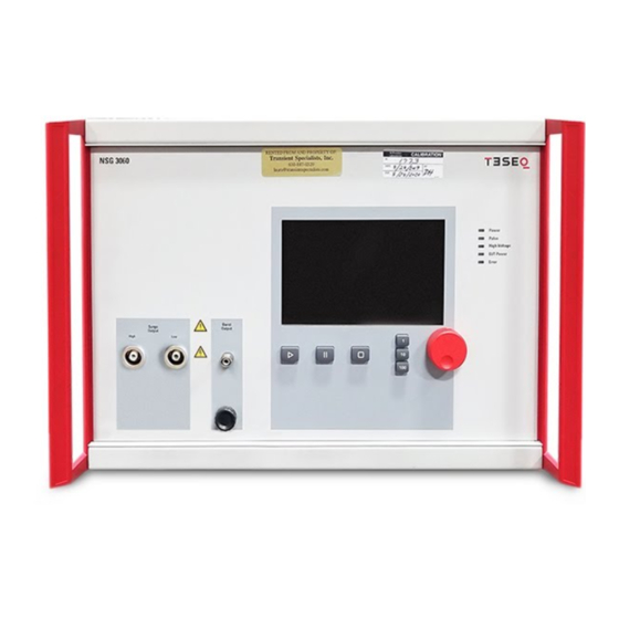
6 MAINFRAME DESCRIPTION The 3060 housing NSG is specially designed for EMC applications and is EMC approved. Burst output 6.1 Front panel Start / Stop / Pause button Surge low output Color touch screen Surge high output LEDs Reference ground connector ground point Wheel Surge low input... -
Page 26: Reference Ground Connector
EUT output connection Note: For DC power supply L = positive (+), N = negative (-). The pins in the connector are designed for a maximum current of 16 A. WARNING - Never attempt to connect or disconnect an EUT while a test is being performed. 6.1.2 Reference ground connector This terminal provides a solid reference ground connection point to the test system. -
Page 27: Surge Output Sockets
6.1.3 Surge output sockets These sockets (high, low) connects the surge output signal to a 1-phase or 3-phase coupling unit or to another external coupling unit. These coaxial sockets are also used to connect the generator to the optional magnetic field coil for tests with pulsed magnetic fields. The surge output is potential free (floating). -
Page 28: Rear Panel
6.2 Rear panel System configured with NSG 3060 (top) with CDN 3061 (bottom). Mains power on / off switch and fuse holder Mains power connection Spare interface slot Master controller, with Ethernet connector System interface connector Ground connection point System interface input System interface output Mains power connection, on / off switch and fuse holder... -
Page 29: Ac Eut Mains Input
6.2.2 AC EUT mains input The EUT mains input is the connection point for the power source which sup- plies power to the EUT. The 4-pin connector is a special 16 A type. A mating plug with 2 m of cable for supplying the EUT from a normal mains outlet is included with the system. - Page 30 Wire 2.5 mm2 Wire 1.5 mm2 Wire 1.0 mm2 °C Ambient temperature The additional variable voltage pole contact (Lb, No.3) enables a variac or alter- native AC source, or a DC source to be connected for PQT tests. In this way the voltage at the phase (L) line at the EUT output connector can be varied in relation with the voltage at this contact.
-
Page 31: Dc Eut Input
6.2.3 DC EUT input For DC voltages: La = positive (+), N = negative (-) In DC applications, the positive and negative lines are to be connected to La and N respectively. The polarity at this EUT power input connector must be the same as at the EUT output connector. -
Page 32: Synchro-Bus System
Pin # Sync.line Signal Remark Working direction Sync5 EUT power OFF Connecting this PIN to From external device GND24S will force the EUT to the slave and power to OFF. master controllers Note: First EUT power needs to be switched ON via the instrument front panel or WIN 3000 Software, This allows dual... - Page 33 The interfaces for the interbus, interlock and synchro-bus are bundled together in a sub-miniature D-connector. These three interfaces are looped through from one instrument to another. NOTE - Good EMC engineering practices should be applied when connecting signals to this port. As the whole system generates disturbances, in order to avoid auto disturbing, all wires connected to this port should be properly shielded, the shield of the cable should not...
-
Page 34: The Standard User Interface (Sui)
7 THE STANDARD USER INTERFACE (SUI) The NSG 3060 Standard User Interface (SUI) consists of – A 7” color touch panel – A wheel for setting parameters – A wheel sensitivity keys labeled 1, 10, and 100 to denote the units –... -
Page 35: Main Menu
SUI boot-up screen 7.1 Main menu Main menu NSG 3060 The main menu is displayed following boot-up. The main menu shows the pos- sible pulses or tests which are available to the user, depending on the NSG 3060’s configuration. Faded generator icons (e.g. Telecom 10 / 700 us pulse and voltage variation) mean, that the generator is configured to generate those pulses but the proper unit is not connected. -
Page 36: System Window
7.2 System window Touch the “System” button to display the “System” window: System window The “System” window displays 4 buttons: GENERAL, EQUIPMENT, COMMU- NICATION and MONITORING. In the red bar there are two buttons: FACTORY SETTINGS and EXIT. FACTORY SETTINGS Touch the FACTORY SETTINGS button to reset the properties associated with each of the buttons in the System window to the original factory settings. - Page 37 General settings window when an EUT power switch has been detected. General settings window when automated variac is connected. Beeper volume During the surge test there is a beep sound to alert the user. Touch the “Beeper volume” button to switch the sound on and off. Default setting is “On”, for safety purpose.
- Page 38 Expert mode Change the “Expert mode” status to “Active” to change parameters during a running test. When the button is set to “Off” parameters can be changed only when the NSG 3060 is in Stop mode. Expert mode is only available for burst pulses (EFT).
-
Page 39: Equipment Screen
7.2.2 EQUIPMENT screen Equipment window Touch the “Equipment” button to access a list of all internal and external genera- tor modules, including firmware versions, serial numbers, calibration dates and certificate numbers. The red vertical bar on the right of the equipment window displays three buttons: “Exit”, “Up”... -
Page 40: Communication Screen
7.2.3 COMMUNICATION screen Communication window Touch the “Communication” button to view and enter the network address information required to integrate the NSG 3060 into a local area network or connect it to a PC. By touch the IP address-, SubNet-, Port- or Gateway-field the key board will appear and the new numbers can be added. - Page 41 A subnet mask defines the boundaries of an IP subnet and hides the network address portion of an IP address. For example, if a network has a base IP address of 192.168.0.0 and has a subnet mask of 255.255.255.0, then any data going to an IP address outside of 192.168.0.X will be sent to that network’s gateway.
-
Page 42: Monitoring Screen
7.2.4 MONITORING screen Monitoring window Touch the “Monitoring” button to view EUT power input parameters, and to control test activity and EUT power input in the event of EUT failure. EUT Supply Voltage, EUT Supply Frequency In case a CDN 304x series, CDN 306x series or an INA 650x is connected to the NSG 3060, the “EUT Supply Voltage”... -
Page 43: Updating Sui Software Via The Sd-Card
on the front panel. When the button is set to “CONT.”, the test will continue even if the EUT fail. EUT Power Supply at EUT Fail Input Touch the “EUT Power Supply at EUT Fail Input” button (not shown on example) to specify the action taken if an “EUT fail signal”... - Page 44 To open the NSG 3060, the user must first remove the sides panels. Each side panel has 4 snap fixtures which will separate when outward pressure is applied. 1. Pull outward on the indentation in the front of the side panel. A blunt tool which will not scratch the paint on the panel may be used.
- Page 45 Removing the NSG 3060 side panels and cover The SD-card is placed on the upper right position. NSG 3060 SD-card slot...
- Page 46 Removing the SD-card Windows explorer displaying the SUI program filename (SUI3000AP.EXE) on the SD-card (removable disk (F:) NOTE: Do not change the SUI program filename. NSG 3060 EMC test system...
-
Page 47: Setting Test Parameters
8 PARAMETER SETTING WINDOW The main menu displays a button for every type of test that can be performed by the NSG 3060. Buttons for tests that are not available on the system as confi gured are greyed out. The user can set parameters for available tests and create new tests in the test parameter window. - Page 48 EUT OFF / EUT ON Touch the “EUT Off / EUT On” button to switch EUT power off or on. Note: The EUT power function can work only in combination with an automated accessory, such as a variac, step transformer or automated CDN. RAMP VALUE The “Ramp value”...
- Page 49 Step delay Touch the “Step delay” button (“1” in the example). A red frame is displayed around the field. Enter the Step Delay value using either the wheel or the keypad. Touch the “Unit” button (“s” in the example) to set the step delay unit.
- Page 50 ADD STEP Multi-step tests can be programmed manually in the test parameters window using the “Add Step” button. Touch the “Add Step” button create a new step with the values currently dis- played in the Test parameters window. The user can program a maximum of 10 test steps.
- Page 51 “Expert Mode” in Burst / EFT Mode For safety reasons the Expert Mode activation needs to be confirmed again when using Burst Mode in the Burst Parameters Screen. Following parameters can be controlled using “Expert Mode”: Volt (please note, the voltage change is only possible if the polarity is set to Negative or Positive) Frequency Phase...
-
Page 52: The Bottom Bar
8.2 The bottom bar 8.2.1 LOAD USER TEST Touch the “Load User Test” button to display a list of all test files that have been created and saved by the user. Only files for the selected test type are displayed. The Figure below shows the load user test window with several burst tests displayed. -
Page 53: Load Standard Test
8.2.2 LOAD STANDARD TEST The NSG 3060 includes all necessary test libraries corresponding to the latest editions of the IEC basic standards from the IEC / EN 61000-4-x series. They conform to many standard derivates and product standards. Additionally some corresponding ANSI / IEEE standards as well as a selection of generic and product standards are available. - Page 54 Ring wave, IEC 61000-4-12 1-Ph Power Lines L-N, major feeder line, 12 Ω, level 1 up to level 4 1-Ph Power Lines L-PE, major feeder line, 12 Ω, level 1 up to level 4 1-Ph Power Lines N-PE, major feeder line, 12 Ω, level 1 up to level 4 1-Ph Power Lines L-N, outlet line, 30 Ω, level 1 up to level 4 1-Ph Power Lines L-PE, outlets line, 30 Ω, level 1 up to level 4 1-Ph Power Lines N-PE, outlets line, 30 Ω, level 1 up to level 4...
- Page 55 Telecom pulse, IEC 61000-4-5 Symmetrical operated all lines to PE, level 1 up to level 4 Shielded I/O communication lines, level 1 up to level 4 Power magnetic field, IEC 61000-4-8 50 HZ CF 9.8, level 1 up to level 4 60 HZ CF 9.8, level 1 up to level 4 Pulsed magnetic field, IEC 61000-4-9 CF 0.98, level 3 up to level 5...
-
Page 56: Save Test
8.2.3 SAVE TEST The “Save Test” button is used to save the current test to a file for later use. Touch the “Save Test” button. A keyboard is displayed. Touch the individual keys to enter a file name in the black bar above the keyboard. The “Delete”... -
Page 57: Show Graphic
8.2.5 SHOW GRAPHICS Touch the “Show Graphics” button to display waveforms, coupling diagrams and other graphical information for the selected test. Touch the “More” button to view additional information. Touch the “Back” button to view previous graphics. Touch the “Exit” button to return to the Test parameters window. Example burst pulse graphs 8.3 Burst parameter setting The generation of high voltage bursts and high frequency pulses is part of... -
Page 58: Test Configuration With Power Line Coupling
8.3.1 Test configuration with power line coupling In a power line coupling test, the NSG 3060 generates the interference signal, which is superimposed on the EUT power signal. 8.3.2 Test configuration with external coupling In an externally coupled test, the interference signal is delivered through the NSG 3060’s coaxial burst output connector (SHV-type) on the front panel and fed to an external coupling clamp. -
Page 59: Burst Parameters Window
8.3.3 Burst parameters window Burst parameter setting window 8.3.4 Voltage Touch the “Polarity” button (ALT in the example) to select test polarity. Polarity values are: positive (POS), negative (NEG), or alternating (ALT). On odd pulse number there will be one pulse less in negative then in positive. Positive pulse will be first executed. -
Page 60: Coupling
When this button is set to Asynch, the phase value button ( --- in the example) will display ‘---’. When this button is set to Synch, the user must also set the phase value. To set the phase value, touch the phase value button. A red frame is displayed around the field. -
Page 61: Burst Time
Coupling selection window Note: Burst coupling is always to HF reference ground. 8.3.8 Burst time Touch the “burst time” button (15 in the example) to set the burst time. A red frame is displayed around the field. The burst time may be entered using the wheel or the keypad. -
Page 62: Burst Generator Technical Data
8.3.11 Burst generator technical data Parameter Value Pulse amplitude: ± 200 V to 4.8 kV (in 1 V steps) - open circuit ± 100 V to 2.4 kV (50 Ω matching system) Voltage step: 1 V / 10 V / 100 V Polarity: Positive / negative / alternate Frequency:... - Page 63 The following graphs show the relationship between the voltage, t burst frequency, and show the range of possible parameter combinations that can be used in testing. Each graph includes two voltage settings which are shown in different line thicknesses in relation to the t values given for 20, 10, 5, 2, 1, 0.5, 0.2 and 0.1 ms.
- Page 64 NSG 3060 EMC test system...
- Page 65 ...
- Page 66 NSG 3060 EMC test system...
-
Page 67: Combination Wave (Surge) Parameter Setting
8.4 Combination wave (Surge) parameter setting The surge test generates high voltage pulses as specified in the international standards EN / IEC 61000-4-5 and ANSI C62.41. 8.4.1 Test configuration for power line coupling Test pulses are injected directly into the EUT power supply lines as they pass through the mains CDN 306x. - Page 68 max 30% Front time T1 = 1.25 x T 8 = µs ± 20% Time to half value: T2 = 20 µs ± 20% Wave shape of short circuit current (8 / 20 μs), wave shape definition according to IEC / EN 61000-4-5. WARNING - Using improper equipment when measuring surge pulses can result in personal injury or equipment damage.
-
Page 69: Voltage
CW Parameter window 8.4.3 Voltage Touch the “polarity” button (ALT in the example) to select test polarity. Polarity values are: positive (POS), negative (NEG), or alternating (ALT). On odd pulse number there will be one pulse less in negative then in positive. Positive pulse will be first executed. -
Page 70: Phase
8.4.5 Phase Touch the “Synch / Asynch” button (Asynch in the example) to activate the synchronization of test pulses to the EUT mains frequency. When this button is set to Asynch, the “phase value” button ( --- in the example) will display ‘---’. - Page 71 ANSI coupling selection window EUT supply Touch the “EUT supply” button (1-phase in the example) to select a 1-, 2-, or 3-phase EUT supply mode. NOTE - The EUT supply selection must match the EUT supply input on the rear panel of the CDN and the con- nections to the EUT from the front panel of the CDN.
- Page 72 Basic 1 Basic 2 High High Supplemental 1 Supplemental 2 High High Diagnostic 1 Diagnostic 2 High High ANSI coupling modes for a 1-phase CDN NSG 3060 EMC test system...
- Page 73 High / low The coupling path will be shown by open or closed relay signs. The relay buttons ae not selectable, they are for information only. By touching the “OK” button the selected coupling will be activated. With “cancel” it will close the window without saving the coupling selection. By touching the button “Show Graphics”...
-
Page 74: Repetition Time
8.4.7 Repetition time Touch the “Repetition time” button (60 in the example) to set the test repetition time. A red frame is displayed around the field. The repetition time may be entered using the wheel or the keypad. Touch the “units” button (s in the example) to set the time unit. Time units are s and min. -
Page 75: Ring Wave (Rw)
8.5 Ring wave (RW) The ring wave is specified in the ANSI IEEE Std C62.41.2, 2002 and IEC / EN 61000-4-12. 8.5.1 Test configuration for power line coupling The test pulse is injected directly into the EUT power supply lines as they pass through the CDN of the test system. -
Page 76: Voltage
Ring wave parameter window 8.5.4 Voltage Touching the “Volt” field, it will come up with a red frame to indicate the selected parameter being ready for change. The value can be changed either with the red wheel or using the keypad. Touching the prefix repetitively it will change from Alternate to Positive and Negative. - Page 77 Surge output The surge output selection will activate the HV surge pulse output. This selec- tion is used if pulse need to applied directly to an EUT like for testing of non- energized EUTs, socalled component testing. Manual CDN The factory settings for this selection is equal the surge output. But it is possible to compensate the loss of an external manual CDN’s.
- Page 78 EUT supply Set the EUT supply in mode: 1-phase, 2-phase or 3-phase. Make sure, that the EUT connector on the CDN does match accordingly the EUT supply selection. EUT supply selection has to be in line with the connected EUT supply input at the rear of the automated CDN otherwise the coupling path setting will be switched incorrect.
-
Page 79: Repetition Time
8.5.8 Repetition time Touching the “Repetition Time” field, it will come up with a red frame to indicate the selected parameter being ready for change. The value can be changed either with the red wheel or using the keypad. Touching the units repetitively will change from s to min. 8.5.9 Test duration Touching the “Test Duration”... -
Page 80: Telecom Wave Test
8.6 Telecom wave test The telecom wave test, in compliance with IEC / EN 61000-4-5 and IEC 60060-1, ITU–K series, ANSI / IEEE C62.41 and the safety standard of UL 1950 is used to test port of symmetrical driven communication lines. The same purpose will cover the 9 / 720 µs pulse given in ANSI-TIA-968-B which is also part of the modules thanks to the tolerance of pulse given in the standard mentioned above it can be cover by 10 / 700 µs pulse. -
Page 81: Voltage
WARNING - If a CDN is connected, the voltage can not be set higher than 6.6 kV this for safety reason to prevent damages to the CDN. To set the 7 kV range on the telecom pulse, the CDN system cable needs to be disconnected and the HV output of the Generator has to be disconnect from the CDN. -
Page 82: Coupling
When this button is set to Asynch, the “phase value” button ( --- in the example) will display ‘---’. When this button is set to Synch, the user must also set the phase value. To set the phase value, touch the “phase value” button. A red frame is displayed around the field. -
Page 83: Dips, Interrupts And Variations
Parameter Value Pulse voltage (open circuit): ± 200 V to 7.7 kV (in 1 V steps) Pulse current (short circuit): ± 13.3 A to 513.3 A Impedance: 15 / 40 Ω Polarity: Positive / negative / alternate Phase synchronization: Asynchronous, (synchronous 0° to 359º... -
Page 84: Examples Of Dips & Interrupts
The use of a motorised variac as VAR 3005 also allows running variation tests, which are slower changes in EUT supply voltage. Using DC supplies instead of AC supplies allows to test DC powered EUTs on a similar way. This is in line with the specifications of IEC 61000-4-29 8.7.1 Examples of dips &... -
Page 85: Dips And Interrupts Generator
8.7.2 Dips and interrupts generator Dips and interrupts window 8.7.3 Voltage U Var If no automatic variac or automatic transformer is connected, then the voltage dip or interrupt will always occur to 0%. Touching the units repetitively it will change from % to Volts. If an automatic variac or automatic transformer is connected, then the field “Voltage Uvar”... -
Page 86: T-Event
8.7.6 T-Event Touching the “T-Event” field, it will come up with a red frame to indicate the selected parameter being ready for change. The value can be modified either with the red wheel or using the keypad. ¹ ⁄ Touching the units repetitively will change from ms, s, cycle, cycle or μs. -
Page 87: Variation Test Technical Data
8.7.9 Variation test technical data Parameter Value Uvar with optional variac: up to 265 V (in 1 V steps) or up to 115% of Uin (in 1% steps) Phase synchronization: asynchronous, synchronous, 0° to 359° (in 1° steps) Repetition time: 1000 ms to 35 min. -
Page 88: Power Frequency Magnetic Field Testing (-4-8) Parameter Setting
Connecting the single variac VAR 3005-S16 (or VAR 6501) the settings of Uvar will be possible in volts or % of Uin. Therefore Uin needs to be set first in the “General” settings menu. Uin in this case is the actual input voltage of the single variac. -
Page 89: Pulsed Magnetic Field Testing (-4-9) Parameter Setting
Parameter Value Field strength: 1 to 100 A / m (in 1 A / m steps) Frequency: 50 Hz / 60 Hz Coil factor: 0.01 to 99.99 Test duration: 1 ... 9’999 min: 1 ... 166 Continuous More information about variable voltage sources is available in section 14 “Accessories”. - Page 90 Parameter Value Field: 1 to 9999 A / m (in 1 A / m steps) Polarity: positive / negative / alternate V to A / m ratio (Coil factor): 0.35 to 99.99 Impedance: 2 Ω Repetition time: 10 ... 600 min: 1 ...
-
Page 91: Description Of The 25 Pin D-Sub Signals
9 DESCRIPTION OF THE 25 PIN D-SUB SIGNALS Good EMC engineering practises should be applied when connecting signals to this port. As the whole system generates disturbances, in order to avoid auto disturbing, all wires connected to this port should be properly shielded, the shield of the cable not serving as signal return path, the shield to be connected via a large surface to the conductive shell of the Sub-D plug. - Page 92 Interlock connection option 2 NSG 3000 series 24 V System Out Interface Pin 5 Closed = Interlock active Sense Pin 19 Pin 2, 8, 15, 20, 22 This connection is an integral part of the interlock safety circuit. If a number of units are incorporated in a system, then these connections can be “daisy- chained”...
-
Page 93: Trigger To Scope Output Signal
If any part of the interlock circuit is interrupted, all the generator modules are inhibited from producing or switching high voltages. Additionally the power supply to the EUT can be switched off too. Activation of this safety feature is reported to the master controller. The master controller is also notified when the interlock facility is reset. -
Page 94: Pulse Enable / Next Step Input
9.4 Pulse enable / next step input Between pin 17 (hi) and pin 2, 8, 15, 20 (low) Input open = inactive; input shorted = active If this input is activated during a test run the test is halted (exactly the same as the pause function in the control software). -
Page 95: High Voltage Active
2. First the EUT power has to be switched ON via front panel or WIN 3000 software. This way allows dual drive, as the EUT power can then be switched OFF either from software control or from this external drive. 3. -
Page 96: Coupling/ Decoupling Networks
COUPLING / DECOUPLING NETWORKS To allow testing of equipment rated for multiple phases, a wide range of coupling / decoupling networks (CDNs) is available, in various confi gurations. The automatic CDN 3061 and 3063 series are available in multiple confi gurations and for different EUT currents and voltages. -
Page 97: Cdn 3061 - 16 A
10.1 CDN 3061 - 16 A series NSG 3060 on top of CDN 3061 Technical specifications: Voltage ratings: 270 VAC - phase to neutral or phase to ground up to 125 VDC - full current range up to 225 VDC - for max. 7 A Name Max. -
Page 98: Cdn 3063 - 32 A
10.2 CDN 3063 - 32 A series NSG 3060 on top of CDN 3063 Technical specifications: Voltage ratings: 280 VAC - phase to neutral or phase to ground 480 VAC - phase(s) to phase(s) up to 125 VDC - full current range up to 225 VDC - up to 7 A Note: The DC current capability derating is given by the specification of the Circuit breaker used to switch EUT power ON and OFF. -
Page 99: Cdn 3063 Series - 63 A And 100 A Series
10.3 CDN 3063 series - 63 A and 100 A series Technical specifications: Voltage ratings: 280 VAC - phase to neutral or phase to ground 480 VAC - phase(s) to phase(s) up to 125 VDC - full current range up to 225 VDC - for max. 7 A Note: The DC current capability derating is given by the specification of the Circuit breaker used to switch EUT power ON and OFF. -
Page 100: Manual Surge Coupling / Decoupling Networks
The CDN 3083-B100 and CDN 3083-B200 are manual 100 A respectively 200 A three-phase EFT / burst coupling / decoupling networks (CDN), designed for testing Equipment Under Test (EUTs) up to 690 VAC (L-L or L-PE) and up to 1000 VDC (L-L or L-PE), and used for coupling fast transients (burst pulses) up to 8.8 kV (5 / 50 ns –... - Page 101 The CDN 3083-S100 and CDN 3083-S200M are manual 100 A respectively 200 A three-phase CWS / surge coupling / decoupling networks (CDN), designed for testing Equipment Under Test (EUTs) up to 620 VAC (L-L) and up to 620 VDC (-S100) / 500 VDC (-S200M). These CDNs can be used for coupling combination wave surge pulses (1.2 / 50 us) up to 8 kV / 4 kA (CDN 3083-S100) respectively 6.6 kV / 3.3 kA (CDN 3083-S200M) into the supply lines of the EUT.
-
Page 102: Various Nsg 3060 Versions
VARIOUS NSG 3060 VERSIONS 11.1 NSG 3060-ANSI The NSG 3060-ANSI provides you a comprehensive test coverage including: – Burst / EFT according to IEC 61000-4-4 – Combination Wave Surge (CWS) (1.2 / 50 us) according to IEC 61000-4-5 and ANSI C62.41&45 –... -
Page 103: Nsg 3060-1 Package
11.3 NSG 3060-1 Package The NSG 3060-1 Package is the ideal solution if you want to combine your NSG 3060-ANSI generator with a single phase 16 A / 270 VAC Coupling / Decoupling Network. Adding the single phase CDN expands your test coverage for dips, interrupts and variations according to IEC 61000-4-11 and IEC 61000-4-29. -
Page 104: Nsg 3060 "À La Carte
This extension unit becomes necessary either if your NSG 3060 already includes a CWM (Combination Wave Surge Module) or if you own a NSG 3040 generator and wish to extend your testing capability to the Telecom Surge 10/700 us. Note: The NSG 3060-TS-EXT can only be operated in combination either with a NSG 3040 or NSG 3060 generator. -
Page 105: Maintenance And Function Check
MAINTENANCE AND FUNCTION CHECK 12.1 General Inside the test system there are no adjustable elements accessible to the user neither for calibration nor for maintenance purpose. The housing of the test system must not be opened (except for SW update via SD-card). -
Page 106: Function Check
12.3 Function check The safety measures described previously must be strictly observed while carrying out a function check. As soon as the test system is switched on the Power-LED should light up. If this is not the case then please check the mains power connection to the test system as well as the fuses, voltage selector and any other cabling. -
Page 107: Warranty
12.5 Warranty Teseq grants a warranty of 2 years on this test system, effective from the date of purchase. During this period, any defective components part will be repaired or replaced free of charge or, if necessary, the test system will be replaced by another of equivalent value. -
Page 108: Declaration Of Conformity (Ce)
DECLARATION OF CONFORMITY (CE) NSG 3060 EMC test system... -
Page 109: Accessories
ACCESSORIES 14.1 PC software WIN 3000 WIN 3000 remote software is a comprehensive program designed to create test libraries for the surge / burst, PQT, magnetic fi eld and SOW tests that can be performed with Teseq’s NSG 3000 generator series and its accessories. WIN 3000 comes on a CD-ROM included in each NSG package or can be down- loaded from the Teseq web site. - Page 110 WIN 3000-SDR The extension “SDR” stands for “Sequences” – “Dialogs” – “Reports” WIN 3000-SDR is the professional version of PC Software for NSG 3xxx series. It features the basic settings possibilities of WIN 3000, inclusive parameter ramping, stepping, etc… and includes additionally: Test library covering most of basic and generic standards.
-
Page 111: Variable Voltage Sources
14.2 Variable voltage sources 14.2.1 Automatic Variacs The automated variable transformer VAR 3005 series is a standard accessory for the Teseq NSG 3040 and NSG 3060 / CDN 3061 instrumentation. In combination with a PQT module it provides a convenient means for reducing the incoming supply voltage by adjusting the incoming EUT supply voltage to arbitrary voltages. - Page 112 Thanks to internal advanced microprocessor based control electronics the VAR 3005 features permanent self regulation, self check, mains voltage check, phase rotation check and informs the user or stops the test if the surrounding condi- tions are not given to guarantee a proper testing. For further details please refer to the VAR 3005 User manual.
- Page 113 Installation - connection to NSG 3060 MAINS should be switched off during installation and interconnection. 1) Disconnect instrument power from the mains 2) Remove the 25-way Sub D plug on the rear of the NSG CDN 3061-C16-PQM 3) Connect the 25-way Sub D cable to the X2 plug of the VAR 3005 4) Connect the master controller 25-way output to the VAR 3005 X1 plug, using the system interface cable provided with the VAR 3005 5) Connect the VAR 3005-EUT power out to the CDN 3061-C16-PQM EUT...
- Page 114 Once a variac detected the function for voltage variations gets active. See functionality of variation tests below. Operation In case of a VAR 3005-D16 the Uin field in the window System- General set- tings appears. Here Uin (EUT supply voltage) can be set to any supply voltage- within the specified range.
- Page 115 Uvar can be selected for one of the four available variable voltage levels: 0 - 40 - 70 - 80% . Voltage variations testing Voltage variation tests are specified in chapter 5.2 of IEC 61000-4-11, and are available with NSG 3060 provided an automatic variac is detected by the system software.
-
Page 116: Manual Step Transformer: Ina 6501
The respective test screen looks like what follows: 14.2.2 Manual step transformer: INA 6501 The step transformer type INA 6501 is a standard accessory for the Schaff- ner Modula 6100 instrumentation series. It provides a convenient means for reducing the incoming supply voltage by pre-set amounts. It is required for power quality testing (PQT) and is fully compliant with the latest revisions of IEC 61000-4-11:2004. - Page 117 It is fitted with carrying handles as part of its overall good ergonomic design, which makes for ease of handling. Further, the unit may be used in any of three operating positions; laying or standing on a work bench, or for more permanent applications, it can be wall-mounted.
- Page 118 Technical specifications INA 6501 Input voltage: 0 to 250 VAC (not suited for DC voltages) Output voltage: 4 steps: 0, 40, 70, 80% Accuracy: ± 5% Voltage change with load: 100% output , 0 to 16 A less than 5% 80% output, 0 to 20 A less than 5% 70% output, 0 to 23 A...
- Page 119 Because of the capacitors in the internal coupler of NSG 3060, earth leakage currents of up to 4 A can occur in the EUT power supply network. The test system must therefore be correctly earthed and be powered from a supply that is not protected by a residual current detector (RCD).
-
Page 120: Manual Step Transformer: Ina 6502
14.2.3 Manual step transformer: INA 6502 The step transformer type INA 6502 is a standard accessory for the Teseq NSG 3060 instrumentation series. It provides a convenient means of reducing the incoming supply voltage by pre-set amounts. It is required for power quality testing (PQT) and is fully compliant with the latest revision of IEC 61000-4-11. - Page 121 The unit has been designed for use in rugged industrial environments. Profes- sional quality connectors ensure user safety, additional system protection is provided by a 16 A fuse located in the top panel. Thanks to the provision of an 80% voltage position and to the large over current capabilities the step transformer is fully compliant with the latest requirements called for in IEC 61000-4-11:2004 standard.
- Page 122 Technical specifications INA 6502 Input voltage: 0 to 250 VAC (not suited for DC voltages) Output voltage: 4 steps: 0, 40, 70, 80% Accuracy: ± 5% Voltage change with load: 100% output , 0 to 16 A less than 5% 80% output, 0 to 20 A less than 5% 70% output, 0 to 23 A...
- Page 123 Plug X1: NSG 3060 system interface IN – to be connected to NSG 3060 or to another accessory, to X2 plug. Power LED (green) shows if instrument is powered up Error LED (red) ERROR LED off: No problem - accessory is ready to run ERROR LED blinking: Problem which may be solved by user intervention.
- Page 124 1) Switch on INA 6502 first 2) Switch on the CDN 3061 3) Switch on the NSG 3060 4) Switch on EUT power (red switch) when power for the EUT is required. HW Detection The INA 6502 is automatically detected by the NSG 3060 during the booting process.
-
Page 125: Magnetic Field Options
14.3 Magnetic field options Magnetic fields at mains frequency Mains frequency magnetic fields simulate the kind of stray fields that occur around current carrying power supply lines. NSG 3060 together with MFO 6501 or MFO 6502 current sources generates these test conditions in accordance with the IEC 61000-4-8 standard by inducing a current into a magnetic field loop. - Page 126 Magnetic field loops INA 701, 702 and INA 703 Tests with mains frequency and pulsed magnetic fields are performed using the magnetic field loops designed for NSG 3060. These are rectangular loops measuring 1 x 1m and are suitable for test objects with dimensions up to 0.6 x 0.6 x 0.5 m (l x w x h).
- Page 127 INA 702 The INA 702 is a 1 x 1 m loop - 11 turns – coil factor 9.8 - when fitted with the power plug. It enables the generation of field strengths of up to 40 A / m for mains frequency fields 50 or 60 Hz when used with the MFO 6501 or MFO 6502 current sources.
- Page 128 The INA 703 can also be used with the MFO 6501 or 6502 current sources and the NSG 3000 series of generators to generate supply frequency fields (50 Hz and 60 Hz) over 120 A / m continuously. With its multi-turn concept and professional mechanical design features, such as the U-shaped caster base for convenient positioning at the test table, the INA 703 is the ideal accessory for magnetic field testing.
-
Page 129: Manual Solution: Mfo 6501
14.3.1 Manual solution: MFO 6501 The manually operated current generator type MFO 6501 (magnetic field option) is a standard accessory for the Teseq NSG 3060 series. It provides a convenient means for generating and adjusting the current to flow through one of the magnetic field loops INA 701 or INA 702. - Page 130 Two safety banana sockets provide a convenient means to connect the loop antenna, two other ones (shorted by a jumper) to connect an external amp- meter for monitoring the generated current, as the fi eld generated in the loop antenna is directly proportional to the current fl owing through it: Field strength (A / m)H = Cf x I Where H is the generated fi eld, Cf the coil factor, I the current fl owing through the loop.
- Page 131 Technical specifications MFO 6501 Parameter Value Total harmonic distortion (THD)*: < 8% (nominal <3,5% at full range) Frequency: Selectable 50 and 60 Hz + / - 3% Range low**: 80 to 400 mA into INA 702 (Cf = 9.8) => allows 0.8 to 4 A / m 80 to 440 mA into INA 701 (Cf = 0.89) =>...
- Page 132 Operation - adjustments The field generated in the loop antenna is directly proportional to the current flowing through it: Field strength (A / m) H = Cf x I Where H is the generated field, Cf the coil factor, I the current flowing through the loop.
-
Page 133: Automatic Solution: Mfo 6502
14.3.2 Automatic solution: MFO 6502 The automatic current generator type MFO 6502 (magnetic field option) is a standard accessory for the NSG 3060 series. It provides a convenient means of generating and regulating the current to flow through one of the magnetic field loops INA 701, INA 702 or INA 703. - Page 134 The coil factor of the used loop antenna is to be entered in the respective field, then the user will setup his tests directly in A / m, the software makes the calculation and drives the MFO 6502 to generate the right current through the loop antenna.
- Page 135 For proper operation of the plug and play detection mechanisms it is strongly recommended to power on first the MFO 6502 accessory and then the NSG 3060. Powering on the NSG 3060 before the accessories mayresult in a non detection of accessories. Circuit diagram MFO 6502 Mains Power supply...
- Page 136 Technical specifications MFO 6502 Parameter Value Total harmonic distortion (THD)*: < 8% (nominal <3,5% at full range) Frequency: Selectable 50 and 60 Hz + / - 3% Magnetic field adjustment: Software driven Range low**: 80 to 400 mA into INA 702 (Cf = 9.8) =>...
- Page 137 Indicated max values reachable for environmental tem- peratures below 30° C. For higher environment tem- peratures internal temperature sensor might trip after a few minutes. Power LED (green) shows if instrument is powered up Error LED (red) ERROR LED off: No problem - accessory is ready to run ERROR LED blinking: Problem able to be solved by user.
-
Page 138: Pulse Wave Shape Adapter Ina
14.4 Pulse wave shape adapter INA 752 The pulse waveshape adapter INA 752 is a standard accessory for the Teseq NSG 3000 series. It provides a convenient means for interconnecting the NSG 3060 surge generator with the loop antennas INA 701 or 702 and insures that the generated pulsed magnetic field has the waveshape as specified in the application standard. - Page 139 Following test screen will appear: Once the right Volts to A / m ratio – which is available on the INA 752 as well then in its calibration certificate is entered in its respective field, the user will be able to enter the required test level directly in A / m –...
-
Page 140: Coupling Decoupling Networks For Data Lines
14.5 Coupling decoupling networks for data lines 14.5.1 Burst EFT coupling clamp NSG 3425 - and safety cover INA 3825 The EFT / bursts coupling clamp CDN 3425 is designed for the injection of fast transients into signal and data lines as specified in basic standard IEC 61000-4-4. The EFT / bursts coupling clamp CDN 3425 is to be used with a IEC 61000-4-4 compliant EFT / burst generator. - Page 141 Operation Connect the delivered HV pulse cable to the pulse output of the used EFT / burst generator. If INA 3825 accessory is used, connect the Interlock cable to the interlock input of your generator, use the INA 3825 to cover the CDN 3425 the way the interlock switch (rear side –...
- Page 142 Mechanical parameters INA 3825 Parameter Value Length: 1230 mm Width: 250 mm Height: 170 mm Weight: 3.5 kg approx. Electrical parameters of the clamp Max. permissible burst voltage 8 kV Parameter Value Usable length of the clamp: 1100 mm Diameter of the test cable: 4 to 40 mm Connectors: SHV-NIM female, 50 Ω...
-
Page 143: Surge Cdn For Unsymmetric Datalines Cdn
14.5.2 Surge CDN for unsymmetric datalines CDN 117 Teseq’s CDN 117 coupling-decoupling network enables convenient testing with surge pulses of 1.2 / 50 μs on data, signal or peripheral lines, as specified in many product standards. The test method, severity levels, permissible reaction of the EUT and specification of the coupling networks are included in IEC / EN 61000-4-5. -
Page 144: Surge Pulse Cdn For Symmetric Datalines Cdn
Technical specifications Signal line Max. operating voltage: AC 250 V DC 250 V Max. operating current: 1.5 A Ohmic resistamce per path: 2.5 Ω Decoupling chokes 1 KHz: 20 mH nominal Pulse: 1.2 / 50 μs pulse Max. pulse voltage: 6.6 kV Accessories: Series resistor:... - Page 145 Technical specifications Parameter Value Max. operating voltage: AC 250 V DC 250 V Max. operating current: 0.5 A Ohmic resistamce per path: 3 Ω Decoupling chokes 1 KHz: 20 mH nominal Pulse: 1.2 / 50 and 10 / 700 μs pulse Max.
-
Page 146: Measuring Accessories
14.6 Measuring accessories 14.6.1 MD 200 and MD 200A differential high voltage probes The Teseq MD 200 and MD 200A high voltage differential probes are ideally suited to allow EMC engineers to verify their conducted EMC test generators periodically. Their performance permits to be used for many other purposes where higher voltages have to be measured in a potential free manner. - Page 147 MD 200 MD 200A Technical specifications MD 200 Attenuation ratio: 2 ranges: 1:100 and 1:1000 Bandwith: DC to 10 MHz Accuracy: + / 2% Max. input voltage different mode: 7000 V peak Max. input voltage common mode: 3500 V peak Input impedance: 10 MΩ...
-
Page 148: Md 300 Surge Pulse Current Probe Set
Input impedance: 10 MΩ / 7 pF each side ground CMRR (typical): -80 dB at 50 Hz; -60 dB at 20 kHz Operating temperature: -10° to + 40 C° (14° to 104° F) Dimensions (LxWxH): 207 x 83 x 38 mm (8.1 x 0.32 x 0.15”) Connector to scope: BNC and auxiliary earth lead Input connectors:... - Page 149 The probe can be used for current pulse verification on surge generators. Optional FISCHER or LEMO connectors are available for matching the safety banana connectors of the shorting cable to the HV output of the generator. For monitoring the EUT current during a test, an additional IEC adaptor with the safety banana connectors can be connected to the generator EUT output for observation of one lead at a time.
-
Page 150: Burst / Eft Pulse Verification Kit
14.6.3 Burst / EFT pulse verification kit The Teseq CAS 3025 burst / EFT pulse verification kit has been specially designed to comply with the new requirements of IEC / EN 61000-4-4 to enable EMC engineers to verify their burst / EFT test generators periodically. Annual calibration and periodic verification The annual calibration of test equipment recommended by most quality systems (ISO 9000, ISO 17025, etc.) has to be considered as a validation of all... -
Page 151: Cables, Plugs And Adapters
and hence minimise the risk of bad measurements and the need for a product re-call. Periodic verification can be done before a test session or once a day or week or month; this is up to the user to decide. Only a few points need to be checked, which will take only a few minutes if the right test equipment is available. -
Page 152: Test Adapters
INA 3236 HV-plug adapter set for NSG 3000 series (former INA 6560) - Surge out to safety Banana, 1 plug to RED banana, 1 plug to Black banana. Required for surge pulse calibration (safe and reliable connection to mea- suring probes - Max applicable surge voltage is 10 kV). -
Page 153: Various Cables And Plugs
INA 3232 Adapter IEC 320 to French plug. To (former INA 6555) connect EUT with French plugs to NSG 3040 or CDN 3061 series. 14.7.3 Various cables and plugs INA 6542 EUT power IN cable for NSG 3000 series and accessories. INA 6543 Mains plug adapter for EUT connection to NSG 3040 and CDN 3061 series. - Page 154 INA 6545 HV-plug set (surge out) for NSG 3000 series for cable diameter 5.1 mm. Can be used for connection to external CDN, or to make an injection probe to couple surge pulses to shielded datalines and EUT’s housings. INA 6546 SHV plug (burst out) for all Schaffner Teseq Burst generators, Burst CDNs and coupling clamps.
-
Page 155: Mounting Accessories
14.8 Mounting accessories INA 3000 Trolley for NSG 3000 series. Convenient accessory to get standalone instru- ments stacked and mobile through large castors. Static load <150 kg. INA 167 Rack mounting brackets (7 HU) for NSG 3060 series. -
Page 156: System Description
SYSTEM DESCRIPTION Parameter Value Dimensions NSG 3060: W: 449 mm (17.7”) H: 310 mm (12.9”; 7 HU) D: 565 mm (22.2”) Weight NSG 3060: 22 kg (48.5 lb) approx. Dimensions CDN 3061-C16: W: 449 mm (17.7”) H: 221.5 mm (8.7”; 5 HU) D: 565 mm (22.2”) Weight CDN 3061-C16: 20 kg (44 lb) approx. -
Page 157: Addresses
Headquarters Manufacturer Teseq AG Teseq AG 4542 Luterbach, Switzerland 4542 Luterbach, Switzerland T + 41 32 681 40 40 T + 41 32 681 40 40 F + 41 32 681 40 48 F + 41 32 681 40 48 sales @ teseq.com sales @ teseq.com www.teseq.com...
Need help?
Do you have a question about the Teseq NSG 3060 and is the answer not in the manual?
Questions and answers