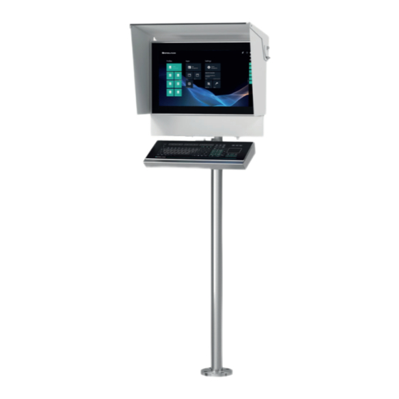
Pepperl+Fuchs VisuNet FLX System Manual

Pepperl+Fuchs VisuNet FLX System Manual

Extended temperature range
Hide thumbs Also See for VisuNet FLX System:

Advertisement

Quick Links

VisuNet FLX System
Extended Temperature
Range
RM-320S-*-B-*
PC-320S-*-B-*
DM-320S-*-B-*
Manual

Advertisement

Table of Contents
loading
Need help?

Need help?

Do you have a question about the VisuNet FLX System and is the answer not in the manual?

Questions and answers

Subscribe to Our Youtube Channel

Summary of Contents for Pepperl+Fuchs VisuNet FLX System

  • Page 1 VisuNet FLX System Extended Temperature Range RM-320S-*-B-* PC-320S-*-B-* DM-320S-*-B-* Manual...
  • Page 2 Phone: +49 621 776 - 0 E-mail: info@de.pepperl-fuchs.com North American Headquarters Pepperl+Fuchs Inc. 1600 Enterprise Parkway Twinsburg, Ohio 44087 Phone: +1 330 425-3555 E-mail: sales@us.pepperl-fuchs.com Asia Headquarters Pepperl+Fuchs Pte. Ltd. P+F Building 18 Ayer Rajah Crescent Singapore 139942 Phone: +65 6779-9091 E-mail: sales@sg.pepperl-fuchs.com https://www.pepperl-fuchs.com...
  • Page 3: Table Of Contents

    VisuNet FLX System Contents History of the Manual ....................5 Introduction........................ 6 Content of this Document ................6 Manufacturer ....................6 Target Group, Personnel ................6 Symbols Used ....................7 Product Description ....................8 Overview......................8 Reference Documents ................. 11 Technical Data....................
  • Page 4 VisuNet FLX System Contents Power Connection..................75 5.3.1 Connect the DC Power Cable ................... 75 5.3.2 Connecting the AC Power Supply ..................77 Interfaces ........................80 Computing Unit - Interface connectors .............80 6.1.1 Power Limitations......................80 Installing Peripherals....................81 Mounting the Keyboard ................81 Installing the IDM Zone 2/22 Barcode Reader...........85...
  • Page 5: History Of The Manual

    VisuNet FLX System History of the Manual History of the Manual The following editions of the manual have been released: Version Comments 11/2023 First edition...
  • Page 6: Introduction

    VisuNet FLX System Introduction Introduction Content of this Document This document contains information that you need in order to use your product throughout the applicable stages of the product life cycle. These can include the following: • Product identification •...
  • Page 7: Symbols Used

    VisuNet FLX System Introduction Symbols Used This document contains symbols for the identification of warning messages and of informative messages. Warning Messages You will find warning messages, whenever dangers may arise from your actions. It is mandatory that you observe these warning messages for your personal safety and in order to avoid prop- erty damage.
  • Page 8: Product Description

    With the modern, compact design less installation space is required. The low weight allows a cost effective and easy installation. In addition, individual solutions can also be created and manufactured at Pepperl+Fuchs' Solu- tion Engineering Centers (SEC), which are located around the world. For example, a large selection of already qualified control elements (e.g.
  • Page 9 VisuNet FLX System Product Description VisuNet FLX System Components Figure 3.1 Component Display Unit: 21.5" display, touch screen, hardened front glass, available with optical bonding or non- optical bonding. RAM / Storage: RAM available as 4 GB, 8 GB and 16 GB DDR4-2133 Storage available as 32 GB, 256 GB and 512 GB, expandable with qualified Pep- perl+Fuchs components.
  • Page 10 VisuNet FLX System Product Description VisuNet FLX pedestal mounted with keyboard/mouse Figure 3.2 VisuNet FLX mounted into AG-3200-*-Housing on a pedestal PEDESTAL-3200-* with adapter and optional EXTA4-* keyboard/mouse (ordered separately) Note For a description of the product model nomenclature, see the VisuNet FLX RM, VisuNet FLX PC or VisuNet FLX DM product datasheets at www.pepperl-fuchs.com.
  • Page 11: Reference Documents

    VisuNet FLX System Product Description Reference Documents Important Instructions and Manuals for Operating the Device Documentation Contents VisuNet FLX • Panel installation Panel • Information regarding 21.5", 19" and 15.6" DPU manual • Connecting the BPC3200-* to the DPU3200-* •...
  • Page 12 VisuNet FLX System Product Description Documentation Contents RM Shell 6 • Overview manual • App Management • System Settings • Factory Reset • How-tos EXTA4-* • Product description manual • Installation and Commissioning • Chemical Resistance Wired handheld • System Structure barcode reader •...
  • Page 13: Technical Data

    Storage: 64 GB M.2 SATA 3, wide temperature grade Software Operating system Pepperl+Fuchs VisuNet RM Shell 6 (based on Microsoft® Win- dows® 10 IoT Enterprise 2021 LTSC (x64)) Optional: T: ACP ThinManager Ready BIOS [Celeron, 4 GB RAM, no stor-...
  • Page 14 VisuNet FLX System Product Description The measurements occurred under the following conditions: Maximum load: • Computing Unit: full load • 11.5 W total electrial loads • Display Unit (21.5") • External Monitor RM-320S-* and PC-320S-* Supply Power consumption Intel® Celeron...
  • Page 15 1 x DisplayPort 1.2 (DP++) 1 x mini DisplayPort 1.2 (DP++ w/ mono locking screw) 1 x Audio Line-out 2 x USB Ex i ports prepared for Pepperl+Fuchs intrinsically safe keyboard 2 x USB 3.1 Gen1 (5 Gbps) ports 1 x USB 2.0 port...
  • Page 16 VisuNet FLX System Product Description International approvals UL approval Approved for UL OrdLoc UL approval E223772 UL61010-1 Ed.3 UL 61010-2-201 Ed2 CAN/CSA C22.2 No 61010-1-12 CAN/CSA C22.2 No 61010-2-201 UL HazLoc UL approval E492874 Non-Incendive circuits for CL I, DIV 2, GP A-D...
  • Page 17 VisuNet FLX System Product Description DM-320S-* General specifications Type Direct Monitor Supply Power consumption A: 115/230 V a.c. (100 ... 240 V a.c.), max. 0.4 A, max. 40 W For detailed information refer to the PSU PS1000-A6-24.5 man- ual. D: 20 ... 28 V d.c. / 1.5 A (SELV/PELV or NEC class 2)
  • Page 18 VisuNet FLX System Product Description Directive conformity Directive 2014/34/EU EN IEC 60079-0:2018 EN IEC 60079-7:2015/A1:2018 EN 60079-31:2014 RoHS Directive 2011/65/EU EN IEC 63000:2018 (RoHS) Ambient conditions Operating temperature -20 °C ... 50 °C (-4 ... 122 °F) Storage temperature -20 °C ... 65 °C (-4 ... 149 °F) Relative humidity max.
  • Page 19 VisuNet FLX System Product Description International approvals ATEX marking II 3 G Ex ec [ic] IIC T4 Gc II 3 D Ex tc IIIC T85°C Dc IECEx approval IECEx certificate IECEx ULD 22.0019X IECEx marking Ex ec IIC T4 Gc Ex tc IIIC T85°C Dc...
  • Page 20: Dimensions And Nameplates

    VisuNet FLX System Product Description Dimensions and Nameplates Dimensions Figure 3.3 0° tilted with pedestal, Dimensions with Top, Sides, Back shields...
  • Page 21 VisuNet FLX System Product Description Figure 3.4 0° tilted with pedestal, Dimensions with Top and Back shields...
  • Page 22 VisuNet FLX System Product Description Wall Bracket Figure 3.5 Dimensions Wall Mounting Note For detailed specification on the VisuNet FLX Panel Mount refer to the VisuNet FLX Panel Mount manual (RM-320P-*, PC-320P-* and DM-320P-*).
  • Page 23 VisuNet FLX System Product Description Nameplates and Labels The following nameplates and labels are attached to the VisuNet FLX System: Figure 3.6 (1) Main Label Figure 3.7 (2) Hot surface! Figure 3.8 (3) Do not open when energized! Figure 3.9...
  • Page 24 VisuNet FLX System Product Description (4) Sublabel BPC3200-* Figure 3.10 (5) Equipotential Bonding Figure 3.11 (6) AC warning Figure 3.12 (7) PE Symbol (Optional with AC configuration) Figure 3.13...
  • Page 25 VisuNet FLX System Product Description (8) Warning! Danger of hand injury! Figure 3.14...
  • Page 26: Mechanical Installation

    The use of the device is only permitted under the ambient conditions (temperature, humidity, vibration and shock) which are specified in the technical data. Failure to comply with any of these conditions void the warranty for the device. Pepperl+Fuchs cannot be held liable for any damage arising from improper use and handling.
  • Page 27: General Installation Information

    Explosion protection is no longer ensured if a system with damaged seals is used. Never use a system with damaged seals in a hazardous area. If the seal is damaged in any way, return the system to Pepperl+Fuchs at once and replace it with a new one. Caution! If the device is facing west, direct sunlight when the sun is setting can penetrate the display with a high ambient temperature.
  • Page 28 VisuNet FLX System Mechanical Installation Figure 4.1 Adapter, pedestal and peripherals as keyboard must be ordered separately Included with Delivery • Preassembled VisuNet RM-, PC- or DM- FLX System, pre-mounted into AG-3200-* hous- • 1x Field Connector RJ45 (must be assembled by customer) Figure 4.2...
  • Page 29: Space Requirements

    VisuNet FLX System Mechanical Installation Figure 4.3 Sleeves • 6x long threaded sleeves (4 are already in use to fix the housing) • 8x short threaded sleeves • 14x M16 blind plugs with sealing • DC terminal block in case of DC configuration Items Ordered Separately •...
  • Page 30 VisuNet FLX System Mechanical Installation Figure 4.4 Caution! Scratches and damage! VisuNet FLX components may become scratched or damaged if they are placed onto or slid across hard surfaces. Caution! Placing the device on the front can damage operating elements! If you place the unit on its front before or during installation, the front panel controls may be damaged.
  • Page 31: Preparing For Pedestal Installation

    VisuNet FLX System Mechanical Installation Preparing for Pedestal Installation For floor mounting, the preferred installation option uses PEDESTAL-3200-* with either two or three cable glands. The pedestal is shipped with a pre-installed rotating coupling with four bolts and a PB wire, which is attached to the pedestal tube.
  • Page 32: Mounting The Housing Onto The Pedestal

    VisuNet FLX System Mechanical Installation Installing the Adapter to the Pedestal Remove the cover of the adapter plate. Align the pedestal centrally – determine the center by turning it to the right and left stop. Then align it at right angle to cable glands at the bottom of the pedestal.
  • Page 33 VisuNet FLX System Mechanical Installation Attaching Housing to Pedestal Carefully turn the housing so that the display is facing up. Using a crane or with the help of another person, place the housing onto the adapter so that the System Housing bolts align with the adapter slots and the housing rests on the adapter. Tighten the M5 washers onto the system housing bolts in a criss-cross pattern using a torque of 2.3...
  • Page 34: Mounting The Housing With 0° Tilted Mounting Adapter

    VisuNet FLX System Mechanical Installation Mounting the Housing with 0° Tilted Mounting Adapter When using the 0° mounting adapter, a 70 mm bolt is required on the lower position to enable mounting. Please replace one of the 6 bolts with the shorter bolt as illustrated.
  • Page 35: Open The Housing

    Mechanical Installation Open the Housing Opening the VisuNet FLX System AG-3200-* Housing Remove the 4 threaded sleeves from the back of the housing. Remove the DPU from the housing and carefully lock the retaining feet on the lower part of the housing into the brackets provided.
  • Page 36 VisuNet FLX System Mechanical Installation Figure 4.9 Tip the display panel toward you until the display comes to rest at its fully opened position and the safety lines are stretched out.
  • Page 37 VisuNet FLX System Mechanical Installation Figure 4.10 The safety lines hold the display when fully extended...
  • Page 38: Installing Cables In The Pedestal

    VisuNet FLX System Mechanical Installation Installing Cables in the Pedestal Warning! Pinched cables! Ensure that cables do not get pinched or damaged during installation. Note Refer to the manuals of the individual components for information on electrical installation and wiring.
  • Page 39 VisuNet FLX System Mechanical Installation Figure 4.12 Pedestal with three Cable Glands Opening size Opening/Wrench Size, Cable Diameter, and Torque Wrench size Cable diameter Torque 24 mm 7 .. 12 mm 10 Nm 20 mm 3 ... 7 mm 5 Nm 20 mm 6 ...
  • Page 40 VisuNet FLX System Mechanical Installation Installing Cables Based on how many cables and openings are required (i.e., power and Ethernet), remove the appropriate number of cable glands at the bottom of the pedestal. Figure 4.13 Put the gland nut and ferrule of the cable gland on the cable and slide them a few meters down the length of the cable away from the pedestal.
  • Page 41 VisuNet FLX System Mechanical Installation Figure 4.15...
  • Page 42 VisuNet FLX System Mechanical Installation Pull the cable through the pedestal so that 50 cm of the cable is hanging out of the top of the pedestal. Figure 4.16 Repeat the preceding steps for each cable that must be routed through the pedestal.
  • Page 43 VisuNet FLX System Mechanical Installation Figure 4.17 Description Size Dual Ethernet M16 (Ø 6-10 mm) Dual Ethernet M16 (Ø 3-7 mm) Power M20 (Ø7-12mm) Spare for additional M20 (Ø7-12mm) connection Note To get the cables through the cable glands, the insulation must be in place. Remove the...
  • Page 44: Closing The Ag-3200-* Housing

    VisuNet FLX System Mechanical Installation Note Cables must be long enough to pull in a loop, before fixation. Figure 4.18 Note For detailed information on the equipotential bonding of the device refer to chapter Equipotential Bonding. For detailed information on connecting the installed cables to system refer to chapter Interfaces of the system.
  • Page 45 VisuNet FLX System Mechanical Installation Optional: Use the Spare Part Housing Blind Plugs for Strict GMP Requirement SPAREPART-AG-320S-BP-P1 (#70136529) Follow above mentioned steps 1 to 5. Screw the pharma blind plugs with the seal into the housing. Figure 4.19 Tighten them all up with a torque of 2 Nm.
  • Page 46: Wall Mount Installation

    VisuNet FLX System Mechanical Installation Figure 4.20 Caution! Foreign bodies! Keep the housing doors and openings permanently closed, so that no foreign bodies accumu- late in the workstation. Wall Mount Installation Warning! Proper installation on the wall! It is the installer's responsibility to select a suitable location with sufficient strength to hold the device.
  • Page 47: Wall Mounting For Scanner Barrier

    VisuNet FLX System Mechanical Installation Wall Mounting Use the hole pattern to install the bracket to the wall. Connect the PB wire from the field to the PB stud on the wall bracket. Mount the VisuNet FLX to the bolts on the wall bracket. With the DPU hinged down, route cables through the cable glands in the wall bracket.
  • Page 48 VisuNet FLX System Mechanical Installation Remove cover. Figure 4.22 Remove M16 blind plug. In same hole, install the M12 socket. Tighten the M12 socket with 0.6 Nm. The lock nut of the coupling in the adapter with 2 Nm. Install ground cable in position shown.
  • Page 49 VisuNet FLX System Mechanical Installation Remove cable gland No 4 (M20 Ø7-12 mm). By this point, the DPU should be in the open position. Fix the integrated cable gland of the supply cable in the section that has become free. Fix it with...
  • Page 50 VisuNet FLX System Mechanical Installation Connect the M12 plug of the supply cable to the connector in the adapter and tighten it firmly. Figure 4.24 Bend the cable as shown in the following picture. Figure 4.25...
  • Page 51 VisuNet FLX System Mechanical Installation Warning! Bending radius must be maintained. The minimum allowed bending radius is Ø80mm. Place the USB supply cable with the Velcro tape on the left side of the inner side of the adapter. Connect the USB connector of the supply cable to the BPC3200-*.
  • Page 52 VisuNet FLX System Mechanical Installation Position of barrier inside back surface of adapter: Figure 4.27 Connect the plug of the barcode reader connection cable or base station connection cable to the M12 connector of the adapter and tighten it firmly.
  • Page 53 VisuNet FLX System Mechanical Installation Figure 4.29 After mounting the adapter for the VisuNet FLX it should look like this: Figure 4.30...
  • Page 54: Top Sunshield Installation Instructions

    VisuNet FLX System Mechanical Installation 4.11 Top sunshield installation instructions Follow the installation instructions see chapter 4.1 to avoid damage to the device. Note If only using the top sunshield it is recommended to rotate the top sunshield down when not in use to ensure further protection of the device.
  • Page 55 VisuNet FLX System Mechanical Installation Pre-assemble the top sunshield as shown in the figure. Figure 4.32 Items for the pre-installation of the top sunshield Item Description Part-No. Sunshield top Sunshield Mounting Bracket, left Sunshield Mounting Bracket, right Washer, M8 oversized 126822...
  • Page 56 VisuNet FLX System Mechanical Installation Tighten the M8 lock nuts (item nr. 5) to keep the top shield in place but still allow rotation with some force applied. Align brackets to allow installation of sunshield in closed position. Tighten them so that the brackets provide resistance but still allow some force to be rotated.
  • Page 57 VisuNet FLX System Mechanical Installation Remove the 4 screws and washers from the backside of the housing as shown. Figure 4.34...
  • Page 58 VisuNet FLX System Mechanical Installation Carefully fit pre-assembled top sunshield over top of outer housing and install and tighten the 4 screws to a torque of 4 Nm. Figure 4.35 Rotate sunshield top into desired operating position and firmly hand tighten knob.
  • Page 59: Side, Top And Back Sunshield Installation Instructions

    VisuNet FLX System Mechanical Installation 4.12 Side, top and back sunshield installation instructions Figure 4.36 Pre-assemble the top sunshield as shown in the figure. Figure 4.37 Item Description Part-No. Sunshield top Sunshield Mounting Bracket, left Sunshield Mounting Bracket, right M8 lock nut...
  • Page 60 VisuNet FLX System Mechanical Installation Item Description Part-No. Washer, M8 flat 522104 Edge protector 523747 Tighten the M8 lock nuts (item nr. 4) to keep the top shield in place but still allow rotation with some force applied. Align brackets to allow installation of sunshield in closed position. Tighten them so that the brackets provide resistance but still allow some force to be rotated.
  • Page 61 VisuNet FLX System Mechanical Installation Remove the screws and washers from backside of housing as shown. Figure 4.39...
  • Page 62 VisuNet FLX System Mechanical Installation Carefully fit pre-assembled top sunshield over top of outer housing and install and tighten the 4 screws to a torque of 4 Nm. Figure 4.40 Install the 2 female-female spacers to mounting brackets and tighten to a torque of 3 Nm.
  • Page 63 VisuNet FLX System Mechanical Installation Item No. Part-Nr. Description Torque (Nm) 112373 M5x12 Socket Head Cap Screw 70171760 M5x15mm, F-F Space 70171761 M5x15mm, M-F Spacer Install the 2 female-male spacers to outer housing and tighten to a torque of 4 Nm.
  • Page 64 VisuNet FLX System Mechanical Installation Align back shield with the 4 screws with the keyhole slots and set into place. Figure 4.43 Tighten the 4 screws to a torque of 2.3 Nm. Note If side shields will be installed skip the next step.
  • Page 65 VisuNet FLX System Mechanical Installation The sunshield top and back assembly is now complete. Figure 4.44 Rotate top shield as shown until the side hole aligns with the screw mounting hole. Temporarily tighten nuts in slotted holes to hold the top shield in position.
  • Page 66 VisuNet FLX System Mechanical Installation Position the right sideshield as shown by sliding into position between the top sunshield and the right mounting bracket. Rotate the side sunshield clockwise until the holes are aligned with the screw threads on the mounting brackets.
  • Page 67: Back-Only Sunshield Installation Instructions

    VisuNet FLX System Mechanical Installation 4.13 Back-only sunshield installation instructions Remove the 6 screws and washers from the backside of the housing. Figure 4.47 Install the left and right mounting brackets to the back of the outer housing and install and tighten the 4 screws to a torque of 4 Nm.
  • Page 68 VisuNet FLX System Mechanical Installation Figure 4.48 Tighten the 4 screws to a torque of 2.3 Nm. The back sunshield assembly is now complete.
  • Page 69: Electrical Installation

    Ensure that external equipotential bonding connections exist, are in good condition, and are not damaged or corroded. Danger! When installing the VisuNet FLX system, always ensure a proper equipotential bonding of all components, including housing and mounting parts (e.g., pedestal and wall bracket) with a cable diameter of at least 4 mm (~12-24 AWG) in accordance with IEC 60079-14.
  • Page 70: Equipotential Bonding

    Electrical Installation Equipotential Bonding When installing the VisuNet FLX system, always ensure that all components are properly con- nected with equipotential bonding (PB), including housing and mounting parts (e.g., pedestal and wall bracket) with a cable diameter of at least 4 mm (~12-24 AWG) in accordance with IEC 60079-14.
  • Page 71: Equipotential Bonding Connection Of The Housing To The Pedestal

    VisuNet FLX System Electrical Installation 5.2.1 Equipotential Bonding Connection of the Housing to the Pedestal When the AG-3200-* housing option is selected, the VisuNet FLX is shipped with the following PB connections: PB wire from the adapter plate (1) to a lens head screw of the panel (2) and an extra PB wire to the computing platform housing (3).
  • Page 72 VisuNet FLX System Electrical Installation Figure 5.3 Warning! PB protective equipotential bonding! PB protective equipotential bonding is mandatory. Warning! Operator responsibility to verify PB protective equipotential bonding! Check the PB protective equipotential bonding after completing system installation. Warning! Risk of personal injury and equipment damage! Pinched PE wire Ensure that the PE wire does not become pinched between the pedestal and housing.
  • Page 73 VisuNet FLX System Electrical Installation Equipotential bonding connection the AG-XX00 Housing to PEDESTAL- AG3200-* The pedestals come with a preinstalled equipotential bonding cable. Warning! This is not valid if you use an already installed/old VisuNet pedestal. Refer to the corresponding manual.
  • Page 74: Equipotential Bonding Of The Pedestal

    VisuNet FLX System Electrical Installation 5.2.2 Equipotential bonding of the pedestal Procedure Connect the equipotential bonding of the pedestal with the PB stud on the bottom plate of PEDESTAL-AG-3200-* Fasten the hardware with a torque of 7,5 Nm. Figure 5.5 The vertical stand provides on the base plate a grub screw for the connection of an equipoten- tial bonding conductor.
  • Page 75: Power Connection

    VisuNet FLX System Electrical Installation Power Connection Warning! Hazard due to excessive current! Excessive current can cause overloading of the electronics which could then result in injury or damage. Operate the device with a power supply that complies with SELV/PELV or NEC Class 2! 5.3.1...
  • Page 76 VisuNet FLX System Electrical Installation Wiring and Connecting the Terminal Block Field Input Remove the terminal block from the computing unit and connect the power cable to the terminal block with a torque of 0.5 - 0.6 Nm. Figure 5.7 Pin No.
  • Page 77: Connecting The Ac Power Supply

    VisuNet FLX System Electrical Installation Figure 5.9 5.3.2 Connecting the AC Power Supply If the VisuNet FLX is configured with AC/DC power supply, the Power supply unit is preinstalled in the system. AC-Power Supply Figure 5.10 PS1000-A6-24.5...
  • Page 78 VisuNet FLX System Electrical Installation Figure 5.11 Front view The following table contains the technical characteristics of the AC power supply module: Figure 5.12...
  • Page 79 VisuNet FLX System Electrical Installation Wiring and Connecting the PS1000-A6-24.5 Field Input Figure 5.13 Wiring Allowed cable diameter AWG 16 bis AWG 12 (1.5 mm²...4 mm²) Warning! All three wires must be connected! For further information regarding the AC power supply module refer to PS1000-A6-24.5 man-...
  • Page 80: Interfaces

    For this purpose, the maximum operating conditions (maximum operating temperature at maximum load) are considered. It is absolutely necessary to consider maximum allowed output currents when installing the Vis- uNet FLX in Zone 2/22 environment. Maximum output currents VisuNet FLX system installation Port System USB 2.0...
  • Page 81: Installing Peripherals

    VisuNet FLX System Installing Peripherals Installing Peripherals Warning! Disconnect the entire power supply to the device before removing covers or components of the system and install/remove accessories, hardware or cables. Mounting the Keyboard The EXTA4-* is the system keyboard/mouse available with a mounting option for the VisuNet...
  • Page 82 VisuNet FLX System Installing Peripherals Mounting the EXTA4-* Keyboard to VisuNet FLX Housing Mechanical Installation description Open and remove the four cover plate screws on the bottom-left side of the AG-3200 housing. Figure 7.1 Route the keyboard cable with the USB connectors through the hole of the AG-3200 housing.
  • Page 83 VisuNet FLX System Installing Peripherals Using the screws and lock washers delivered with the EXTA4-*-H1-* keyboard, attach the keyboard to the AG-3200 housing. Fasten the four screws with a torque of 6 Nm. Connect the USB connectors to the USB Ports of the BPC3200-*.
  • Page 84 VisuNet FLX System Installing Peripherals Figure 7.2 Figure 7.3...
  • Page 85: Installing The Idm Zone 2/22 Barcode Reader

    VisuNet FLX System Installing Peripherals Installing the IDM Zone 2/22 Barcode Reader Mounting the IDM-* Barcode Reader Holder Bracket SCANNER-HOLDER-U1-3200-N0 is a holder for the IDM-* handheld barcode reader family. The holder is compatible with the VisuNet FLX housing. Required Components •...
  • Page 86 VisuNet FLX System Installing Peripherals Mounting SCANNER-HOLDER-U1-3200-N0 to AG-3200 Housing Remove the blind plugs on the right site of the back of the housing Figure 7.5...
  • Page 87 VisuNet FLX System Installing Peripherals Connect the scanner holder with the enclosed screws by pressing it against the housing from the outside and fasten the screws using a torque of 4 Nm. Figure 7.6...
  • Page 88 VisuNet FLX System Installing Peripherals Figure 7.7...
  • Page 89 VisuNet FLX System Installing Peripherals Follow the same steps to mount HOLDER-BRACKET-3200-IDMx61-B-N (#70129841). This bracket holds the IDM base station. Figure 7.8...
  • Page 90 VisuNet FLX System Installing Peripherals Figure 7.9...
  • Page 91 VisuNet FLX System Installing Peripherals Cable installation for IDM Zone 2/22 Barcode Readers and Base Stations For the installation of the IDM barcode readers the USB supply cable SK-IDM-Z2-J2-1M-U-N is necessary. Required Components • ADAPTER-3200-10-304B-M12 • KIT-IDM-Z2-USB-N0 • SK-IDM-Z2-J2-1M-U-N USB supply cable •...
  • Page 92 VisuNet FLX System Installing Peripherals USB Supply cable SK-IDM-Z2-J2-1M-U-N Figure 7.10 Supply cable for wired barcode readers IDM-Z2-160-D-* and base station IDM-Z2-x60- D-* with USB connection - IDM barcode reader connection via M12 connector. Note Supports only USB barcode reader / base station...
  • Page 93 VisuNet FLX System Installing Peripherals Installing the supply cable SK-IDM-Z2-J2-1M-U-N Open the housing. See chapter 4.5 and open die back plate of the adapter. Fix the M12 connector in the hole of the adapter. Tighten the M12 socket with 0.6 Nm. The lock nut of the coupling in the adapter with 2 Nm.
  • Page 94 VisuNet FLX System Installing Peripherals After installing the Ethernet and Power cables, remove cable gland N° 4 (M20 Ø7-12 mm) Figure 7.12 Fix the integrated cable gland of the supply cable in the section that has become free. Fix it with a torque of 10 Nm.
  • Page 95 VisuNet FLX System Installing Peripherals Figure 7.14 Connect the M12 plug of the supply cable to the connector in the adapter and tighten it firmly.
  • Page 96 VisuNet FLX System Installing Peripherals Bend the cable as shown in the following graph. Figure 7.15 Figure 7.16...
  • Page 97 VisuNet FLX System Installing Peripherals Warning! Bending radius must be maintained. The maximum allowed bending radius is 80°. Figure 7.17 Place the USB supply cable with the Velcro tape on the left side of the inner side of the adapter.
  • Page 98 VisuNet FLX System Installing Peripherals Figure 7.19 Use the cable clamp of the KIT-IDM-Z2-USB-N0 and cable ties to route the supply cable as shown in the following graph. Warning! Bending radius must be maintained. The maximum allowed bending radius is 80°.
  • Page 99 VisuNet FLX System Installing Peripherals Connect the plug of the barcode reader connection cable or base station connection cable to the M12 connector of the adapter and tighten it firmly. Figure 7.21 Coded Plug and Socket Figure 7.22 The plug and socket are coded. Match the coding on the plug and socket before tightening.
  • Page 100: Installing The Bluetooth®-Kit

    VisuNet FLX System Installing Peripherals Installing the Bluetooth®-Kit Warning! When the Bluetooth Kit is installed, the VisuNet FLX System is certified for ATEX and IECEx Zone 2/22 installations, not for use in Div. 2. Optional Bluetooth® Installation: Note Steps 1 to 4 are obsolete if your VisuNet FLX has already a preinstalled Bluetooth® dome.
  • Page 101 VisuNet FLX System Installing Peripherals Loosen the wing nut inside either with pliers or your hands. Figure 7.24 Remove the cover and the seal from the inside.
  • Page 102 VisuNet FLX System Installing Peripherals Insert the black Bluetooth® dome and lock it with enclosed nut: a) Make sure that the locking lug is in the right position. b) Use a socket wrench to fix the nut. Figure 7.25...
  • Page 103 VisuNet FLX System Installing Peripherals Attach the prepared Bluetooth® assembly (dongle+holder+cable) and snap it into place by turning clockwise. Figure 7.26 Plug the USB cable into the BPC. Software: No additional driver is necessary for the Bluetooth® application. Open the Windows® Dialog and follow the steps to pair the devices.
  • Page 104: Maintenance, Cleaning And Disposal

    VisuNet FLX System Maintenance, Cleaning and Disposal Maintenance, Cleaning and Disposal All VisuNet FLX models perform a degree of thermal management to avoid overheating under heavy load. The VisuNet FLX devices have an internal temperature sensor, which software on the GPU polls to ensure that temperatures do not exceed a predefined limit.
  • Page 105: Dismounting The Display Unit

    VisuNet FLX System Maintenance, Cleaning and Disposal 8.2.1 Dismounting the Display Unit If repairs are required, the DPU can be dismounted from the BPC3200-* or DMU3200-* and be replaced. Warning! Danger of Explosion! An ignition may be triggered if the BPC3200-* or DMU3200-* is still energized when its terminal compartment is opened.
  • Page 106 VisuNet FLX System Maintenance, Cleaning and Disposal Figure 8.2 Remove all 4 screws from the back of the BPC3200-*/DMU3200-* and take it off the DPU Figure 8.3 To simplify replacement of the DPU, temporarily hold the BPC3200-*/DMU3200-* in place using cable ties. Put cable ties through both mounting holes at the top-left and top-right corners, and hang the BPC3200-*/DMU3200-* from the top of the housing frame.
  • Page 107 VisuNet FLX System Maintenance, Cleaning and Disposal Remove PB and cable ties. Now the DPU can be removed from the housing. During the removal process, hold the DPU steady so it cannot fall down, preferably with the help of another person. Place the DPU on an even, cushioned surface after removal.
  • Page 108: Exchanging The Psu

    VisuNet FLX System Maintenance, Cleaning and Disposal 8.2.2 Exchanging the PSU Procedure Remove the connected field input cables from the PSU. Remove the metal holder from the system. Figure 8.6 Remove the output cables from the PSU. Remove the PSU from the metal holder.
  • Page 109: Exchanging The Bpc3200-* Or Dmu3200

    VisuNet FLX System Maintenance, Cleaning and Disposal Exchanging the BPC3200-* or DMU3200-* Procedure Open the AG-3200-* housing. See chapter 4.5 Open the Housing. After de-energizing (see above), open the terminal compartment of the TCU/PCU/DMU. Please refer to the VisuNet FLX Panel Mount manual chapter 7.1 for detailed information. From step 2 you will find all relevant information.
  • Page 110: Chemical Resistance

    VisuNet FLX System Chemical Resistance Chemical Resistance The VisuNet FLX HMI product line is made of different materials that have different characteris- tics in terms of chemical resistance. Main materials that are used in this product line include: • Hardened glass (Display cover glass) •...
  • Page 111 VisuNet FLX System Chemical Resistance The chemical resistance of materials highly depends on various factors, including exposure time, temperature, humidity etc. and can lead to different forms of product alterations including discoloration, change in shore, tearing strength, volume etc. The above listed materials have been assessed against following chemicals using an immer- sion test (min.
  • Page 112 VisuNet FLX System Chemical Resistance Note Cosmetic (e.g. discoloration, change of surface structure) and/or temporary alterations that have no impact on the product functionality (e.g. ingress protection) and/or safety are not considered as a relevant reduction of the product quality.
  • Page 113: Appendix

    VisuNet FLX System Appendix Appendix Figure 10.1 VisuNet FLX System - possible configurations Spare Parts Type code Item No. Description DPU3200-22GT-304A-V1- 70128300 21.5" Display (Full HD) - Display option "22GT" with capacitive touch screen DPU3200-22FC-304A-V1- 70128301 21.5" Display (Full HD), optically bonded - Display option "22FC"...
  • Page 114 VisuNet FLX System Appendix Mounting and Installation Type code Item No. Description ADAPTER-3200-00-304B- 70129832 0° tilted adapter for pedestal, wall arm, ceiling mounting for AG-3200-* housing Surface finish: brushed (Ra <= 0.8 μm) incl. mounting material to fix adapter to...
  • Page 115 - Consists of USB stick, cable and mount- ing adapter - Bluetooth® standards: v4.0 (and back- wards compatible) - Certification: CE, FCC and others - Prepared for mounting into VisuNet FLX system housing Note For more options and accessories, contact your local Pepperl+Fuchs sales representative.
  • Page 116 Pepperl+Fuchs Quality Download our latest policy here: www.pepperl-fuchs.com/quality www.pepperl-fuchs.com © Pepperl+Fuchs · Subject to modifications / DOCT-9011...

Table of Contents

Save PDF