
Subscribe to Our Youtube Channel
Related Manuals for Pepperl+Fuchs IC-KP2-2HB21-2V1D


Summary of Contents for Pepperl+Fuchs IC-KP2-2HB21-2V1D
- Page 1 FACTORY AUTOMATION MANUAL IC-KP2-2HB21-2V1D IDENTControl Compact control interface with interface for EtherCAT...
- Page 2 IC-KP2-2HB21-2V1D With regard to the supply of products, the current issue of the following document is applicable: The General Terms of Delivery for Products and Services of the Electrical Industry, published by the Central Association of the Electrical Industry (Zentralverband Elektrotechnik und Elektroindustrie (ZVEI) e.V.) in its most recent version as well as the supplementary clause: "Expanded reservation...
-
Page 3: Table Of Contents
IC-KP2-2HB21-2V1D Contents 1 Introduction................. 5 EtherCAT ......................5 2 Declaration of conformity ..........6 CE conformity ....................6 3 Safety ................... 7 Symbols relevant to safety ................7 Intended Use ....................7 General notes on safety.................7 Contact protection..................8 4 Product Description ............9 Product family ....................9 4.1.1 R/W heads ....................9... - Page 4 IC-KP2-2HB21-2V1D Contents 6 Commissioning ..............21 Connection....................21 Device settings................... 21 6.2.1 Address setting ..................21 6.2.2 Non-volatile parameters................. 21 7 Commands................ 22 General Information about EtherCAT ............22 Communication via EtherCAT ..............22 7.2.1 Data Flow Control .................. 24 7.2.2 Command Information ................
-
Page 5: Introduction
Introduction Introduction Congratulations You have chosen a device manufactured by Pepperl+Fuchs. Pepperl+Fuchs develops, produces and distributes electronic sensors and interface modules for the market of automation technology on a worldwide scale. Before you install this device and put it into operation, please read the operating instructions thoroughly. -
Page 6: Declaration Of Conformity
IC-KP2-2HB21-2V1D Declaration of conformity Declaration of conformity CE conformity This product was developed and manufactured under observance of the applicable European standards and guidelines. Note! A declaration of conformity can be requested from the manufacturer. -
Page 7: Safety
If serious faults occur, stop using the device. Secure the device against inadvertent operation. In the event of repairs, return the device to your local Pepperl+Fuchs representative or sales office. The connection of the device and maintenance work when live may only be carried out by a qualified electrical specialist. -
Page 8: Contact Protection
IC-KP2-2HB21-2V1D Safety Store the not used device in the original packaging. This offers the device optimal protection against impact and moisture. Ensure that the ambient conditions comply with regulations. Note! Disposal Electronic waste is hazardous waste. When disposing of the equipment, observe the current statutory requirements in the respective country of use, as well as local regulations. -
Page 9: Product Description
Read/write tags in this frequency range save larger quantities of data and offer a considerably higher reading speed than read/write tags of the 125 kHz system. IQH-* and IQH1-* read/write heads from Pepperl+Fuchs are compatible with most existing read/write tags that comply with standard ISO 15693. With the IQH2-* read/write heads you can use read/write tags that comply with standard ISO 14443A. -
Page 10: Handhelds
IC-KP2-2HB21-2V1D Product Description Data carrier 868 MHz (UHF) Data carriers in this frequency range can be passive as well as active (with battery) and use a specially-shaped rod antenna as the resonance element. The passive transponders can be produced very cheaply and have a range of several meters. -
Page 11: Connection Accessories
IC-KP2-2HB21-2V1D Product Description Connection accessories 4.2.1 Connection cable for R/W heads and trigger sensors Compatible connection cables with shielding are available for connecting the R/W heads and trigger sensors. Figure 4.2 Accessories Description 2 m long (straight female, angled male) -
Page 12: Cable Connectors For The Power Supply
IC-KP2-2HB21-2V1D Product Description 4.2.2 Cable connectors for the power supply Compatible M12 sockets with an open cable end for connecting the IDENTControl Compact to a power supply are available in different lengths. Figure 4.3 Accessories Model number Length 2 m (straight socket) -
Page 13: Adapter For Rs 232 Diagnostic Interface
IC-KP2-2HB21-2V1D Product Description 4.2.4 Adapter for RS 232 diagnostic interface A compatible adapter is available for connecting the IDENTControl Compact to the RS 232 diagnostic interface for diagnosis. Figure 4.5 Accessories Designation M8 to SUBD adapter V3S-GM-0.15M-PUR-ABG-SUBD 4.2.5 Mounting aid An aid for mounting the IDENTControl Compact to a DIN mounting rail is available. -
Page 14: Device Characteristics
IC-KP2-2HB21-2V1D Product Description Device characteristics Up to 2 R/W heads can be connected ■ Alternatively, 1 R/W head and 1 trigger sensor can be connected ■ LED status indicators for bus communication and R/W heads ■ Interfaces and connections The control interface IC-KP2-2HB21-2V1 has the following interfaces and... -
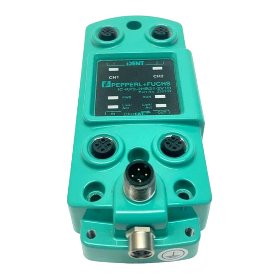
Page 15: Displays And Controls
IC-KP2-2HB21-2V1D Product Description Displays and Controls Link/ Link/ Figure 4.7 LEDs Description Function Status description Status display for LED lights up green when there is an active read/write heads command on the read/write head. LED illuminates yellow for approx. 1 second when a command has been successfully executed. -
Page 16: Installation
■ Retain the original packaging in case you have to store or ship the device again at a later date. Should you have any questions, please contact Pepperl+Fuchs. EMC concept The outstanding noise immunity of the IDENTControl Compact against emission and immission is based on its consistent shielding design, which uses the principle of the Faraday cage. -
Page 17: Device Connection
IC-KP2-2HB21-2V1D Installation The metal enclosure of the IDENTControl Compact and the metal enclosure of the R/W heads complete the consistent shielding concept. You must establish a low resistance and low inductance connection between the shields and ground so that the shielding is not interrupted through the metal enclosure. -
Page 18: Ground Connection
IC-KP2-2HB21-2V1D Installation Connecting R/W heads Connect the R/W heads or the trigger sensor with compatible cable to the top of the enclosure via the M12 connector. 5.3.3 Ground connection Connect the IDENTControl Compact unit to ground via a screw on the right under the housing. - Page 19 IC-KP2-2HB21-2V1D Installation Connector assignment Signal Use the adapter V3S-GM-0.15M-PUR-SUBD to connect the IDENTControl Compact to the RS 232 diagnostic interface. Pin assignment of the adapter for the RS 232 diagnostic interface 6..9 Figure 5.2 Connection example RS 232 Host-PC IDENTControl...
-
Page 20: Ethercat Connection Guide
IC-KP2-2HB21-2V1D Installation 5.3.5 EtherCAT connection guide Use the D-coded M12 socket and the V1SD-G-5M-PUR-ABG-V45-G cable to connect the IDENTControl Compact control interface to an EtherCAT network. Caution! Electromagnetic interference Device malfunction caused by EMC effects. The M12 socket is connected galvanically to the grounded housing. To avoid... -
Page 21: Commissioning
IC-KP2-2HB21-2V1D Commissioning Commissioning Connection Warning! Incorrect electrical connection Incorrect connections may damage the system. When the supply voltage is connected and the device is initialized, the PWR/ERR LED lights up green. If the LED lights up red, either the initialization process has not yet finished or there is a device fault. -
Page 22: Commands
The EtherCAT Technology Group (ETG) publishes various information brochures and an EtherCAT product catalog (http://www.ethercat.org). Communication via EtherCAT In order to integrate the IC-KP2-2HB21-2V1D device in a PLC project, you need the EtherCAT slave information file (ESI file). You can find this ESI file at http://www.pepperl-fuchs.com. - Page 23 IC-KP2-2HB21-2V1D Commands The devices are differentiated by the number of transferable bytes: Channel 0 Channel 1 Channel 2 Device Control interface Reader 1 Reader 2 16 byte IN/OUT 8 byte 16 byte 16 byte 64 byte IN/OUT 8 byte 64 byte...
-
Page 24: Data Flow Control
IC-KP2-2HB21-2V1D Commands INPUT telegram: Byte Content Bit no. Byte 0 Control byte Byte 1 Reserved Byte 2 Command code Byte 3 Reserved Byte 4 Status Byte 5 Reply counter Byte 6 Parameter Byte 7 Parameter Byte 8 Data Data Byte N Data Table 7.2... - Page 25 IC-KP2-2HB21-2V1D Commands DATA Command Enhanced Read (ER) DATA Response to ER T1 T2 T3 T1 The PLC will change the delete bit to high (A) and leads to the deletion of the FIFO mem- ory in the control interface. T2 The control interface will change the delete bit in the input field (B) in response to the event T1 and clears the entire contents of the FIFO memory.
-
Page 26: Command Information
IC-KP2-2HB21-2V1D Commands Master update bit: As soon as a new command is to be sent to the slave, the following instruction must be executed: Write command to the OUTPUT data field: OUTPUT[1..x] := new telegram IF (UM_OUTPUT <> UM_INPUT) then (* check whether the slave can receive... -
Page 27: Command Types
IC-KP2-2HB21-2V1D Commands 7.2.3 Command types When using commands, a distinction is always made between the two command types single mode and enhanced mode. Single mode The command is executed once. A response is issued immediately. Enhanced mode The command remains permanently active until it is interrupted by the user or by an error message. - Page 28 IC-KP2-2HB21-2V1D Commands Write data Command Abbre code Command description viation See "single write words (SW)" on page 43 See "enhanced buffered write words (EW)" on page 44 Special command modes Password mode with IPC03 Command Abbre code Command description viation See "set password mode (PM)"...
- Page 29 IC-KP2-2HB21-2V1D Commands Extended commands for type IDC-...-1K and IQC… tags Command Abbre code Command description viation See "single write words with lock (SL)" on page 71 See "enhanced write words with lock (EL)" on page 72 Extended commands for IQH2-... and IUH-... read/write heads With the commands WriteParam WP and ReadParam RD you can configure the IUH-F117-V1 read/write head using different parameters.
-
Page 30: 04 See "Change Tag (Ct)
IC-KP2-2HB21-2V1D Commands 7.2.5 System commands change tag (CT) Command: Byte Content Bit no. Byte 0 Control byte Byte 1 Reserved Byte 2 Command code - 04 Byte 3 Reserved Byte 4 Tag type in ASCII <TagType> (high byte) Byte 5 Tag type in ASCII <TagType>... - Page 31 IC-KP2-2HB21-2V1D Commands Supported Tag Types Tag type Chip type Access Writable Read Frequency desig- memory only range nation [bytes] code High length byte byte [byte] IPC02 Unique, EM4102 (EM Read only 125 kHz microelectronic) code IPC03 EM4450 (EM Read/write 125 kHz...
- Page 32 The tag type configured in the read/write head as the default is selected. Read/write tags can have 4-byte (older versions) or 7-byte UIDs. IQC42 and IQC43 type read/write tags from Pepperl+Fuchs generally have 7-byte UIDs. Note! In a plant where only one tag type is used, it is advantageous to permanently configure that tag type so that the read/write head detects the tag quicker.
-
Page 33: D 02 H See "Quit (Qu)
IC-KP2-2HB21-2V1D Commands quit (QU) Command: Byte Content Bit no. Byte 0 Control byte Byte 1 Reserved Byte 2 Command code - 02 Byte 3 Reserved Byte 4 Not used Byte 5 Not used Byte 6 Not used Byte 7 Not used... -
Page 34: See "Configuration Store (Cs)
IC-KP2-2HB21-2V1D Commands configuration store (CS) Command: Byte Content Bit no. Byte 0 Control byte Byte 1 Reserved Byte 2 Command code - 17 Byte 3 Reserved Byte 4 Mode <Mode> Byte 5 Not used Byte 6 Not used Byte 7... -
Page 35: 22 D 16 See "Reset (Rs)
IC-KP2-2HB21-2V1D Commands reset (RS) Command: Byte Content Bit no. Byte 0 Control byte Byte 1 Reserved Byte 2 Command code - 16 Byte 3 Reserved Byte 4 Not used Byte 5 Not used Byte 6 Not used Byte 7 Not used This command terminates all active commands. -
Page 36: See "Set Multiplexed Mode (Mm)
IC-KP2-2HB21-2V1D Commands set multiplexed mode (MM): Byte Content Bit no. Byte 0 Control byte Byte 1 Reserved Byte 2 Command code - 9B Byte 3 Reserved Byte 4 Multiplex mode <MultiplexMode> Byte 5 Not used Byte 6 Not used Byte 7... -
Page 37: See "Set Triggermode (Tm)
IC-KP2-2HB21-2V1D Commands set triggermode (TM): Byte Content Bit no. Byte 0 Control byte Byte 1 Reserved Byte 2 Command code - 9C Byte 3 Reserved Byte 4 Trigger mode <Triggermode> Byte 5 Identity channel <Identchannel> Byte 6 Not used Byte 7... - Page 38 IC-KP2-2HB21-2V1D Commands If trigger mode is activated with <Triggermode>=1 (=2), dampening the trigger sensor generates the status 0 (5) and after changing to undamped state, generates the status 5 (0) as a response to <Sensorchannel>. Activating trigger mode generates a response that includes the current status of the sensor on <Sensorchannel>.
-
Page 39: Standard Read/Write Commands
IC-KP2-2HB21-2V1D Commands 7.2.6 Standard read/write commands single read read only code (SF) Command: Byte Content Bit no. Byte 0 Control byte Byte 1 Reserved Byte 2 Command code - 01 Byte 3 Reserved Byte 4 Not used Byte 5 Not used... -
Page 40: See "Enhanced Buffered Read Read Only Code (Ef)
IC-KP2-2HB21-2V1D Commands enhanced buffered read read only code (EF) Command: Byte Content Bit no. Byte 0 Control byte Byte 1 Reserved Byte 2 Command code - 1D Byte 3 Reserved Byte 4 Not used Byte 5 Not used Byte 6... -
Page 41: See "Single Read Words (Sr)
IC-KP2-2HB21-2V1D Commands single read words (SR) Command: Byte Content Bit no. Byte 0 Control byte Byte 1 Reserved Byte 2 Command code - 10 Byte 3 Reserved Byte 4 Word address <WordAddr> (high byte) Byte 5 Word address <WordAddr> (low byte) -
Page 42: See "Enhanced Buffered Read Words (Er)
IC-KP2-2HB21-2V1D Commands enhanced buffered read words (ER) Command: Byte Content Bit no. Byte 0 Control byte Byte 1 Reserved Byte 2 Command code - 19 Byte 3 Reserved Byte 4 Word address <WordAddr> (high byte) Byte 5 Word address <WordAddr> (low byte) -
Page 43: 40 See "Single Write Words (Sw)
IC-KP2-2HB21-2V1D Commands single write words (SW) Command: Byte Content Bit no. Byte 0 Control byte Byte 1 Reserved Byte 2 Command code - 40 Byte 3 Reserved Byte 4 Word address <WordAddr> (high byte) Byte 5 Word address <WordAddr> (low byte) -
Page 44: See "Enhanced Buffered Write Words (Ew)
IC-KP2-2HB21-2V1D Commands enhanced buffered write words (EW) Command: Byte Content Bit no. Byte 0 Control byte Byte 1 Reserved Byte 2 Command code - 1A Byte 3 Reserved Byte 4 Word address <WordAddr> (high byte) Byte 5 Word address <WordAddr> (low byte) -
Page 45: Special Command Modes
IC-KP2-2HB21-2V1D Commands If two tags enter the read range one immediately after the other, the status '05h' is not issued between the two readings. 7.2.7 Special command modes Commands for the data carrier IPC03 Note! You can only use the commands in this section for the data carrier type '03' (IPC03). - Page 46 IC-KP2-2HB21-2V1D Commands Control word Meaning Byte 0 ... 7 Read range start 8 ... 15 Read range end Password mode on/off "Read after write" operating mode on/off 18 ... 23 Open 24 ... 31 Open IPC03 password mode If the password mode in the data carrier is activated, the data range of the data carrier is read and write-protected and can only be read or written if the R/W head sends the correct password to the data carrier.
-
Page 47: 24 D 18 H See "Set Password Mode (Pm)
IC-KP2-2HB21-2V1D Commands set password mode (PM) Command: Byte Content Bit no. Byte 0 Control byte Byte 1 Reserved Byte 2 Command code - 18 Byte 3 Reserved Byte 4 Password mode <PasswordMode> Byte 5 Not used Byte 6 Not used... -
Page 48: 41 See "Change Password (Pc)
IC-KP2-2HB21-2V1D Commands change password (PC) Command: Byte Content Bit no. Byte 0 Control byte Byte 1 Reserved Byte 2 Command code - 41 Byte 3 Reserved Byte 4 Old password 00 ... FF <PSW> (byte 3) Byte 5 Old password 00 ... FF <PSW>... -
Page 49: 42 See "Set Password (Ps)
IC-KP2-2HB21-2V1D Commands set password (PS) Command: Byte Content Bit no. Byte 0 Control byte Byte 1 Reserved Byte 2 Command code - 42 Byte 3 Reserved Byte 4 Password 00h ... FF <PSW> (byte 3) Byte 5 Password 00h ... FF <PSW>... - Page 50 IC-KP2-2HB21-2V1D Commands The advantage of "default read" operating mode is the readout speed. The readout of one data word (4 bytes) is twice as fast in this mode as the other modes. The readout of two words takes approx. 1/3 less time. No more time advantages can be gained after three data words because "default read"...
-
Page 51: 61 See "Single Get Configuration (Sg)
IC-KP2-2HB21-2V1D Commands IPC03 configuration single get configuration (SG) Command: Byte Content Bit no. Byte 0 Control byte Byte 1 Reserved Byte 2 Command code - 61 Byte 3 Reserved Byte 4 Reserved Byte 5 Address in the configuration range <ConfAddr>... -
Page 52: See "Enhanced Buffered Get Configuration (Eg)
IC-KP2-2HB21-2V1D Commands enhanced buffered get configuration (EG) Command: Byte Content Bit no. Byte 0 Control byte Byte 1 Reserved Byte 2 Command code - 68 Byte 3 Reserved Byte 4 Reserved Byte 5 Address in the configuration range <ConfAddr> Byte 6... -
Page 53: 18 D 12 H See "Single Write Configuration (Sc)
IC-KP2-2HB21-2V1D Commands single write configuration (SC) Command: Byte Content Bit no. Byte 0 Control byte Byte 1 Reserved Byte 2 Command code - 12 Byte 3 Reserved Byte 4 Reserved Byte 5 Address in the configuration range <ConfAddr> Byte 6... - Page 54 IC-KP2-2HB21-2V1D Commands Example: With the read/write head on channel 1, one data word (4 bytes) that does not contain details of the address and data length should be transferred during each read command (accessed with 00 byte and address 0000). Password mode must be activated beforehand by transmitting the command set password mode.
-
Page 55: 102 D 66 H See "Enhanced Buffered Write Configuration (Ec)
IC-KP2-2HB21-2V1D Commands enhanced buffered write configuration (EC) Command: Byte Content Bit no. Byte 0 Control byte Byte 1 Reserved Byte 2 Command code - 66 Byte 3 Reserved Byte 4 Reserved Byte 5 Address in the configuration range <ConfAddr> Byte 6... - Page 56 IC-KP2-2HB21-2V1D Commands If two data carriers enter the read range one immediately after the other, the status '05h' is not issued between the two readings. Write read only code IPC11 and IDC-..-1K "Read-after-write" operating mode is not used. Tags IPC11 can be programmed to behave like the IPC02 read only tag. To do this, use the commands SX and EX.
-
Page 57: 31 D 1F H See "Single Write Read Only Code (Sx)
IC-KP2-2HB21-2V1D Commands single write read only code (SX) Command: Byte Content Bit no. Byte 0 Control byte Byte 1 Reserved Byte 2 Command code - 1F Byte 3 Reserved Byte 4 Read only code type <FixType> (high byte) Byte 5 Read only code type <FixType>... - Page 58 IC-KP2-2HB21-2V1D Commands IDC-...-1K: <FixLen> The first 3 bytes are hexadecimal (0h ... Fh), the last 4 bytes are decimal (0d ... 9d). <FixType> '52' ASCII (35h 32h), the read only code can be overwritten <Data> (Byte 1 to 3): 0x30 ... 0x39; 0x41...0x46 (Byte 4 to 7): 0x30...0x39...
-
Page 59: 24 See "Enhanced Buffered Write Read Only Code (Ex)
IC-KP2-2HB21-2V1D Commands enhanced buffered write read only code (EX) Command: Byte Content Bit no. Byte 0 Control byte Byte 1 Reserved Byte 2 Command code - 24 Byte 3 Reserved Byte 4 Read only code type <FixType> (high byte) Byte 5 Read only code type <FixType>... - Page 60 IC-KP2-2HB21-2V1D Commands IDC-...-1K: <FixLen> The first 3 bytes are hexadecimal (0h ... Fh), the last 4 bytes are decimal (0d ... 9d). <FixType> '52' ASCII (35h 32h), the read only code can be overwritten <Data> (Byte 1 to 3): 0x30 ... 0x39; 0x41...0x46 (Byte 4 to 7): 0x30...0x39...
-
Page 61: 188 D Bc H See "Set Tag Id Code (Ti)
IC-KP2-2HB21-2V1D Commands set tag ID code (TI) Command: Byte Content Bit no. Byte 0 Control byte Byte 1 Reserved Byte 2 Command code - BC Byte 3 Reserved Byte 4 Reserved Byte 5 Reserved Byte 6 ID length <ByteNum> (high byte) - Page 62 IC-KP2-2HB21-2V1D Commands <ByteNum> = 0h deletes this filter. Note! The TI command only adjusts a setting in the reading head. There is no HF communication with the read/write tags.
-
Page 63: See "Fill Read/Write Tag (S#)
IC-KP2-2HB21-2V1D Commands fill read/write tag (S#) Command: Byte Content Bit no. Byte 0 Control byte Byte 1 Reserved Byte 2 Command code - AA Byte 3 Reserved Byte 4 Start address <WordAddr> (high byte) Byte 5 Start address <WordAddr> (low byte) - Page 64 IC-KP2-2HB21-2V1D Commands To write the special read only code use the commands SP and EP; to read it out, use the commands SS and ES. If SP or EP is used to write to an IDC-...-1K tag, the tag is then locked. If you wish...
-
Page 65: 10 D 0A H See "Single Read Special Read Only Code (Ss)
IC-KP2-2HB21-2V1D Commands single read special read only code (SS) Command: Byte Content Bit no. Byte 0 Control byte Byte 1 Reserved Byte 2 Command code - 0A Byte 3 Reserved Byte 4 Reserved Byte 5 Reserved Byte 6 Read only code length <FixLen>... -
Page 66: 113 D 71 H See "Enhanced Read Special Read Only Code (Es)
IC-KP2-2HB21-2V1D Commands enhanced read special read only code (ES) Command: Byte Content Bit no. Byte 0 Control byte Byte 1 Reserved Byte 2 Command code - 71 Byte 3 Reserved Byte 4 Reserved Byte 5 Reserved Byte 6 Read only code length <FixLen>... -
Page 67: 13 D 0D H See "Single Program Special Read Only Code (Sp)
IC-KP2-2HB21-2V1D Commands single program special read only code (SP) Command: Byte Content Bit no. Byte 0 Control byte Byte 1 Reserved Byte 2 Command code - 0D Byte 3 Reserved Byte 4 Reserved Byte 5 Reserved Byte 6 Read only code length <FixLen>... -
Page 68: See "Enhanced Program Special Read Only Code (Ep)
IC-KP2-2HB21-2V1D Commands enhanced program special read only code (EP) Command: Byte Content Bit no. Byte 0 Control byte Byte 1 Reserved Byte 2 Command code - 75 Byte 3 Reserved Byte 4 Reserved Byte 5 Reserved Byte 6 Read only code length <FixLen>... - Page 69 IC-KP2-2HB21-2V1D Commands If two data carriers enter the read range one immediately after the other, the status '05h' is not issued between the two readings. Note! The <FixLen> of IDC-...-1K read/write tags is always 6 bytes.
-
Page 70: 107 D 6B H See "Initialize Read/Write Tag (Si)
IC-KP2-2HB21-2V1D Commands initialize read/write tag (SI) Command: Byte Content Bit no. Byte 0 Control byte Byte 1 Reserved Byte 2 Command code - 6B Byte 3 Reserved Byte 4 Not used Byte 5 Not used Byte 6 Not used Byte 7... - Page 71 IC-KP2-2HB21-2V1D Commands Extended commands for type IQC-... read/write tags. single write words with lock (SL) Command: Byte Content Bit no. Byte 0 Control byte Byte 1 Reserved Byte 2 Command code - 47 Byte 3 Reserved Byte 4 Word address <WordAddr>...
- Page 72 IC-KP2-2HB21-2V1D Commands enhanced write words with lock (EL) Command: Byte Content Bit no. Byte 0 Control byte Byte 1 Reserved Byte 2 Command code - 48 Byte 3 Reserved Byte 4 Word address <WordAddr> (high byte) Byte 5 Word address <WordAddr>...
- Page 73 IC-KP2-2HB21-2V1D Commands The read/write head repeatedly attempts to write <WordNum> 32-bit words from the address <WordAddr> until successful. After each successful write, the head sends the response and then switches to continuous reading. Then the read/write head reads the same read/write tag until it has left the measurement range or a new read/write tag appears within the measurement range.
- Page 74 IC-KP2-2HB21-2V1D Commands Extended commands for IQH2-... and IUH-... read/write heads read param (RP) Command: Byte Content Bit no. Byte 0 Control byte Byte 1 Reserved Byte 2 Command code - BE Byte 3 Reserved Byte 4 Reserved Byte 5 System code <SystemCode>...
- Page 75 IC-KP2-2HB21-2V1D Commands write param (WP) Command: Byte Content Bit no. Byte 0 Control byte Byte 1 Reserved Byte 2 Command code - BF Byte 3 Reserved Byte 4 Reserved Byte 5 System code <SystemCode> Byte 6 Parameter type <ParamTyp> (high byte)
-
Page 76: Legend
IC-KP2-2HB21-2V1D Commands IQH2-...: <SystemCode> 'Q' ASCII (51 <ParamTyp> 'K1' ASCII (4B RP: liest den Schlüssel (12 Zeichen ASCII von 0 ... F) im Transponder und im Lesekopf WP: schreibt den Schlüssel (12 Zeichen ASCII von 0 ... F) in den Lesekopf Defaultschlussel = 'FF FF FF FF FF FF' ASCII IUH-...:... -
Page 77: Fault/Status Messages
IC-KP2-2HB21-2V1D Commands <SystemCode> : = "U0" (high byte = 0x55, low byte = 0x30) <T> : 1 bit, toggle bit <TagType> : 2 ASCII characters, example: "02" for IPC02 <Triggermode> : 8 bits 0 (00000000 ): trigger mode off 1 (00000001... -
Page 78: Communication Via The Rs 232 Interface
R/W head, preset handheld parameters, and the tag type. Any kind of terminal program can be used to control communication. We recommend RFIDControl software, which is available from Pepperl+Fuchs free of charge. The following RS 232 interface parameters are fixed: Baud rate 38 400, 8 data bits, 1 stop bit, no parity. - Page 79 IC-KP2-2HB21-2V1D Commands There is a read/write tag in the detection range. Response: 0 0 04 1 000 # <CR> Status Reserved Command code Channel 1 Response length in bytes End character <CR> End character The response indicates that the R/W head on channel 1 has received the command (status = '0').
- Page 80 IC-KP2-2HB21-2V1D Commands Response 1: 0 0 04 1 000 # <CR> Status Reserved Command code Channel 1 Response length in bytes End character <CR> End character Response 2: 0 0 04 2 000 # <CR> Status Reserved Command code Channel 2...
- Page 81 IC-KP2-2HB21-2V1D Commands Response: 0 0 40 1 000 # <CR> Status Reserved Command code Channel 1 Response length in bytes End character <CR> End character If a read/write tag is not within the detection range, you will receive the response 5 0 40 1 000 #<CR>.
- Page 82 IC-KP2-2HB21-2V1D Commands 3. Example: Reading two double words from address 7 with R/W head on channel 1 1. Send the read command Enhanced buffered read words described in the Command table. 2. Move a read/write tag into the detection range. The R/W head reads the data on the read/write tag.
-
Page 83: Technical Specifications
IC-KP2-2HB21-2V1D Technical specifications Technical specifications Dimensions 136.6 Figure 8.1 Technical data General data Number of read/write Max. 2 heads alternatively 1 read/write head and 1 trigger sensor Display/controls LEDs 1, 2 Status display for read/write heads Green: command to read/write head active Yellow: approx. - Page 84 IC-KP2-2HB21-2V1D Technical specifications Power consumption 3.5 W without read/write heads Galvanic isolation Basic insulation in accordance with DIN EN 50178, rated insulation voltage 50 V Interface 1 Interface type EtherCAT IN & OUT Physical Ethernet Protocol EtherCAT Transfer rate 100 Mbit/s...
-
Page 85: Fault Location
IC-KP2-2HB21-2V1D Fault location Fault location Fault source Possible reason Remedy The operating voltage LED Power supply is Ensure that the power PWR does not light up. interrupted. supply is connected to a 24 VDC source. The CH1 or CH2 indicator... -
Page 86: Ascii Table
IC-KP2-2HB21-2V1D ASCII table ASCII table ASCII ASCII ASCII ASCII Space " & < >... - Page 87 IC-KP2-2HB21-2V1D ASCII table...
- Page 88 Twinsburg, Ohio 44087 · USA Tel. +1 330 4253555 E-mail: sales@us.pepperl-fuchs.com Asia Pacific Headquarters Pepperl+Fuchs Pte Ltd. Company Registration No. 199003130E Singapore 139942 Tel. +65 67799091 E-mail: sales@sg.pepperl-fuchs.com www.pepperl-fuchs.com Subject to modifications Copyright PEPPERL+FUCHS • Printed in Germany TDOCT2650A_ENG 11/2012...
Need help?
Do you have a question about the IC-KP2-2HB21-2V1D and is the answer not in the manual?
Questions and answers