
Subscribe to Our Youtube Channel
Related Manuals for Pepperl+Fuchs IDENTControl IC-KP-B5-V23


Summary of Contents for Pepperl+Fuchs IDENTControl IC-KP-B5-V23
- Page 1 FACTORY AUTOMATION MANUAL IC-KP-B5-V23 IDENTControl interface with Interbus interface...
- Page 2 IC-KP-B5-V23 With regard to the supply of products, the current issue of the following document is applicable: The General Terms of Delivery for Products and Services of the Electrical Industry, published by the Central Association of the Electrical Industry (Zentralverband Elektrotechnik und Elektroindustrie (ZVEI) e.V.) in its most recent version as well as the supplementary clause: "Expanded reservation of proprietorship"...
-
Page 3: Table Of Contents
IC-KP-B5-V23 Contents 1 Introduction................. 5 2 Declaration of conformity ..........6 Declaration of conformity ................6 3 Safety ................... 7 Symbols relevant to safety ................7 Intended use ....................7 General notes on safety.................7 Contact protection..................8 4 Product Description ............9 Range of application ..................9 Device characteristics ...................9 Product family ....................9 4.3.1 R/W heads ....................9... - Page 4 IC-KP-B5-V23 Contents 6 Commissioning ..............19 Connection....................19 Preliminary considerations ................. 19 Device settings................... 20 6.3.1 Operating the device................21 Output of the contents of read data carriers on the display......21 6.4.1 Setting the transfer rate................22 6.4.2 Setting the data hold time ..............22 7 Commands................
-
Page 5: Introduction
Introduction Introduction Congratulations You have chosen a device manufactured by Pepperl+Fuchs. Pepperl+Fuchs develops, produces and distributes electronic sensors and interface modules for the market of automation technology on a worldwide scale. Before installing this equipment and put into operation, read this manual carefully. -
Page 6: Declaration Of Conformity
This product was developed and manufactured under observance of the applicable European standards and guidelines. Note! A Declaration of Conformity can be requested from the manufacturer. The product manufacturer, Pepperl+Fuchs GmbH, D-68307 Mannheim, has a certified quality assurance system that conforms to ISO 9001. ISO9001... -
Page 7: Intended Use
In case of ignoring the devices and any connected facilities or systems may be interrupted or fail completely. Intended use The IDENTControl IC-KP-B5-V23 is a control interface including an INTERBUS interface for identification systems. The device can be used as a control cabinet module or for field applications. Besides the INTERBUS connection, suitable inductive R/W heads, microwave antennas or trigger sensors can be connected. -
Page 8: Contact Protection
IC-KP-B5-V23 Safety Note! Disposal Electronic waste is hazardous waste. When disposing of the equipment, observe the current statutory requirements in the respective country of use, as well as local regulations. Contact protection Our housings are manufactured using components made partly or completely from metal to improve noise immunity. -
Page 9: Product Description
IC-KP-B5-V23 Product Description Product Description Range of application The system is suited for the following applications: Automation Material flow control in production Acquisition of operating data Access control Identification of storage vessels, pallets, work piece carriers, refuse containers, tanks, containers, etc. Device characteristics Up to 4 R/W heads can be connected Alternatively up to 2 R/W heads and 2 trigger sensors can be connected... -
Page 10: Handhelds
300 mm. The R/W heads IQH-* and IQH1-* from Pepperl+Fuchs are compatible with most existing data carriers that comply with standard ISO 15693. With the R/W heads IQH2-* you can use data carriers complying with standard ISO 14443. -
Page 11: Displays And Controls
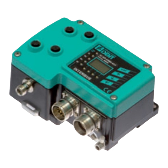
IC-KP-B5-V23 Product Description Displays and controls The following displays and controls are located on the control interface. PWR/ Control IC-KP-B5-V23 NTER LED indicators PWR/ERR Power on green Hardware error 1, 2, 3, 4 Status display for R/W heads green Command on R/W head is active yellow Command executed successfully (approx. -
Page 12: Interfaces And Connections
IC-KP-B5-V23 Product Description Interfaces and connections The following interfaces and connections are located on the control interface IC- KP-B5-V23. Connections M12 connector for R/W heads (sockets) - V1 9-pin M23 round plug connector, outgoing bus interface - M23 9-pin M23 round plug connector, incoming bus interface - M23 M12 connector for power supply (plug) - V1 Other accessories Screw for ground... -
Page 13: Connection Accessories
IC-KP-B5-V23 Product Description Connection accessories 4.7.1 Connection cable for R/W heads and trigger sensors Compatible connection cables with shielding are available for connecting the R/W heads and trigger sensors. Figure 4.2 Accessories Description 2 m long (straight female, angled male) V1-G-2M-PUR-ABG-V1-W 5 m long (straight female, angled male) V1-G-5M-PUR-ABG-V1-W... -
Page 14: Installation
Quick start guide Retain the original packaging in case you have to store or ship the device again at a later date. Should you have any questions, please contact Pepperl+Fuchs. EMC concept The outstanding noise immunity of the IDENTControl against emission and immission is based on its consistent shielding design, which uses the principle of the Faraday cage. -
Page 15: Device Connection
IC-KP-B5-V23 Installation Note! If cables with double shields are used, e.g. wire mesh and metalized foil, the both shields must be connected together, with low resistance, at the ends when making up the cable. Power supply cables are the source of much interference, e.g. from the supply lines of 3-phase electric motors. -
Page 16: Cable Length Between Control Interface And R/W Heads
IC-KP-B5-V23 Installation trigger switch signal Compatible R/W heads see chapter 4.3.1 and compatible connecting cables see chapter 4.7.1. 5.4.3 Cable length between control interface and R/W heads The maximum cable length between the control interface and a connected R/W head is 1000 meters. If you wish to attain the maximum possible cable length, select a suitably large cable cross-section. -
Page 17: Interbus Connection Guide
IC-KP-B5-V23 Installation 5.4.5 INTERBUS connection guide Round connector: Connector - incoming interface /DO1 /DI1 Round connector: Socket - outgoing interface /DO2 /DI2 /RBST... -
Page 18: Cables
IC-KP-B5-V23 Installation 5.4.6 Cables The following INTERBUS remote bus cables should be used: Suitable for laying Parameter Standard Highly flexible underground Cable construction Twisted pairs/i.e. 2-core, common screening Conductor cross- 3 x 2 x 0.22 mm 3 x 2 x 0.25 mm 3 x 2 x 0.22 mm section Operating capacity... -
Page 19: Commissioning
IC-KP-B5-V23 Commissioning Commissioning Connection Warning! Before commissioning, check once again that the connections are correct. Before commissioning, familiarize yourself with the system of communication between your interface module and the read/write station (see chapter 7). Commissioning requires accurate knowledge of INTERBUS and the programming of your master device. -
Page 20: Device Settings
IC-KP-B5-V23 Commissioning Note! The "CMD" manufacturer-independent program is available for planning, commissioning and diagnosing INTERBUS networks. Details of this program and information on the general theme of INTERBUS are available from: INTERBUS-S-Club Postfach 1108 D-32817 Blomberg, Germany http://www.interbusclub.com/de Tel. +49 52 35 / 34 21 00 Fax +49 52 35 / 34 12 34 Device settings Caution! -
Page 21: Operating The Device
IC-KP-B5-V23 Commissioning Configure the read/write station with the described system commands (see chapter 7.4). “99” is preset as the tag type. 6.3.1 Operating the device The following illustration shows how the device is operated directly: Version IDENT- Config Show Config MultiplexM. -
Page 22: Setting The Transfer Rate
IC-KP-B5-V23 Commissioning The view on the display can be toggled by pressing the arrow buttons. The following display variants are available: HEX (hexadecimal with decimal delimiter) HEX2 (hexadecimal without decimal delimiter) ASCII (ASC) Note! Data carrier content from commands that are activated manually on the IDENTControl are always displayed, irrespective of the menu level that was just displayed. -
Page 23: Commands
7.1.1 Outline of the commands and data on the INTERBUS The IDENTControl IC-KP-B5-V23 assigns 5 words to each set of 16 bits (10 bytes) in the framework protocol of the INTERBUS in both communication directions. It is restricted in this to the cyclic transfer of the process data channel. This... - Page 24 IC-KP-B5-V23 Commands Input data field (response): Byte 0 Command code (Echo) Byte 1 Parameter/Toggle flag Byte 2 Status Byte 3 Reply counter Byte 4 Read data Byte N (N is defined by module selection) Read data In order to send a new command to the device, the INTERBUS master must write a command in the output data field.
-
Page 25: Command Types
IC-KP-B5-V23 Commands Enhancedcommands are executed repeatedly as long as the commands remain in the output data field. Execution stops only when a new command for the channel on which the Enhancedcommand was executed is written to the output data field. When the system is switched on, the value on the reply counter is 00h. - Page 26 IC-KP-B5-V23 Commands Standard read/write commands Fixcode Abbre- Command code Command description viation See "single read fixcode (SF)" on page 39 See "Enhanced buffered fixcode (EF)" on page 40 Read data Abbre- Command code Command description viation See "single read words (SR)" on page 41 See "enhanced buffered read words (ER)"...
- Page 27 IC-KP-B5-V23 Commands Writing fixcode IPC11 and IDC-...-1K Abbre- Command code Command description viation See "Single write fixcode (SX)" on page 56 See "Enhanced buffered write fixcode (EX)" on page 58 188d See "Set tag ID code (TI)" on page 60 170d See "Fill data carrier (S#)"...
-
Page 28: System Commands
IC-KP-B5-V23 Commands System commands Change tag (CT) Command: Byte Content Bit no. Byte 0 Command code (04h) Byte 1 Reserved/Ident channel/Toggle bit <Channel> <T> Byte 2 Data carrier type in ASCII <TagType> (high byte) Byte 3 Data carrier type in ASCII <TagType>... - Page 29 IC-KP-B5-V23 Commands Tag type Chip type Access Writable Read only Frequency designation memory code length range High [bytes] [byte] byte byte IPC12 P+F FRAM R/W fixcode 125 kHz All tags conforming to ISO R/W fixcode 13.56 MHz IQC20 15693 IQC21 I-Code SLI (NXP) R/W fixcode 13.56 MHz...
- Page 30 IC-KP-B5-V23 Commands The memory can be encrypted per sector (1 sector = 4 blocks of 16 bytes). The default key in the transponder and the read head is FF FF FF FF FF FF . The key in the read head ASCII can be read with the command Read param and written with the command Write param (see System commands) .
- Page 31 IC-KP-B5-V23 Commands Quit (QU) Command: Byte Content Bit no. Byte 0 Command code (02h) Byte 1 Reserved/Ident channel/Toggle bit <Channel> <T> Byte 2 not used Byte 3 not used Byte 4 not used Byte 5 not used Byte 6 not used Byte 7 not used Response:...
- Page 32 IC-KP-B5-V23 Commands Version (VE): Byte Contents Bit no. Byte 0 Command code Byte 1 Reserved/Toggle bit <T> Byte 2 Parameter <Parameter> Byte 3 Not relevant Byte 9 Not relevant Response: Byte Contents Bit no. Byte 0 Command code Byte 1 Reserved/Toggle bit <T>...
- Page 33 IC-KP-B5-V23 Commands <Parameter> Meaning <Version data> Example Head 2 - type __no__ Head 2 - part number head 2 Head 2 - software number 000000 Head 2 - software date 000000 Head 3 - type IPH-L2 Head 3 - part number 119321 Head 3 - software number 30420_...
- Page 34 IC-KP-B5-V23 Commands Configuration store (CS) Command: Byte Contents Bit no. Byte 2 Command code (17h) Byte 3 Reserved/Ident channel/Toggle bit <Channel> <T> Byte 4 Mode <Mode> Byte 5 not used Byte 6 not used Byte 7 not used Byte 8 not used Byte 9 not used...
- Page 35 IC-KP-B5-V23 Commands Reset (RS) Command: Byte Content Bit no. Byte 0 Command code (16h) Byte 1 Reserved/Channel/Toggle bit <T> Byte 2 not used Byte 3 not used Byte 4 not used Byte 5 not used Byte 6 not used Byte 7 not used This command terminates all active commands.
- Page 36 IC-KP-B5-V23 Commands Set multiplexed mode (MM): Byte Content Bit no. Byte 0 Command code (9Bh) Byte 1 Reserved/Toggle bit <T> Byte 2 Multiplex mode <F> Byte 3 unused Byte 4 unused Byte 5 unused Byte 6 unused Byte 7 unused Response: Byte Content...
- Page 37 IC-KP-B5-V23 Commands Set trigger mode (TM): Byte Contents Bit no. Byte 0 Command code (9Ch) Byte 1 Ident channel/sensor channel/toggle bit <Ident channel> <Sensor channel> <T> Byte 2 Trigger mode <Trigger mode> Byte 3 not used Byte 4 not used Byte 5 not used Byte 6...
- Page 38 IC-KP-B5-V23 Commands If a read/write command is sent to the triggered channel <Ident channel> when trigger mode is active, this command is always activated if the <Sensor channel> transmits status 0. <Ident channel> transmits status 0 to confirm receipt of this command.
-
Page 39: See "Single Read Fixcode (Sf)
IC-KP-B5-V23 Commands Standard read/write commands single read fixcode (SF) Command: Byte Content Bit no. Byte 0 Command code (01h) Byte 1 Reserved/Ident channel/Toggle bit <Channel> <T> Response: Byte Content Bit no. Byte 0 Command code (01h) Byte 1 Reserved/Channel/Toggle bit <Channel>... -
Page 40: 29D 1Dh See "Enhanced Buffered Fixcode (Ef)
IC-KP-B5-V23 Commands Enhanced buffered fixcode (EF) Command: Byte Content Bit no. Byte 0 Command code (1Dh) Byte 1 Reserved/Ident channel/Toggle bit <Channel> <T> Byte 2 not used Byte 3 not used Byte 4 not used Byte 5 not used Byte 6 not used Byte 7 not used... -
Page 41: See "Single Read Words (Sr)
IC-KP-B5-V23 Commands single read words (SR) Command: Byte Content Bit no. Byte 0 Command code (10h) Byte 1 Word number/Ident channel/Toggle bit <WordNum> <Channel> <T> Byte 2 Word address <WordAddr> (high byte) Byte 3 Word address <WordAddr> (low byte) Byte 4 unused Byte 5 unused... -
Page 42: See "Enhanced Buffered Read Words (Er)
IC-KP-B5-V23 Commands enhanced buffered read words (ER) Command: Byte Content Bit no. Byte 0 Command code (19h) Byte 1 Word number/Ident channel/Toggle bit <WordNum> <Channel> <T> Byte 2 Word address <WordAddr> (high byte) Byte 3 Word address <WordAddr> (low byte) Byte 4 unused Byte 5... -
Page 43: See "Single Write Words (Sw)
IC-KP-B5-V23 Commands single write words (SW) Command: Byte Content Bit no. Byte 0 Command code (40h) Byte 1 Word number/Ident channel/Toggle bit <WordNum> <Channel> <T> Byte 2 Word address <WordAddr> (high byte) Byte 3 Word address <WordAddr> (low byte) Byte 4 Data 00h ... -
Page 44: 26D 1Ah See "Enhanced Buffered Write Words (Ew)
IC-KP-B5-V23 Commands enhanced buffered write words (EW) Command: Byte Content Bit no. Byte 0 Command code (1Ah) Byte 1 Word number/Ident channel/Toggle bit <WordNum> <Channel> <T> Byte 2 Word address <WordAddr> (high byte) Byte 3 Word address <WordAddr> (low byte) Byte 4 Data 00h ... -
Page 45: Special Commands
IC-KP-B5-V23 Commands Special commands Note! You can only use the commands in this section for the data carrier type '03' (IPC03). IPC03 Configuration The storage of a data carrier IPC03 is organized by word. A data word is defined with a length of 32 bits. For the normal data range, 29 words from addresses 3 through 31 (<WordAddr>... -
Page 46: Changing The Password
IC-KP-B5-V23 Commands Control word Meaning Byte 0 ... 7 Read range start 8 ... 15 Read range end Password mode on/off "Read after write" operating mode on/off 18 ... 23 Open 24 ... 31 Open IPC03 password mode If the password mode in the data carrier is activated, the data range of the data carrier is read and write-protected and can only be read or written if the R/W head sends the correct password to the data carrier. -
Page 47: See "Set Password Mode (Pm)
IC-KP-B5-V23 Commands Set password mode (PM) Command: Byte Content Bit no. Byte 0 Command code (18h) Byte 1 Reserved/Ident channel/Toggle bit <Channel> <T> Byte 2 Password mode <P> Byte 3 not used Byte 4 not used Byte 5 not used Byte 6 not used Byte 7... -
Page 48: See "Change Password (Pc)
IC-KP-B5-V23 Commands Change password (PC) Command: Byte Content Bit no. Byte 0 Command code (41h) Byte 1 Reserved/Ident channel/Toggle bit <Channel> <T> Byte 2 Old password 00h ... FFh <PSW> (byte 3) Byte 3 Old password 00h ... FFh <PSW> (byte 2) Byte 4 Old password 00h ... -
Page 49: See "Set Password (Ps)
IC-KP-B5-V23 Commands Set password (PS) Command: Byte Content Bit no. Byte 0 Command code (42h) Byte 1 Reserved/Ident channel/Toggle bit <Channel> <T> Byte 2 Reserved Byte 3 Reserved Byte 4 Password 00h ... FFh <PSW> (byte 3) Byte 5 Password 00h ... FFh <PSW>... - Page 50 IC-KP-B5-V23 Commands The advantage of "default read" operating mode is the readout speed. The readout of one data word (4 bytes) is twice as fast in this mode as the other modes. The readout of two words takes approx. 1/3 less time. No more time advantages can be gained after three data words because "default read"...
-
Page 51: See "Single Get Configuration (Sg)
IC-KP-B5-V23 Commands IPC03 configuration Single get configuration (SG) Command: Byte Content Bit no. Byte 0 Command code (61h) Byte 1 Reserved/Ident channel/Toggle bit <Channel> <T> Byte 2 Reserved Byte 3 Address in the configuration range <ConfAddr> Byte 4 not used Byte 5 not used Byte 6... -
Page 52: See "Enhanced Buffered Get Configuration (Eg)
IC-KP-B5-V23 Commands Enhanced buffered get configuration (EG) Command: Byte Content Bit no. Byte 0 Command code (68h) Byte 1 Reserved/Ident channel/Toggle bit <Channel> <T> Byte 2 Reserved Byte 3 Address in the configuration range <ConfAddr> Byte 4 not used Byte 5 not used Byte 6 not used... -
Page 53: See "Single Write Configuration (Sc)
IC-KP-B5-V23 Commands Single write configuration (SC) Command: Byte Content Bit no. Byte 0 Command code (12h) Byte 1 Reserved/Ident channel/Toggle bit <Channel> <T> Byte 2 Reserved Byte 3 Address in the configuration range <ConfAddr> Byte 4 Data 00h ... FFh <Data byte 3>... - Page 54 IC-KP-B5-V23 Commands Byte Bit no. Single write configuration Byte 0 Byte 1 <T> Channel (=1) 02h/03h Byte 2 Byte 3 Word address in the configuration range (=control word) Byte 4 Bits 16 to 31 of the control word Byte 5 Byte 6 Address of the last data word to write...
-
Page 55: See "Enhanced Buffered Write Configuration (Ec)
IC-KP-B5-V23 Commands Enhanced buffered write configuration (EC) Command: Byte Content Bit no. Byte 0 Command code (66h) Byte 1 Reserved/Ident channel/Toggle bit <Channel> <T> Byte 2 Reserved Byte 3 Address in the configuration range <ConfAddr> Byte 4 Data 00h ... FFh <Data byte 3>... -
Page 56: 31D 1Fh See "Single Write Fixcode (Sx)
IC-KP-B5-V23 Commands Write read only code IPC11 and IDC-..-1K "Read-after-write" operating mode is not used. Tags IPC11 can be programmed to behave like the IPC02 read only tag. To do this, use the commands SX and EX. The code is read when tag type '02' or '11' is set with the commands SF and EF. - Page 57 IC-KP-B5-V23 Commands IPC11: <FixLen> <FixType> '02' ASCII (30h 32h), the read only code cannot be changed '11' ASCII (31h 31h), the read only code can be overwritten IDC-...-1K: <FixLen> The first 3 bytes are hexadecimal (0h ... Fh), the last 4 bytes are decimal (0d ...
-
Page 58: See "Enhanced Buffered Write Fixcode (Ex)
IC-KP-B5-V23 Commands Enhanced buffered write fixcode (EX) Command: Byte Content Bit no. Byte 0 Command code (24h) Byte 1 FixLen/Ident channel/Toggle bit <FixLen> <Channel> <T> Byte 2 FixType <FixType> (high byte) Byte 3 FixType <FixType> (low byte) Byte 4 Data 00h ... FFh <Data>... - Page 59 IC-KP-B5-V23 Commands Type IDC-...-1K tags can be programmed in such a way that they are compatible with the type ICC-... read only carriers. This programming occupies the first 8 bytes in the tag. The read/write commands can be used to access the remaining memory.
-
Page 60: Bch See "Set Tag Id Code (Ti)
IC-KP-B5-V23 Commands Set tag ID code (TI) Command: Byte Content Bit no. Byte 0 Command code (BCh) Byte 1 ID length/Channel/Toggle bit <ByteNum> <Channel> <T> Byte 2 Data <ID code> Byte 3 Data <ID code> Byte 4 Data <ID code> Byte 5 Data <ID code>... -
Page 61: Aah See "Fill Data Carrier (S#)
IC-KP-B5-V23 Commands Fill data carrier (S#) Command: Byte Content Bit no. Byte 0 Command code (AAh) Byte 1 Reserved/Ident channel/Toggle bit <Reserved> <Channel> <T> Byte 2 Start address <WordAddr> (high byte) Byte 3 Start address <WordAddr> (low byte) Byte 4 Word count <WordNum>... -
Page 62: 10D 0Ah See "Single Read Special Fixcode (Ss)
IC-KP-B5-V23 Commands Single read special fixcode (SS) Command: Byte Content Bit no. Byte 0 Command code (0Ah) Byte 1 FixLen/Ident channel/Toggle bit <FixLen> <Channel> <T> Byte 2 not used Byte 3 not used Byte 4 not used Byte 5 not used Byte 6 not used Byte 7... -
Page 63: See "Enhanced Read Special Fixcode (Es)
IC-KP-B5-V23 Commands Enhanced read special fixcode (ES) Command: Byte Content Bit no. Byte 0 Command code (71h) Byte 1 Word number/Ident channel/Toggle bit <FixLen> <Channel> <T> Byte 2 not used Byte 3 not used Byte 4 not used Byte 5 not used Byte 6 not used... -
Page 64: 13D 0Dh See "Single Program Special Fixcode (Sp)
IC-KP-B5-V23 Commands Single program special fixcode (SP) Command: Byte Content Bit no. Byte 0 Command code (0Dh) Byte 1 Word number/Ident channel/Toggle bit <FixLen> <Channel> <T> Byte 2 Reserved Byte 3 Reserved Byte 4 ID code 00h ... FFh <ID code> Byte 5 ID code 00h ... -
Page 65: See "Enhanced Program Special Fixcode (Ep)
IC-KP-B5-V23 Commands Enhanced program special fixcode (EP) Command: Byte Content Bit no. Byte 0 Command code (75h) Byte 1 FixLen/Ident channel/Toggle bit <FixLen> <Channel> <T> Byte 2 Reserved Byte 3 Reserved Byte 4 ID code 00h ... FFh <ID code> Byte 5 ID code 00h ... -
Page 66: 107D 6Bh See "Initialize Data Carrier (Si)
IC-KP-B5-V23 Commands Note! The <FixLen> of IDC-...-1K read/write tags is always 6 bytes. Initialize data carrier (SI) Command: Byte Content Bit no. Byte 0 Command code (6Bh) Byte 1 Reserved/Ident channel/Toggle bit <Channel> <T> Response: Byte Content Bit no. Byte 0 Command code (6Bh) Byte 1 Reserved/Ident channel/Toggle bit... -
Page 67: Extended Commands For Type Idc
IC-KP-B5-V23 Commands Extended commands for type IQC-... read/write tags. single write words with lock (SL) Command: Byte Content Bit no. Byte 0 Command code (47h) Byte 1 Word number/Ident channel/Toggle bit <WordNum> <Channel> <T> Byte 2 Word address <WordAddr> (high byte) Byte 3 Word address <WordAddr>... -
Page 68: See "Enhanced Write Words With Lock (El)
IC-KP-B5-V23 Commands Enhanced write words with lock (EL) Command: Byte Contents Bit no. Byte 0 Command code (48h) Byte 1 Word number/Ident channel/Toggle bit <WordNum> <Channel> <T> Byte 2 Word address <WordAddr>(high byte) Byte 3 Word address <WordAddr> (low byte) Byte 4 Data 00h ... -
Page 69: Beh See "Read Param (Rp)
IC-KP-B5-V23 Commands The status '05h' is only output when a tag leaves the detection range or is not yet within the detection range. If two tags enter the read range one immediately after the other, the status '05' is not issued between the two readings. Extended commands for IQH2-... -
Page 70: Bfh See "Write Param (Wp)
IC-KP-B5-V23 Commands write param (WP) Command: Byte Contents Bit no. Telegram length, high byte Byte 0 Telegram length, low byte Byte 1 Byte 2 Command code (BFh) Byte 3 Reserved/Ident channel/Toggle bit <Channel> <T> Byte 4 System code <SystemCode> (high byte) Byte 5 System code <SystemCode>... -
Page 71: Legend
IC-KP-B5-V23 Commands IQH2-...: <SystemCode> 'Q2' ASCII (51 <ParamTyp> 'K1' ASCII (4B RP: reads the key (12 characters ASCII from 0 ... F) from the transponder and the read head WP: writes the key (12 characters ASCII from 0 ... F) into the read head Default key = 'FF FF FF FF FF FF' ASCII IUH-...:... -
Page 72: Fault/Status Messages
IC-KP-B5-V23 Commands <Month> : 2 bytes ASCII, hexadecimal encoding, 01 ... 0C (01=January, 0C=December) <P> : 1 bit, password mode, 0 (0b): Mode off, 1 (1b): Mode on <PSW> : 4 bytes HEX, password <ReplyCounter> : 1 byte, increases by 1 after each response and confirmation. The reply counter starts from 0 after the system is switched on. - Page 73 IC-KP-B5-V23 Commands Status Meaning Reserved Reserved Reserved Internal buffer overflow. Reserved Error messages sent by the bus connection Status Meaning Reserved Reserved Incorrect or incomplete command or parameter not in the valid range. TCP/IP: The specified length of the message does not match the actual length.
-
Page 74: Technical Specifications
IC-KP-B5-V23 Technical specifications Technical specifications Dimensions Ground Connector array General data General data Number of R/W heads max. 4 alternatively 2 R/W heads and 2 trigger sensors Display/controls LEDs 1, 2, 3, 4 Status display for R/W heads green: Command to R/W head active yellow: Approx. - Page 75 IC-KP-B5-V23 Technical specifications LC Display Two-line multifunction display with 12 characters per line Configuration of the control interface and display of connected R/W heads as additional pictograms Simple, direct command input and addressing possible Buttons 4 buttons: ESC, up, down and return Electrical data Rated operational 20 ...
-
Page 76: Troubleshooting
IC-KP-B5-V23 Troubleshooting Troubleshooting Fault location Fault source Possible cause Remedy The operating voltage LED Power supply is interrupted. Ensure that the power supply is (PWR/ERR) does not light up. connected to a 24 V DC source. The LED on the M12 plug lights The polarity of the screw Ensure that the connection up red. -
Page 77: Ascii Table
IC-KP-B5-V23 ASCII table ASCII table ASCII ASCII ASCII ASCII Space " & < >... - Page 78 Twinsburg, Ohio 44087 · USA Tel. +1 330 4253555 E-mail: sales@us.pepperl-fuchs.com Asia Pacific Headquarters Pepperl+Fuchs Pte Ltd. Company Registration No. 199003130E Singapore 139942 Tel. +65 67799091 E-mail: sales@sg.pepperl-fuchs.com www.pepperl-fuchs.com Subject to modifications TDOCT1274B_ENG Copyright PEPPERL+FUCHS • Printed in Germany 05/2011...
Need help?
Do you have a question about the IDENTControl IC-KP-B5-V23 and is the answer not in the manual?
Questions and answers