
Subscribe to Our Youtube Channel
Related Manuals for Pepperl+Fuchs IC-KP-B17-AIDA1


Summary of Contents for Pepperl+Fuchs IC-KP-B17-AIDA1
- Page 1 FACTORY AUTOMATION MANUAL IC-KP-B17-AIDA1 IDENTControl interface with Ethernet interface...
- Page 2 IC-KP-B17-AIDA1 With regard to the supply of products, the current issue of the following document is ap- plicable: The General Terms of Delivery for Products and Services of the Electrical Indus- try, published by the Central Association of the Electrical Industry (Zentralverband Elektrotechnik und Elektroindustrie (ZVEI) e.V.) in its most recent version as well as the...
-
Page 3: Table Of Contents
IC-KP-B17-AIDA1 Introduction................. 7 Declaration of conformity ............8 Declaration of Conformity ..............8 Safety ................... 9 Symbols relevant to safety..............9 Intended use..................9 General notes on safety ............... 9 Protection ................... 10 Product Description ..............11 Range of application................11 Device characteristics ............... - Page 4 IC-KP-B17-AIDA1 Device connection................17 5.4.1 Power supply..................17 5.4.2 Read/Write Head and Trigger Sensors ..........17 5.4.3 Cable length between control interface and R/W heads ....17 5.4.4 Ground connection................17 5.4.5 Ethernet connection guide ............... 18 Commissioning................. 20 Preliminary considerations ...............20 Connection..................20...
- Page 5 IC-KP-B17-AIDA1 Communication via Ethernet/IP............40 7.4.1 General information on communication via Ethernet/IP ....40 7.4.2 Performance spectrum..............40 7.4.3 PLC settings for implicit communication........... 40 7.4.4 Data/Command transfer..............40 7.4.5 Mixed mode ..................41 7.4.6 Separated mode ................41 7.4.7 Data length..................
- Page 6 IC-KP-B17-AIDA1 Exchanging identification data ............99 Data logging ..................100 Technical Specifications ............101 Dimensions ..................101 General Data ..................101 10 Troubleshooting..............103 10.1 Fault/Status messages ..............103 10.2 Troubleshooting................104 11 ASCII table................105 12 Appendix A................106 12.1 Example 1..................106 12.2 Example 2..................110 13 Appendix B................
-
Page 7: Introduction
Introduction Introduction Congratulations You have chosen a device manufactured by Pepperl+Fuchs. Pepperl+Fuchs develops, produces and distributes electronic sensors and interface modules for the market of automation technology on a worldwide scale. Before installing this equipment and put into operation, read this manual carefully. This manual containes instructions and notes to help you through the installation and commissioning step by step. -
Page 8: Declaration Of Conformity
All products were developed and manufactured under observance of the applicable European standards and guidelines. Note! A Declaration of Conformity can be requested from the manufacturer. The product manufacturer, Pepperl+Fuchs GmbH, 68307 Mannheim, has a certified quality assurance system that conforms to ISO 9001. ISO9001... -
Page 9: Safety
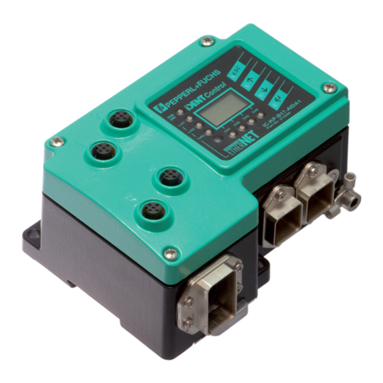
Intended use The IDENTControl IC-KP-B17-AIDA1 is a control interface including an Ethernet interface for identification systems. The device can be used as a control cabinet module or for field applications. Besides the Ethernet connection, you can also connect suitable inductive R/W heads, UHF antennas or trigger sensors. -
Page 10: Protection
IC-KP-B17-AIDA1 Safety Protection In order to improve immunity, enclosures for our components are made from metal, either in part or in whole. read head IDENTControl Figure 3.1 Danger! Electric shock The metallic enclosure components must be connected to protective ground to protect against... -
Page 11: Product Description
IC-KP-B17-AIDA1 Product Description Product Description Range of application The system is suited for the following applications: Automation ■ Material flow control in production ■ Acquisition of operating data ■ Access control ■ Identification of storage vessels, pallets, work piece carriers, refuse containers, tanks, ■... -
Page 12: Handhelds
125 kHz system. IQH-* and IQH1-* read/write heads from Pepperl+Fuchs are compatible with most existing read/write tags that comply with standard ISO 15693. With the IQH2-* read/write heads you can use read/write tags that comply with standard ISO 14443A. -
Page 13: Displays And Controls
IC-KP-B17-AIDA1 Product Description Displays and Controls The following displays and controls are located on the control interface. Control Link1 Link2 Traffic IC-KP-B17-AIDA1 LEDs Description Function Status description Status display for the LED illuminates green as soon as there is an active read/write heads command on the read/write head. -
Page 14: Interfaces And Connections
IC-KP-B17-AIDA1 Product Description Interfaces and connections The control interface IC-KP-B17-AIDA1 has the following interfaces and connections: socket at housing read/write head trigger sensor trigger switch signal voltage supply 1 2 3 4 5 Protection earth Delivery package The delivery package contains: 1 IDENTControl control interface ■... -
Page 15: Power Supply
IC-KP-B17-AIDA1 Product Description 4.7.2 Power Supply The IDENTControl IC-KP-B17-AIDA1 is connected to the power supply via a connector that complies with the AIDA directive. Figure 4.3 Accessories Designation Field attachable connector for power supply ICZ-AIDA1-MSTB MSTB connecting cable to M12 connector ICZ-AIDA1-MSTB-0.2M-PUR-V1-G... -
Page 16: Installation
■ Retain the original packaging in case you have to store or ship the device again at a later date. Should you have any questions, please contact Pepperl+Fuchs. EMC concept The outstanding noise immunity of the IDENTControl against emission and immission is based on its consistent shielding design, which uses the principle of the Faraday cage. -
Page 17: Device Connection
IC-KP-B17-AIDA1 Installation Device connection Electrical connection using plug connectors makes installation simple. 5.4.1 Power supply Connect the power supply for the IDENTControl using a connector that conforms with AIDA. A plug with the following pin assignment is located on the housing:... -
Page 18: Ethernet Connection Guide
IC-KP-B17-AIDA1 Installation Housing Serrated lock washer Crimp connector Lock screw Connecting the IDENTControl to ground Screw the ground conductor to the housing with a crimp connector. 5.4.5 Ethernet connection guide Network connection Connect the network to the IDENTControl using a connector that conforms with AIDA. Two sockets with the following pin assignment are located on the housing: ■... - Page 19 IC-KP-B17-AIDA1 Installation Transfer rates, line lengths and line types The device can be operated in 10 Base-T or 100 Base-TX networks. The maximum total line length is 100 m in both cases and only shielded network cables from category 5 or above can be used.
-
Page 20: Commissioning
IC-KP-B17-AIDA1 Commissioning Commissioning Preliminary considerations Caution! Uncontrolled triggered processes Before commissioning the device, make sure that all processes are running smoothly; otherwise damage may occur in the plant. This manual contains important information required to operate the IDENTControl interface with Ethernet interface. Due to the wide variety of programming options in an Ethernet network, we are unable to include examples relating to commissioning in this manual. -
Page 21: Device Settings
IC-KP-B17-AIDA1 Commissioning Device settings Warning! Device not configured or configured incorrectly Configure the device prior to commissioning. A device that has not been configured or configured incorrectly may lead to faults in the plant. You must set the various parameters prior to commissioning. -
Page 22: Operating The Device
IC-KP-B17-AIDA1 Commissioning Operating the device Version IDENT Setting Show System MultiplexM. information Control IdentControl Status IPH1 IPH2 IPH3 IPH4 IPH1 IPH2 IPH3 IPH4 IPH1 IPH2 IPH3 IPH4 IPH1 IPH2 IPH3 IPH4 IPH1 IPH2 IPH3 IPH4 TagType XX XX XX XX... -
Page 23: Setting The Ip Address
IC-KP-B17-AIDA1 Commissioning Version IDENT Control information IPH1 IPH2 IPH3 IPH4 IPH1 IPH2 IPH3 IPH4 IDENT Setting Setting DHCP Reset? Gateway BUS Address Network DHCP IPH1 IPH2 IPH3 IPH4 IPH1 IPH2 IPH3 IPH4 IPH1 IPH2 IPH3 IPH4 IPH1 IPH2 IPH3 IPH4... -
Page 24: Using The Identification System Without A Dhcp Server
IC-KP-B17-AIDA1 Commissioning If you intend to use a DHCP server, you must select the "Use DHCP" option on the web page. See chapter 8.2 Note! We recommend using a fixed preset IP address in order to avoid system malfunctions. 6.5.1 Using the identification system without a DHCP server The following parameters must be set manually on the web page. -
Page 25: Commands
IC-KP-B17-AIDA1 Commands Commands Data Exchange The transferred data is composed of command, confirmation and response telegrams. Control IDENT Control Command Confirmation (Status FF Response (Execution Status) Response * (Execution Status) * in case of an "enhanced" command The control software (client) sends a command to the IDENTControl (server). The IDENTControl then sends confirmation of receipt (not with MODBUS TCP/IP). -
Page 26: Communication Via Tcp/Ip
7.2.1 General information on data communication via TCP/IP The IC-KP-B17-AIDA1 device was designed to act as a TCP/IP server, which means that the so-called client must send a command to actuate each function. Communication is established via the TCP port 10000. Programming control software requires accurate knowledge of TCP/IP sockets. -
Page 27: Command Examples Tcp / Ip
IC-KP-B17-AIDA1 Commands Response: Byte 0 Telegram length, high byte [(N+1) div 256] Byte 1 Telegram length, low byte [(N+1) mod 256] Byte 2 Command code (echo) Byte 3 Channel / Toggle bit = 0 Byte 4 Status Byte 5 Reply counter... - Page 28 IC-KP-B17-AIDA1 Commands Alternative response: There is no head on channel 1. 00:06:04:02:06:02 00:06 Telegram length (6 bytes) Repeat command code (CT) Reserved / Channel (l), toggle bit (0) Status 6 (hardware error) Reply counter Example 2: Read tag using the single read command For this command example, it is assumed that the tag type IPC03 is set.
-
Page 29: Communication Via Modbus Tcp/Ip
IC-KP-B17-AIDA1 Commands Communication via MODBUS TCP/IP 7.3.1 General Information on Data Communication via MODBUS/TCP Data is exchanged between a MODBUS master (controller) and a MODBUS slave (identification system) by reading and writing registers. The slave contains read and write registers. Data exchange is always initiated by the master. The master initiates an identification system function by transferring an identification command to the write register. - Page 30 IC-KP-B17-AIDA1 Commands Division of the register The device contains four ident channels and a configuration channel. Each channel is assigned a separate register area so that a single master addresses all channels or a separate master addresses each individual channel.
- Page 31 IC-KP-B17-AIDA1 Commands Application example Example 1: Group 1 Group 2 Group 3 Channel 0 (IDENTControl) Channel 1 1000 1000 1000 1122 1124 1124 Channel 2 2000 2000 2000 2122 2124 2124 Channel 3 3000 3000 3000 3122 3124 3124 Channel 4...
- Page 32 IC-KP-B17-AIDA1 Commands Example 2: Group 1 Group 2 Group 3 Logging Controlling Master 0 Master 0 Channel 0 (IDENT Control) Logging Controlling Master 1 Master 1 Channel 1 1000 1000 1000 1122 1124 1124 Logging Controlling Master 2 Master 2...
-
Page 33: Supported Modbus Commands
IC-KP-B17-AIDA1 Commands Groups 2 and 3: FIFO input register and FIFO monitor input register Each area of these groups is divided as follows: Address Byte number of the (0-based, identification telegram decimal) 0 + K Reserved Utilization A 1 + K... - Page 34 IC-KP-B17-AIDA1 Commands 1. A request is issued. The following parameters must be known here: Start address (depending on channel) Channel 0 Channel 1 1000d Channel 2 2000d Channel 3 3000d Channel 4 4000d Number of registers to be written: Maximum 123d Table 7.5...
- Page 35 IC-KP-B17-AIDA1 Commands Second step The identification command change tag must be sent to the identification system to set the tag type. Address Register division Contents Meaning (0-based) Byte number of the identification telegram 2000d High byte Reserved Low byte Reserved/Deletion bit...
- Page 36 IC-KP-B17-AIDA1 Commands Note! When all 3 steps have been completed successfully, LED 2 under the display must light up green. If you then hold a type IPC03 data carrier in front of the reading head, the LED should light up orange. If you wish to transfer an identification command to the identification system a second time, the toggle bit must be inverted to enable the transfer of cyclic data to a PLC.
- Page 37 IC-KP-B17-AIDA1 Commands Address Register division Contents Meaning (0-based) Byte number of the identification telegram 2000d High byte Reserved Low byte Utilization register 6 % of the FIFO memory is utilized 2001d High byte Length of the Byte 0 identification telegram from this byte...
- Page 38 IC-KP-B17-AIDA1 Commands Address Register division Contents Meaning (0-based) Byte number of the identification telegram 2002d High byte Command code enhanced read Byte 2 command Low byte Word number/Channel/ Word count = 0. Byte 3 Toggle bit 4 corresponds to channel 2. Channel number shifted 1 bit to the left.
-
Page 39: General Notes On Creating The Control Program
IC-KP-B17-AIDA1 Commands Reading: Start address Writing start address Number of registers to be read: Maximum 125d Table 7.14 Parameters required for a request 2. The identification system sends a response to the MODBUS master. If an error occurs, the response contains an exception code. -
Page 40: Modbus Exception Codes
IC-KP-B17-AIDA1 Commands 7.3.5 MODBUS exception codes The device issues a response for each MODBUS transaction. The following table contains a list of possible exception codes: Code Name Description Illegal function The function code is not: 03h, 16h, 17h. Illegal data address The registers to be written or read are outside of the defined range. -
Page 41: Mixed Mode
IC-KP-B17-AIDA1 Commands 7.4.5 Mixed mode Channel 1 Channel 2 Output command object Input command object Class 65 Class 64 Channel 3 Instance 06 Instance 06 Attributes 1-4 Attributes 1-4 Channel 4 Channel IDENTControl The five identification channels (four R/W heads, one configuration channel) are addressed using an input and an output instance, with the advantage that the controller requires less memory. -
Page 42: Data Length
IC-KP-B17-AIDA1 Commands 7.4.7 Data length Depending on the data length required, four different attributes with different lengths are available for each input/output instance. Attribute ID Data length Maximum number of double words (4 bytes) that can be read/written at any one time Table 7.17... -
Page 43: Access Administration
IC-KP-B17-AIDA1 Commands Output Input Channel size Required/ instance instance Generated size Output/Input (conf.) byte Sepa- 104d 154d 32 / 32 rated 105d 155d 48 / 48 mode 106d 156d 128 / 128 107d 157d 240 / 240 108d 158d 40 / 40... -
Page 44: Heartbeat And Ident Status
IC-KP-B17-AIDA1 Commands 7.4.10 Heartbeat and ident status If instance 112d and 162d of the assembly object are selected, the size of the output field is 0 bytes and the size of the input that contains the status and reply counter is 10 bytes. - Page 45 IC-KP-B17-AIDA1 Commands Example: Assembly instance 104, single read command Configure output instance 104d first via the display. N14:0 <WordNum> <T> <command> N14:1 <WordAddr> (low byte) <WordAddr>(high byte) N14:2 Write data DW 1 (if not used, please set to 0) N14:3...
-
Page 46: Communication Via Profinet
IC-KP-B17-AIDA1 Commands Some restrictions apply to assembly instances 107d/157d and 111d/161d: The control interface does not support fragmentation protocols. It is, therefore, not possible to send or receive more than 114 words simultaneously. The whole data set must be divided into two separate PCC commands because instances 107d/157d and 111d/161d use more than 114 registers. -
Page 47: Overview Of Characteristics Of The Integrated Profinet Io Device
7.5.2 Overview of the characteristics of the integrated PROFINET IO device In the network, the IDENTControl IC-KP-B17-AIDA1 is a PROFINET IO device that communicates cyclically with the assigned PROFINET IO controller during operation. The IDENTControl IC-KP-B17-AIDA1 supports the range of functions as per Conformance Class B 7.5.3... -
Page 48: Gsdml File And Example Project In The Internet
IC-KP-B17-AIDA1 Commands The "Data Hold Time" is the time after which the identification system may overwrite the input data field. A time longer than the cycle time of the controller attached to the IO controller should be selected. If two data carriers are read directly after one other, the code of the one read first remains in the input data field for the specified time before the next one is entered. -
Page 49: Topology Detection
IC-KP-B17-AIDA1 Commands Figure 7.1 7.5.7 Topology detection To avoid extra effort during commissioning and diagnosis, PROFINET defines a process for topology detection, which displays the system topology graphically in the higher-level controller. The data for representing the topology is stored in the Physical Device (PDEV) of the IDENTControl device. - Page 50 IC-KP-B17-AIDA1 Commands Figure 7.2 HW Konfig / Siemens Step7 Opening the topology editor: 1. Open the topology editor by right-clicking the Ethernet connection and then clicking the "PROFINET IO Topology …" menu item.
- Page 51 IC-KP-B17-AIDA1 Commands Figure 7.3 Opening the topology editor 2. The topology editor opens.
- Page 52 IC-KP-B17-AIDA1 Commands Figure 7.4 Table view The interconnection table lists 3 devices. 3. Open the offline/online comparison by clicking the Offline/online comparison tab. Figure 7.5 Offline/online comparison...
- Page 53 IC-KP-B17-AIDA1 Commands The configured topology (offline) is shown in the left-hand window. The configured topology shows the topology stored in the higher-level controller. 4. Press the "Start" button above the right-hand window to identify the actual topology. The detected topology (online) is shown in the right-hand window.
-
Page 54: Identification & Maintenance Data
IC-KP-B17-AIDA1 Commands Figure 7.7 Graphic view The port interconnections for the connected devices are graphically represented. 7. Confirm the configuration by clicking the "OK" button. The configuration is stored in the higher-level controller as a configured topology. Replacing devices without a removable medium Once the topology has been stored in the controller, each device within the topology can be replaced with another device that is identical in construction. -
Page 55: Command Execution
IC-KP-B17-AIDA1 Commands I&M Data I&M data 1 = system ID location ID I&M data 2 = installation date I&M data 3 = additional information Figure 7.8 Command execution The controller initiates an identification command. The control interface executes the new command if the data has changed since the last read-out. - Page 56 IC-KP-B17-AIDA1 Commands Command: Byte 0* Telegram length, high byte Byte 1* Telegram length, low byte Byte 2 Command code Byte 3 Channel / Toggle bit = 0 Byte 4 Parameter Byte 5 Parameter Byte 6 Data to be written Byte N Data to be written * This byte is only used with the TCP/IP and MODBUS TCP/IP protocol.
-
Page 57: Command Types
IC-KP-B17-AIDA1 Commands Command types When using commands, a distinction is always made between the two command types single mode and enhanced mode. Single mode The command is executed once. A response is issued immediately. Enhanced mode The command remains permanently active until it is interrupted by the user or by an error message. - Page 58 IC-KP-B17-AIDA1 Commands Special command modes Password mode with IPC03 Abbre- Command code Command description viation See "set password mode (PM)" on page 74 See "change password (PC)" on page 75 See "set password (PS)" on page 76 IPC03 configuration Abbre-...
-
Page 59: System Commands
IC-KP-B17-AIDA1 Commands Extended commands for IQH2-... and IUH-... read/write heads With the commands WriteParam WP and ReadParam RD you can configure the IUH-F117- V1 read/write head using different parameters. The parameters are described in the manual for the read/write head. - Page 60 IC-KP-B17-AIDA1 Commands Supported Tag Types Tag type Chip type Access Writable Read only Frequency designation memory code length range High [bytes] [byte] byte byte IPC02 Unique, EM4102 Read only code 125 kHz (EM microelectronic) IPC03 EM4450 (EM Read/write 125 kHz...
- Page 61 The tag type configured in the read/write head as the default is selected. Read/write tags can have 4-byte (older versions) or 7-byte UIDs. IQC42 and IQC43 type read/write tags from Pepperl+Fuchs generally have 7-byte UIDs. Note! In a plant where only one tag type is used, it is advantageous to permanently configure that tag type so that the read/write head detects the tag quicker.
- Page 62 IC-KP-B17-AIDA1 Commands quit (QU) Command: Byte Contents Bit no. Telegram length, high byte Byte 0 Telegram length, low byte Byte 1 Byte 2 Command code (02h) Byte 3 Reserved/Channel/Toggle bit <Channel> <T> This byte is only used with the TCP/IP and MODBUS TCP/IP protocol.
- Page 63 IC-KP-B17-AIDA1 Commands configuration store (CS) Command: Byte Contents Bit no. Telegram length, high byte Byte 0 Telegram length, low byte Byte 1 Byte 2 Command code (17h) Byte 3 Reserved/Ident channel/Toggle <Channel> <T> Byte 4 Mode <M> This byte is only used with the TCP/IP and MODBUS TCP/IP protocol.
- Page 64 IC-KP-B17-AIDA1 Commands reset (RS) Command: Byte Contents Bit no. Telegram length, high byte Byte 0 Telegram length, low byte Byte 1 Byte 2 Command code (16h) Byte 3 Reserved/Channel/Toggle bit <T> This byte is only used with the TCP/IP and MODBUS TCP/IP protocol.
- Page 65 IC-KP-B17-AIDA1 Commands Each IDENT channel sends a response in reply to an MM command. Multiplex mode <F>='0': Mode off <F>='1': Mode on If a R/W head is not connected to a channel, the response telegram receives the status "06h" (hardware fault) from this channel.
-
Page 66: Standard Read/Write Commands
IC-KP-B17-AIDA1 Commands If a trigger command has assigned channel '0' (000b) for <Identchannel>, this change in the status of the trigger sensor (status 0x00 and 0x05) is transmitted to the controller via the sensor channel This function can be used to monitor functions via the controller if trigger signals and reading of data cannot occur simultaneously for application related reasons. - Page 67 IC-KP-B17-AIDA1 Commands enhanced buffered fixcode (EF) Command: Byte Contents Bit no. Telegram length, high byte Byte 0 Telegram length, low byte Byte 1 Byte 2 Command code (1Dh) Byte 3 Reserved/Channel/Toggle bit <Channel> <T> This byte is only used with the TCP/IP and MODBUS TCP/IP protocol.
- Page 68 IC-KP-B17-AIDA1 Commands single read words (SR) Command: Byte Contents Bit no. Telegram length, high byte Byte 0 Telegram length, low byte Byte 1 Byte 2 Command code (10h) Byte 3 Word number/Channel/Toggle bit <WordNum> <Channel> <T> Byte 4 Word address <WordAddr>...
- Page 69 IC-KP-B17-AIDA1 Commands enhanced buffered read words (ER) Command: Byte Contents Bit no. Telegram length, high byte Byte 0 Telegram length, low byte Byte 1 Byte 2 Command code (19h) Byte 3 Word number/Channel/Toggle bit <WordNum> <Channel> <T> Byte 4 Word address <WordAddr>...
- Page 70 IC-KP-B17-AIDA1 Commands single write words (SW) Command: Byte Contents Bit no. Telegram length, high byte <TelegramLenH> Byte 0 Telegram length, low byte <TelegramLenL> Byte 1 Byte 2 Command code (40h) Byte 3 Word number/Channel/Toggle bit <WordNum> <Channel> <T> Byte 4 Word address <WordAddr>...
- Page 71 IC-KP-B17-AIDA1 Commands enhanced buffered write words (EW) Command: Byte Contents Bit no. Telegram length, high byte <TelegramLenH> Byte 0 Telegram length, low byte <TelegramLenL> Byte 1 Byte 2 Command code (1Ah) Byte 3 Word number/Channel/Toggle bit <WordNum> <Channel> <T> Byte 4 Word address <WordAddr>...
-
Page 72: Special Command Modes
IC-KP-B17-AIDA1 Commands 7.8.3 Special Command Modes Note! You can only use the commands in this section for the data carrier type '03' (IPC03). IPC03 Configuration The storage of a data carrier IPC03 is organized by word. A data word is defined with a length of 32 bits. - Page 73 IC-KP-B17-AIDA1 Commands IPC03 password mode If the password mode in the data carrier is activated, the data range of the data carrier is read and write-protected and can only be read or written if the R/W head sends the correct password to the data carrier.
- Page 74 IC-KP-B17-AIDA1 Commands set password mode (PM) Command: Byte Contents Bit no. Telegram length, high byte Byte 0 Telegram length, low byte Byte 1 Byte 2 Command code (18h) Byte 3 Reserved/Channel/Toggle bit <Channel> <T> Byte 4 Password mode <P> This byte is only used with the TCP/IP and MODBUS TCP/IP protocol.
- Page 75 IC-KP-B17-AIDA1 Commands change password (PC) Command: Byte Contents Bit no. Telegram length, high byte Byte 0 Telegram length, low byte Byte 1 Byte 2 Command code (41h) Byte 3 Reserved/Channel/Toggle bit <Channel> <T> Byte 4 Old password 00h ... FFh <PSW>...
- Page 76 IC-KP-B17-AIDA1 Commands set password (PS) Command: Byte Contents Bit no. Telegram length, high byte Byte 0 Telegram length, low byte Byte 1 Byte 2 Command code (42h) Byte 3 Reserved/Channel/Toggle bit <Channel> <T> Byte 4 Reserved Byte 5 Reserved Byte 6 Password 00h ...
- Page 77 IC-KP-B17-AIDA1 Commands Setting "Default Read" 1. Activate the password mode. 2. Write the read range start and end into the "Control Word". 3. Deactivate the password mode. 4. Read the data range with address designation 0000h and word count 0h.
- Page 78 IC-KP-B17-AIDA1 Commands enhanced buffered get configuration (EG): Command: Byte Contents Bit no. Telegram length, high byte Byte 0 Telegram length, low byte Byte 1 Byte 2 Command code (68h) Byte 3 Reserved/Channel/Toggle bit <Channel> <T> Byte 4 Reserved Byte 5 Address in the configuration <ConfAddr>...
- Page 79 IC-KP-B17-AIDA1 Commands single write configuration (SC) Command: Byte Contents Bit no. Telegram length, high byte Byte 0 Telegram length, low byte Byte 1 Byte 2 Command code (12h) Byte 3 Reserved/Channel/Toggle bit <Channel> <T> Byte 4 Reserved Byte 5 Address in the configuration <ConfAddr>...
- Page 80 IC-KP-B17-AIDA1 Commands enhanced buffered write configuration (EC) Command: Byte Contents Bit no. Telegram length, high byte Byte 0 Telegram length, low byte Byte 1 Byte 2 Command code (66h) Byte 3 Reserved/Channel/Toggle bit <Channel> <T> Byte 4 Reserved Byte 5 Address in the configuration <ConfAddr>...
- Page 81 IC-KP-B17-AIDA1 Commands Write read only code IPC11 and IDC-..-1K "Read-after-write" operating mode is not used. Tags IPC11 can be programmed to behave like the IPC02 read only tag. To do this, use the commands SX and EX. The code is read when tag type '02' or '11' is set with the commands SF and EF.
- Page 82 IC-KP-B17-AIDA1 Commands The R/W head makes only one attempt to write a read only code. IPC11: <FixLen> <FixType> '02' ASCII (30h 32h), the read only code cannot be changed '11' ASCII (31h 31h), the read only code can be overwritten IDC-...-1K:...
- Page 83 IC-KP-B17-AIDA1 Commands enhanced buffered write fixcode (EX) Command: Byte Contents Bit no. Telegram length, high byte Byte 0 Telegram length, low byte Byte 1 Byte 2 Command code (24h) Byte 3 FixLen/Channel/Toggle bit <FixLen> <Channel> <T> Byte 4 FixType <FixType> (high byte)
- Page 84 IC-KP-B17-AIDA1 Commands Type IDC-...-1K tags can be programmed in such a way that they are compatible with the type ICC-... read only carriers. This programming occupies the first 8 bytes in the tag. The read/write commands can be used to access the remaining memory.
- Page 85 IC-KP-B17-AIDA1 Commands <ByteNum> = 0h deletes this filter. Note! The TI command only adjusts a setting in the reading head. There is no HF communication with the read/write tags. fill tag (S#) Command: Byte Contents Bit no. Telegram length, high byte...
- Page 86 IC-KP-B17-AIDA1 Commands To write the special read only code use the commands SP and EP; to read it out, use the commands SS and ES. If SP or EP is used to write to an IDC-...-1K tag, the tag is then locked. If you wish to write to the tag again using standard commands, unlock it using the command SI.
- Page 87 IC-KP-B17-AIDA1 Commands enhanced read special fixcode (ES) Command: Byte Contents Bit no. Telegram length, high byte Byte 0 Telegram length, low byte Byte 1 Byte 2 Command code (71h) Byte 3 WordNum/Ident channel/Toggle <FixLen> <Channel> <T> This byte is only used with the TCP/IP and MODBUS TCP/IP protocol.
- Page 88 IC-KP-B17-AIDA1 Commands single program special fixcode (SP) Command: Byte Contents Bit no. Telegram length, high byte Byte 0 Telegram length, low byte Byte 1 Byte 2 Command code (0Dh) Byte 3 Word number/Ident <FixLen> <Channel> <T> channel/Toggle bit Byte 4...
- Page 89 IC-KP-B17-AIDA1 Commands enhanced program special fixcode (EP) Command: Byte Contents Bit no. Telegram length, high byte Byte 0 Telegram length, low byte Byte 1 Byte 2 Command code (75h) Byte 3 FixLen/Ident channel/Toggle bit <FixLen> <Channel> <T> Byte 4 Reserved...
- Page 90 IC-KP-B17-AIDA1 Commands initialize tag (SI) Command: Byte Contents Bit no. Telegram length, high byte Byte 0 Telegram length, low byte Byte 1 Byte 2 Command code (6Bh) Byte 3 Reserved/Channel/Toggle bit <Channel> <T> This byte is only used with the TCP/IP and MODBUS TCP/IP protocol.
- Page 91 IC-KP-B17-AIDA1 Commands Extended commands for type IQC-... read/write tags. single write words with lock (SL) Command: Byte Contents Bit no. Telegram length, high byte Byte 0 Telegram length, low byte Byte 1 Byte 2 Command code (47h) Byte 3 Word number/Ident <WordNum>...
- Page 92 IC-KP-B17-AIDA1 Commands enhanced write words with lock (EL) Command: Byte Contents Bit no. Telegram length, high byte Byte 0 Telegram length, low byte Byte 1 Byte 2 Command code (48h) Byte 3 Word number/Ident <WordNum> <Channel> <T> channel/Toggle bit Byte 4 Word address <WordAddr>...
- Page 93 IC-KP-B17-AIDA1 Commands Extended commands for IQH2-... and IUH-... read/write heads read param (RP) Command: Byte Contents Bit no. Telegram length, high byte Byte 0 Telegram length, low byte Byte 1 Byte 2 Command code (BEh) Byte 3 Reserved/Ident channel/Toggle <Channel>...
- Page 94 IC-KP-B17-AIDA1 Commands write param (WP) Command: Byte Contents Bit no. Telegram length, high byte Byte 0 Telegram length, low byte Byte 1 Byte 2 Command code (BFh) Byte 3 Reserved/Ident channel/Toggle bit <Channel> <T> Byte 4 Reserved Byte 5 System code <SystemCode>...
-
Page 95: Legend
IC-KP-B17-AIDA1 Commands Note! Toggle bit If you send two commands with the same SystemCode and same ParamTyp in succession on the bus interface, you must change the toggle bit in the second command in order for the node to detect the command. -
Page 96: Web Features
IC-KP-B17-AIDA1 Web features Web features Configuring the identification system via web feature The identification system can also be configured using http. In order to activate the device via the network, the IP address and the subnet mask must be configured via the display as a minimum requirement (if no DHCP is used). -
Page 97: Email Function Settings
IC-KP-B17-AIDA1 Web features Email function settings Note! The email function can only be used if you integrate an SMTP server in your network. The device is capable of sending an email when a certain preset error status is active. The following parameters must be configured here. -
Page 98: Security Settings
IC-KP-B17-AIDA1 Web features Mail address sender Enter an email address associated with the device here. The email server may have to recognize the address, depending on the SMTP server. IP address smtp server IP address of the SMTP server Mail triggered on channel by error codes: Status information is allocated to each response telegram. -
Page 99: Exchanging Identification Data
IC-KP-B17-AIDA1 Web features Use client filter, IP address: When the client filter is active, only the network client specified under IP address can exchange data with the server. Web access is still possible, however. Exchanging identification data For commissioning purposes, you can use this link to activate an applet for executing the... -
Page 100: Data Logging
IC-KP-B17-AIDA1 Web features State: The status of the response telegram appears in this field. Data: The data from the response telegram appear in this field (if available). Log: A list of received response telegrams appears in this field. Data logging You can track commands activated in the IDENTControl Compact in the Data logging window. -
Page 101: Technical Specifications
IC-KP-B17-AIDA1 Technical Specifications Technical Specifications Dimensions Ground Connector array General Data General Data Number of read/write Max. 4 heads alternatively 2 read/write heads and 2 trigger sensors UL file number E87056 Displays/Controls LEDs CH1, CH2, CH3, Status display for read/write heads Green: command to read/write head active Yellow: approx. - Page 102 IC-KP-B17-AIDA1 Technical Specifications Power consumption P 3.5 W without read/write heads Galvanic isolation Basic insulation in accordance with DIN EN 50178, rated insulation voltage 50 V Interface 1 Physical Ethernet Protocol SMTP HTTP TCP/IP (port 10000) MODBUS/TCP EtherNet/IP PROFINET IO...
-
Page 103: Troubleshooting
IC-KP-B17-AIDA1 Troubleshooting Troubleshooting 10.1 Fault/Status messages Status Meaning The command has been executed without error. The command is processing. Error messages which triggered the identification system Status Meaning The battery of the read/write tag is weak. Reserved Reserved Incorrect or incomplete command or parameter not in the valid range. -
Page 104: Troubleshooting
IC-KP-B17-AIDA1 Troubleshooting 10.2 Troubleshooting Source of fault Possible cause Remedy The PWR/ERR LED does Power supply not Ensure the power supply using a not illuminate. guaranteed. 24 V DC source. The device is still booting Wait until the booting process is complete. -
Page 105: Ascii Table
IC-KP-B17-AIDA1 ASCII table ASCII table ASCII ASCII ASCII hex ASCII Space " & < >... -
Page 106: Appendix A
IC-KP-B17-AIDA1 Appendix A Appendix A 12.1 Example 1 The following example uses assembly objects 101d/151d (mixed mode) and results in the following: Setting the data carrier IPC02 on channel 1 and channel 3. ■ Reading the read only code from an IPC02 data carrier. - Page 107 IC-KP-B17-AIDA1 Appendix A A response appears in the input field: Byte no. Contents Description Byte 0 Command code Command CT (Change tag) Byte 1 Number of double words/ Channel = 1 Channel/Toggle bit Toggle bit = 0 Byte 2 Status Command executed.
- Page 108 IC-KP-B17-AIDA1 Appendix A Reading data carriers on the R/W heads on channels 1 and 3. Send a Single readcommand to channel 1 as an implicit command: Byte no. Contents Description Byte 0 Command code Command SF (Single read read only code)
- Page 109 IC-KP-B17-AIDA1 Appendix A Byte no. Contents Description Byte 4 ID code 00h ... FFh <ID code> Byte 5 ID code 00h ... FFh <ID code> Byte 6 ID code 00h ... FFh <ID code> Byte 7 ID code 00h ... FFh <ID code>...
-
Page 110: Example 2
IC-KP-B17-AIDA1 Appendix A A response appears in the input field: Byte no. Contents Description Byte 0 Command code Command SF (Single read read only code) Byte 1 Channel/Toggle bit Channel = 3 Toggle bit = 0 Byte 2 Status Command executed. - Page 111 IC-KP-B17-AIDA1 Appendix A Output instance 104d - 32 bytes Bytes Class, instance, attribute Description 0 - 7 64h, 01d, 01h Channel 1 [8] 8 - 15 64h, 02d, 01h Channel 2 [8] 16 - 23 64h, 03d, 01h Channel 3 [8]...
- Page 112 IC-KP-B17-AIDA1 Appendix A Ele- Implicit Contents Description ment telegram Byte 16 No commands are transmitted to channel 3. Byte 23 Byte 24 No commands are transmitted to channel 4. Byte 31 A command confirmation appears in the input field: Ele-...
- Page 113 IC-KP-B17-AIDA1 Appendix A A response appears in the input field: Ele- Implicit Contents Description ment telegram Byte 0 Command code Command CT (Change tag) Byte 1 Number of double words/ Channel = element = 1 Channel/Toggle bit Toggle bit = 0...
- Page 114 IC-KP-B17-AIDA1 Appendix A Sending a write command as an implicit command Ele- Implicit Contents Description ment telegram Byte 0 Command code Command SW (Single write double words) Byte 1 Number of double words/ 1 double word = 4 bytes Channel/Toggle bit Element defines the channel.
- Page 115 IC-KP-B17-AIDA1 Appendix A A command confirmation appears in the input field: Ele- Implicit Contents Description ment telegram Byte 0 Command code Command SW (Single write double words) Byte 1 Number of double words/ 1 double word = 4 bytes Channel/Toggle bit...
- Page 116 IC-KP-B17-AIDA1 Appendix A A response appears in the input field: Ele- Implicit Contents Description ment telegram Byte 0 Command code Command SW (Single write double words) Byte 1 Number of double words/ Element defines channel. Channel/Toggle bit Toggle bit = 0...
- Page 117 IC-KP-B17-AIDA1 Appendix A Sending a read command as an implicit command Ele- Implicit Contents Description ment telegram Byte 0 Command code Command SR (Single read double words) Byte 1 Number of double words/ 1 double word = 4 bytes Channel/Toggle bit Element defines the channel.
- Page 118 IC-KP-B17-AIDA1 Appendix A A command confirmation appears in the input field: Ele- Implicit Contents Description ment telegram Byte 0 Command code Command SR (Single read words) Byte 1 Number of double words/ 1 double word = 4 bytes Channel/Toggle bit...
- Page 119 IC-KP-B17-AIDA1 Appendix A A response appears in the input field: Ele- Implicit Contents Description ment telegram Byte 0 Command code Command SR (Single read words) Byte 1 Number of double words/ 1 double word = 4 bytes Channel/Toggle bit Channel = element = 1...
-
Page 120: Appendix B
IC-KP-B17-AIDA1 Appendix B Appendix B 13.1 Object model Class Object name Number of instances Identity Assembly Output command for channels 1-4, IDENTControl and mixed mode Input command for channels 1-4, IDENTControl and mixed mode Boot-up parameters Diagnostics 13.1.1 Identity object (01h) -
Page 121: Assembly Object (04H)
IC-KP-B17-AIDA1 Appendix B 13.1.2 Assembly object (04h) These instances are taken from classes 64h and 65h. Class attributes (instance 0) Attribute ID Name Data type Data content Access authorization Revision UINT Max. instance UINT I/O output instance USINT Get / Set... - Page 122 IC-KP-B17-AIDA1 Appendix B Output instance 105d - 48 bytes Bytes Class, instance, attribute Description 0 - 11 64h, 01d, 02h Channel 1 [12] 12 - 23 64h, 02d, 02h Channel 2 [12] 24 - 35 64h, 03d, 02h Channel 3 [12]...
- Page 123 IC-KP-B17-AIDA1 Appendix B Output instance 111d - 248 bytes Bytes Class, instance, attribute Description 0 - 59 64h, 01d, 04h Channel 1 [60] 60 - 119 64h, 02d, 04h Channel 2 [60] 120 - 179 64h, 03d, 04h Channel 3 [60]...
- Page 124 IC-KP-B17-AIDA1 Appendix B Bytes Class, instance, attribute Description 24 - 35 65h, 03d, 02h Channel 3 [12] 36 - 47 65h, 04d, 02h Channel 4 [12] Input instance 156d - 128 bytes Bytes Class, instance, attribute Description 0 - 31...
- Page 125 IC-KP-B17-AIDA1 Appendix B Input instance 161d - 248 bytes Bytes Class, instance, attribute Description 0 - 59 65h, 01d, 04h Channel 1 [60] 60 - 119 65h, 02d, 04h Channel 2 [60] 120 - 179 65h, 03d, 04h Channel 3 [60]...
-
Page 126: Input Command Object (Instances 65H - 6)
IC-KP-B17-AIDA1 Appendix B 13.1.4 Input command object (instances 65h - 6) Class attributes (instance 0) Attribute ID Name Data type Data content Access authorization Revision UINT Explicit status USINT[10] Instance attributes (instances 1-6) Instances 1-4: R/W heads 1-4 ■ Instance 5 - Ident Control ■... -
Page 127: Diagnostics Object (Instances 67H - 5)
IC-KP-B17-AIDA1 Appendix B Shared services Service code integrated in service designation Class level Instance level Get attribute single Get attribute single 13.1.6 Diagnostics object (instances 67h - 5) Class attributes (instance 0) Attribute ID Name Data type Data content Access... - Page 128 Twinsburg, Ohio 44087 · USA Tel. +1 330 4253555 E-mail: sales@us.pepperl-fuchs.com Asia Pacific Headquarters Pepperl+Fuchs Pte Ltd. Company Registration No. 199003130E Singapore 139942 Tel. +65 67799091 E-mail: sales@sg.pepperl-fuchs.com www.pepperl-fuchs.com Subject to modifications / TDOCT-1775F_ENG Copyright PEPPERL+FUCHS • Printed in Germany 02/2014...
Need help?
Do you have a question about the IC-KP-B17-AIDA1 and is the answer not in the manual?
Questions and answers