
Subscribe to Our Youtube Channel
Related Manuals for Pepperl+Fuchs IC-KP-R2-V1


Summary of Contents for Pepperl+Fuchs IC-KP-R2-V1
- Page 1 FACTORY AUTOMATION MANUAL IC-KP-R2-V1 IDENTControl interface with serial interface...
- Page 2 IC-KP-R2-V1 With regard to the supply of products, the current issue of the following document is ap- plicable: The General Terms of Delivery for Products and Services of the Electrical Indus- try, published by the Central Association of the Electrical Industry (Zentralverband Elektrotechnik und Elektroindustrie (ZVEI) e.V.) in its most recent version as well as the...
-
Page 3: Table Of Contents
IC-KP-R2-V1 Introduction................. 5 Declaration of conformity ............6 Declaration of conformity..............6 Safety ................... 7 Symbols relevant to safety..............7 Intended use..................7 General notes on safety ............... 7 Contact protection ................8 Product Description ..............9 Range of application................9 Device characteristics ................. - Page 4 IC-KP-R2-V1 Device connection................15 5.4.1 Power supply..................15 5.4.2 Read/Write Head and Trigger Sensors ..........15 5.4.3 Cable length between control interface and R/W heads ....16 5.4.4 Ground connection................16 5.4.5 Instructions for connecting the command interface ......16 Commissioning................. 18 Commissioning...................18...
-
Page 5: Introduction
Introduction Introduction Congratulations You have chosen a device manufactured by Pepperl+Fuchs. Pepperl+Fuchs develops, produces and distributes electronic sensors and interface modules for the market of automation technology on a worldwide scale. Before installing this equipment and put into operation, read this manual carefully. This manual containes instructions and notes to help you through the installation and commissioning step by step. -
Page 6: Declaration Of Conformity
This product was developed and manufactured under observance of the applicable European standards and guidelines. Note! A Declaration of Conformity can be requested from the manufacturer. The product manufacturer, Pepperl+Fuchs GmbH, D-68307 Mannheim, has a certified quality assurance system that conforms to ISO 9001. ISO9001... -
Page 7: Safety
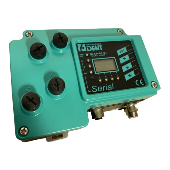
Intended use The IDENTControl IC-KP-R2-V1 is a control interface including a serial interface for identification systems. The device can be used as a control cabinet module or for field applications. Besides the serial connection, suitable inductive R/W heads, microwave antennas or trigger sensors can be connected. -
Page 8: Contact Protection
IC-KP-R2-V1 Safety Contact protection Our housings are manufactured using components made partly or completely from metal to improve noise immunity. Read head IDENTControl Compact Danger! Electric shock The metallic housing components are connected to ground to protect against dangerous voltages that may occur in the event of a fault in the SELV power supply! -
Page 9: Product Description
125 kHz system. IQH-* and IQH1-* read/write heads from Pepperl+Fuchs are compatible with most existing read/write tags that comply with standard ISO 15693. With the IQH2-* read/write heads you can use read/write tags that comply... -
Page 10: Handhelds
IC-KP-R2-V1 Product Description The 13.56 MHz technology even allows smart labels (read/write tags in the form of adhesive labels with printed barcode). Currently available read/write tags have a memory capacity of 64 bits of read only code and a maximum 2 KB of programmable memory. -
Page 11: Interfaces And Connections
Up menu item Down menu item RETURN (confirm input) Interfaces and connections The following interfaces and connections are located on the control interface IC-KP-R2-V1. Connections M12 connector for R/W heads (sockets) - V1 M12 connector for power supply (plug) - V1... -
Page 12: Connection Accessories
IC-KP-R2-V1 Product Description Connection accessories 4.7.1 Connection cable for R/W heads and trigger sensors Compatible connection cables with shielding are available for connecting the R/W heads and trigger sensors. Figure 4.2 Accessories Description 2 m long (straight female, angled male) -
Page 13: Connection Cable To The Serial Interface
IC-KP-R2-V1 Product Description 4.7.3 Connection cable to the serial interface The IDENT Control IC-KP-R2-V1 has an M12 connector and is connected to the host using a suitable cable. Figure 4.4 Accessories Designation M12 cable connector, shielded, field-attachable V1S-G-ABG-PG9 Adapter cable, M12 to Sub-D (for connection to a PC V1S-G-0.15M-PUR-ABG-SUBD... -
Page 14: Installation
■ Retain the original packaging in case you have to store or ship the device again at a later date. Should you have any questions, please contact Pepperl+Fuchs. EMC concept The outstanding noise immunity of the IDENTControl against emission and immission is based on its consistent shielding design, which uses the principle of the Faraday cage. -
Page 15: Device Connection
IC-KP-R2-V1 Installation Device connection Electrical connection using plug connectors makes installation simple. 5.4.1 Power supply Connect the power supply via an M12 connector with integrated voltage and reverse polarity protection indicator (green: correct polarity, red: reverse polarity). A plug with the following pin... -
Page 16: Cable Length Between Control Interface And R/W Heads
IC-KP-R2-V1 Installation 5.4.3 Cable length between control interface and R/W heads The maximum cable length between the control interface and a connected R/W head is 1000 meters. If you wish to attain the maximum possible cable length, select a suitably large cable cross-section. - Page 17 IC-KP-R2-V1 Installation Host-PC IC-KP-R2-V1 Transfer rates, line lengths and line types The maximum length of the cable between the control unit and the higher level computer depends on the transfer rate and the noise level. We recommend the following guide value:...
-
Page 18: Commissioning
IC-KP-R2-V1 Commissioning Commissioning Commissioning 6.1.1 Connection Warning! Before commissioning, check once again that the connections are correct. After the supply voltage is connected, the green LED in the voltage connector and the PWR and UL LEDs on the display panel must light up. If the LED in the connector lights up red, the polarity of the power supply is reversed. -
Page 19: Output Of The Contents Of Read Data Carriers On The Display
IC-KP-R2-V1 Commissioning Operating the device The following illustration shows how the device is operated directly: Versions- IDENT- IdentControl Konfigstatus MultiplexM. information Control... Einstellung IdentControl IPH1 IPH2 IPH3 IPH4 IPH1 IPH2 IPH3 IPH4 IPH1 IPH2 IPH3 IPH4 IPH1 IPH2 IPH3 IPH4... -
Page 20: Operating With The Communication Interface
6.1.4 Operating with the communication interface The procedure for commissioning the IDENTControl IC-KP-R2-V1 using the serial RS 232 interface in conjunction with a PC and an IPC03 data carrier is described in the following section. It is assumed that the IDENTControl is in factory default condition when all of the following steps are performed. - Page 21 IC-KP-R2-V1 Commissioning Example: 00 P+F IDENT<CR><LF> IC-KP-R2-V1<CR><LF> #126457<CR><LF> 1830373 <CR><LF> 01.07.05 #<CR> ... Details of connected R/W heads follow. For the complete response, see see chapter 7.3.1. Note! If you receive different responses, communication between your PC and the device has failed (the software number and the software date may vary).
-
Page 22: Commands
IC-KP-R2-V1 Commands Commands General information on the serial interface The serial RS-232 interface enables the quick and easy connection of an IDENTControl to a PC or PLC. The configuration of device addresses is not required. The configuration is limited setting the required baud rate. Commands can be sent to the IDENTControl using any terminal program. - Page 23 IC-KP-R2-V1 Commands 2. Example: Writing two double words from address 7 with R/W head on channel 1 To write two double words to channel 1 from address 7 with a R/W head, proceed as follows. 1. Position an IPC03 data carrier in front of the R/W head on channel 1.
-
Page 24: Command Types
IC-KP-R2-V1 Commands Command types When using commands, a distinction is always made between the two command types single mode and enhanced mode. Single mode The command is executed once. A response is issued immediately. Enhanced mode The command remains permanently active until it is interrupted by the user or by an error message. - Page 25 IC-KP-R2-V1 Commands Special command modes Password mode with IPC03 Command description Abbreviation See "Set password mode (PM):" on page 34 See "Change password (PC):" on page 34 See "Set password (PS):" on page 35 Configuration IPC03 Command description Abbreviation See "Single get configuration (SG):" on page 35 See "Enhanced buffered get configuration (EG):"...
-
Page 26: System Commands
IC-KP-R2-V1 Commands Note! The device makes no distinction between commands entered in upper and lower case. Make sure that there are no spaces in all parameters that come after the command. 7.3.1 System commands Version (VE): Command: VE <CHCK><ETX> Response: <Status>... - Page 27 IC-KP-R2-V1 Commands Tag type Chip type Access Writable Read only Frequency designation memory code length range High [bytes] [byte] byte byte All ISO 15693 Read/write read 13.56 MHz IQC20 compliant read/write only code tags IQC21 I-Code SLI (NXP) Read/write read 13.56 MHz...
- Page 28 The tag type configured in the read/write head as the default is selected. Read/write tags can have 4-byte (older versions) or 7-byte UIDs. IQC42 and IQC43 type read/write tags from Pepperl+Fuchs generally have 7-byte UIDs. Note! In a plant where only one tag type is used, it is advantageous to permanently configure that tag type so that the read/write head detects the tag quicker.
- Page 29 IC-KP-R2-V1 Commands Configure interface (CI): Command: CI <Timeout>,<Baud><CHCK><ETX> Response: <Status><Ident channel><CHCK><ETX> This command sets the timeout and the baud rate. The values are stored in the non-volatile memory of the control unit. Note! The device settings stored in the non-volatile memory always become active after a reset.
- Page 30 IC-KP-R2-V1 Commands Reset to defaults (RD): Command: RD <CHCK><ETX> Response: 0<Ident channel><CHCK><ETX> This command terminates all active commands. The control unit is reset to the factory settings. Note! The device settings stored in the non-volatile memory always become active after a reset.
-
Page 31: Standard Read/Write Commands
IC-KP-R2-V1 Commands <Ident channel>=0 allows you to assign the trigger signal to channel '0' so that the trigger signal is transmitted to the controller and not to a read head. This function can be used to monitor functions via the PLC if trigger signals and reading of data cannot occur simultaneously for application related reasons. - Page 32 IC-KP-R2-V1 Commands Enhanced buffered write words (EW): Command: EW <Ident channel><WordAddr><WordNum><Data> <CHCK><ETX> Response: <Status><Ident channel><CHCK><ETX> The read/write head repeatedly attempts to write <WordNum> 32-bit words from the address <WordAddr> until successful. After each successful write, the head sends the response and then switches to continuous read.
-
Page 33: Special Command Modes
IC-KP-R2-V1 Commands 7.3.3 Special command modes Note! You can only use the commands in this section for the data carrier type '03' (IPC03). IPC03 Configuration The storage of a data carrier IPC03 is organized by word. A data word is defined with a length of 32 bits. - Page 34 IC-KP-R2-V1 Commands IPC03 password mode If the password mode in the data carrier is activated, the data range of the data carrier is read and write-protected and can only be read or written if the R/W head sends the correct password to the data carrier.
- Page 35 IC-KP-R2-V1 Commands Set password (PS): Command: PS <Ident channel><PW><CHCK><ETX> Response: <Status><Ident channel><CHCK><ETX> The command PSsets the password, which the R/W head communicates to the data carrier in password mode. Operating mode “Default Read” In "default read" operating mode, 1 or 2 words are read extremely quickly. The area of memory earmarked for reading is already specified on the tag.
- Page 36 IC-KP-R2-V1 Commands Single write configuration (SC): Command: SC <Ident channel><ConfAddr><Data><CHCK><ETX> Response: <Status><Ident channel><CHCK><ETX> The R/W head makes exactly one attempt to write a word to the configuration range ("Protection Word" or "Control Word") from the address <ConfAddr>. The password mode must be active so that the R/W head can write to the configuration range.
- Page 37 IC-KP-R2-V1 Commands Write read only code IPC11 and IDC-..-1K "Read-after-write" operating mode is not used. Tags IPC11 can be programmed to behave like the IPC02 read only tag. To do this, use the commands SX and EX. The code is read when tag type '02' or '11' is set with the commands SF and EF.
- Page 38 IC-KP-R2-V1 Commands The R/W head constantly attempts to write a read only code. After each successful write, the response is sent and the system waits until a new tag is within the detection range. The command then starts again from the beginning.
- Page 39 IC-KP-R2-V1 Commands Single read special read only code (SS): Command: SS <Ident channel><FixLen><CHCK><ETX> Response: <Status><Ident channel><ID code><CHCK><ETX> The R/W head makes only one attempt to read a special read only code. Note! The <FixLen> of IDC-...-1K read/write tags is always 6 bytes.
- Page 40 IC-KP-R2-V1 Commands Initialize data carrier (SI): Command: SI <Ident channel><CHCK><ETX> Response: <Status><Ident channel><Data><CHCK><ETX> This command allows conventional reading and writing of IDC-...-1K read/write tags that were configured using the EP or SP commands. Extended commands for type IQC-... read/write tags.
- Page 41 IC-KP-R2-V1 Commands Example: RP1UE5.00.00 outputs the number of unsuccessful read attempts until status 5. Syntax <SystemCode><ParamTyp> Write Parameters Command WP writes configuration parameters to the read/write head. Command: WP <ChanNo> <SystemCode> <ParamTyp> <DataLength> <Data> <CHCK> <ETX> Response: <Status> <ChanNo> <CHCK> <ETX>...
-
Page 42: Legend
: 1 ASCII characters, 10d, line feed <Mode> : 1 ASCII character, '0' Configuration store off '1': Configuration store on <Model type> : Product order code: IC-KP-R2-V1 <Month> : 2 ASCII bytes, hexadecimal encoding, 01 ... 0C (01=January, 0C=December) <NewPW> : 4 bytes HEX, new password <P>... -
Page 43: Fault/Status Messages
IC-KP-R2-V1 Commands <Timeout> : 1 to 3 ASCII characters Timeout of interface in (0 ... 100) x 100 ms, an error message is sent after this time runs out. '0' deactivates the timeout <Trigger mode> : 1 ASCII character '0': Trigger mode off... -
Page 44: Technical Specifications
IC-KP-R2-V1 Technical Specifications Technical Specifications Dimensions Ground Connector array General data General data Number of R/W heads max. 4 alternatively 2 R/W heads and 2 trigger sensors Displays/controls LEDs 1, 2, 3, 4 Status display for R/W heads green: Command to R/W head active yellow: Approx. - Page 45 IC-KP-R2-V1 Technical Specifications Electrical data Rated operational voltage U 20 ... 30 V DC , PELV Ripple 10 % at 30 V DC Current consumption 2 A incl. R/W heads Power consumption P 3.5 W without R/W heads...
-
Page 46: Troubleshooting
IC-KP-R2-V1 Troubleshooting Troubleshooting Fault location Fault source Possible cause Remedy The operating voltage LED Power supply is interrupted. Ensure that the power supply (PWR/ERR) does not light up. is connected to a 24 V DC source. The LED on the M12 plug... -
Page 47: Ascii Table
IC-KP-R2-V1 ASCII table ASCII table ASCII ASCII ASCII hex ASCII Space " & < >... - Page 48 Twinsburg, Ohio 44087 · USA Tel. +1 330 4253555 E-mail: sales@us.pepperl-fuchs.com Asia Pacific Headquarters Pepperl+Fuchs Pte Ltd. Company Registration No. 199003130E Singapore 139942 Tel. +65 67799091 E-mail: sales@sg.pepperl-fuchs.com www.pepperl-fuchs.com Subject to modifications / DOCT-0222E Copyright PEPPERL+FUCHS • Printed in Germany 03/2014...
Need help?
Do you have a question about the IC-KP-R2-V1 and is the answer not in the manual?
Questions and answers