
Related Manuals for Pepperl+Fuchs ICE1 G60L-V1D Series


Summary of Contents for Pepperl+Fuchs ICE1 G60L-V1D Series
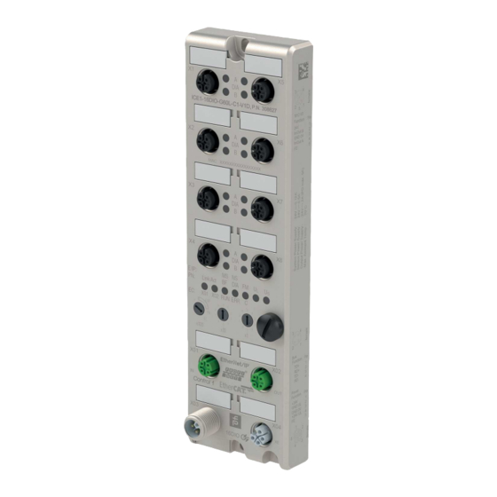
- Page 1 ICE1-*-G60L-V1D, ICE1-*-G60L-C1-V1D Fieldbus Modules with Multiprotocol Technology Manual...
- Page 2 Phone: +49 621 776 - 0 E-mail: info@de.pepperl-fuchs.com North American Headquarters Pepperl+Fuchs Inc. 1600 Enterprise Parkway Twinsburg, Ohio 44087 Phone: +1 330 425-3555 E-mail: sales@us.pepperl-fuchs.com Asia Headquarters Pepperl+Fuchs Pte. Ltd. P+F Building 18 Ayer Rajah Crescent Singapore 139942 Phone: +65 6779-9091 E-mail: sales@sg.pepperl-fuchs.com https://www.pepperl-fuchs.com...
-
Page 3: Table Of Contents
ICE1-*-G60L-V1D, ICE1-*-G60L-C1-V1D Contents Safety .......................... 5 Introduction....................5 1.1.1 Content of this Document ..............5 1.1.2 Manufacturer..................5 1.1.3 Target Group, Personnel ..............5 1.1.4 Symbols Used ................... 6 Product Description ....................7 Use and Application ..................7 Displays and Operating Elements..............9 Interfaces and Connections ............... - Page 4 ICE1-*-G60L-V1D, ICE1-*-G60L-C1-V1D Contents Assigning Process Data ................60 6.3.1 16DIO Modules, Bit Assignment of Process Data ......60 6.3.2 Modules with Decentralized Control Function, Bit Assignment of Pro- cess Data Extension63 6.3.3 16DI Modules, Bit Assignment of Process Data ....... 64 6.3.4 8DI/8DO Modules, Bit Assignment of Process Data......
-
Page 5: Safety
Control drawings • Instruction manual • Other documents 1.1.2 Manufacturer Pepperl+Fuchs Group Lilienthalstraße 200, 68307 Mannheim, Germany Internet: www.pepperl-fuchs.com 1.1.3 Target Group, Personnel Responsibility for planning, assembly, commissioning, operation, maintenance, and dismount- ing lies with the plant operator. Only appropriately trained and qualified personnel may carry out mounting, installation, com- missioning, operation, maintenance, and dismounting of the product. -
Page 6: Symbols Used
ICE1-*-G60L-V1D, ICE1-*-G60L-C1-V1D Safety 1.1.4 Symbols Used This document contains symbols for the identification of warning messages and of informative messages. Warning Messages You will find warning messages, whenever dangers may arise from your actions. It is mandatory that you observe these warning messages for your personal safety and in order to avoid prop- erty damage. -
Page 7: Product Description
ICE1-*-G60L-V1D, ICE1-*-G60L-C1-V1D Product Description Product Description Use and Application Module Description The ICE1-*-G60L-*- modules function as an interface in an industrial fieldbus system. They enable communication between a central controller at the control level and the decentralized sensors and actuators at the field level. To do so, in addition to the fieldbus interface, different variants of the modules have a different number of ports for digital inputs and outputs. - Page 8 ICE1-*-G60L-V1D, ICE1-*-G60L-C1-V1D Product Description Special Product Features • Robust design Connectivity options for the module series include the widespread M12 connector with A encoding for I/O signals and D coding for the network. In addition, the connectors are color-coded to prevent confusion of the ports. The output circuits are galvanically isolated from the rest of the network and the sensor electronics.
-
Page 9: Displays And Operating Elements
ICE1-*-G60L-V1D, ICE1-*-G60L-C1-V1D Product Description • Automatic configuration of inputs/outputs on 16DIO modules via input/output profiles The 16DIO modules can be used universally and offer a variety of input/output profiles as basic configuration. By selecting a predefined profile, you can very easily preconfigure a 16DIO module as, among other things, a 16DI, 16DO, or 8DI8DO module. - Page 10 ICE1-*-G60L-V1D, ICE1-*-G60L-C1-V1D Product Description Displays - General Part Description for LED A, B, DIA, U , DCU/FM Function LED A (for each of X1 White: channel A status is "on” - X8) Off: no error, not connected Red: peripheral error (sensor/actuator overload or short circuit) LED B X1 - X8 B White: channel B status is "on”...
- Page 11 ICE1-*-G60L-V1D, ICE1-*-G60L-C1-V1D Product Description PROFINET Displays P area: relevant LEDs Lnk/Act, BF, DIA Function LED Lnk/Act Green: connection to an Ethernet node Flashing yellow: data exchange with an IO device Off: no connection LED BF Red: no configuration, slow or no physical connection Flashing red: no data exchange with IO device Off: no error LED DIA...
-
Page 12: Interfaces And Connections
ICE1-*-G60L-V1D, ICE1-*-G60L-C1-V1D Product Description Interfaces and Connections The contact arrangements below show the front view of the plug-in area of the connectors. Fieldbus Connection X01, X02 • Connection: M12 socket, 4 pin, D-coded • Color coding: green Figure 2.2 Schematic drawing of port X01, X02 Port Signal Function... - Page 13 ICE1-*-G60L-V1D, ICE1-*-G60L-C1-V1D Product Description Figure 2.4 Schematic drawing of M12 L-encoding (socket); port X04 (OUT) Port Signal Function Power supply (+24 V) Sensor/system supply X03, X04 GND U Ground/reference potential V GND U Ground/reference potential V (+24 V) Auxiliary power supply (galv. insulated) FE (5) FE (FE) Functional ground...
-
Page 14: Dimensions
ICE1-*-G60L-V1D, ICE1-*-G60L-C1-V1D Product Description Port Signal Function Outputs Not used X5 ... X8 OUT B Digital output B 0 VDC Ground/reference potential OUT A Digital output A FE (5) FE (FE) Functional ground Module ICE1-16DI-G60L-V1D Port Signal Function Inputs +24 VDC Sensor/system supply X1 ... -
Page 15: Installation
ICE1-*-G60L-V1D, ICE1-*-G60L-C1-V1D Installation Installation General Information Install the module with two M6x25/30 size screws on a level surface. The required torque is 1 Nm. Use washers according to DIN 125. For the installation holes, use a spacing of 237.3 mm to 239.7 mm. Note Power supply connection When connecting the power supply, ensure a separate power supply to the sensor and system... - Page 16 ICE1-*-G60L-V1D, ICE1-*-G60L-C1-V1D Installation Warning! Use temperature-resistant cable with heat resistance up to at least 96 °C for the following Ethernet IO modules: ICE1-8DI8DO-G60L-C1-V1D and ICE1-8DI8DO-G60L-V1D ICE1-16DIO-G60L-V1D and ICE1-16DIO-G60L-C1-V1D...
-
Page 17: Commissioning, Protocol Setting
ICE1-*-G60L-V1D, ICE1-*-G60L-C1-V1D Commissioning, Protocol Setting Commissioning, Protocol Setting Setting Protocols Multiprotocol You can use the multiprotocol modules to select various protocols for communication within a fieldbus system. This allows you to integrate the multiprotocol modules into different networks without having to obtain a specific module for each protocol. This technology also allows you to use the same module in different environments. - Page 18 When restoring the factory settings, ensure that the module is connected to the power supply and switched on for at least 10 seconds. If it has been on for less than 10 seconds, the operat- ing system may be destroyed. The module then has to be sent to Pepperl+Fuchs for repair.
-
Page 19: Commissioning For Ethernet/Ip
ICE1-*-G60L-V1D, ICE1-*-G60L-C1-V1D Commissioning for EtherNet/IP Commissioning for EtherNet/IP Preparation To configure a module in the controller, you need an EDS file. Each of the module variants requires its own EDS file. Downloading the EDS File You can find the relevant EDS file in the Software section of the product detail page for the device. -
Page 20: Configuration
ICE1-*-G60L-V1D, ICE1-*-G60L-C1-V1D Commissioning for EtherNet/IP Rotary switch posi- tion Function The device performs a reset to factory settings. The network parame- ters are also reset to the default values. Communication is not possi- ble in this operating mode. Table 5.1 Configuration Implicit and Explicit Messaging The Ethernet IO modules support implicit and explicit messaging for EtherNet/IP communica-... -
Page 21: 16Dio Modules, Connections And Assembly Objects
ICE1-*-G60L-V1D, ICE1-*-G60L-C1-V1D Commissioning for EtherNet/IP 5.2.1 16DIO Modules, Connections and Assembly Objects Note The possible profiles for the Ethernet IO module with configurable inputs/outputs are listed below. First for the ICE1-16DIO-G60L-V1D module and then for the ICE1-16DIO-G60L-C1-V1D module with DCU function. ICE1-16DIO-G60L-V1D ICE1-16DIO-G60L-V1D: Ethernet IO module with 16 digital inputs/outputs (16DIO), freely con- figurable... - Page 22 ICE1-*-G60L-V1D, ICE1-*-G60L-C1-V1D Commissioning for EtherNet/IP 8-DI Profiles Type of connec- Connection tion Diagnosis Instance ID Length 8 DI + DIA Input only Output: 193 0 byte Input: 104 6 byte 8 DI Input only Output: 193 0 byte Input: 105 2 byte Table 5.5 16-DO Profiles...
- Page 23 ICE1-*-G60L-V1D, ICE1-*-G60L-C1-V1D Commissioning for EtherNet/IP Type of connec- Connection tion Diagnosis Instance ID Length Generic 16 DI Listen only Output: 192 0 byte Input: 102 3 byte Generic 8 DI + DIA Listen only Output: 192 0 byte Input: 104 6 byte Generic 8 DI Listen only...
- Page 24 ICE1-*-G60L-V1D, ICE1-*-G60L-C1-V1D Commissioning for EtherNet/IP Type of connec- Connection tion Diagnosis Instance ID Length 8 DI/DO + DIA + DCU Input only Output: 193 0 byte Input: 104 24 byte 8 DI/DO + DCU Input only Output: 193 0 byte Input: 105 20 byte Table 5.12...
-
Page 25: 16Di Modules, Connections And Assembly Objects
ICE1-*-G60L-V1D, ICE1-*-G60L-C1-V1D Commissioning for EtherNet/IP 8-DI/8-DO DCU Profiles Type of connec- Connection tion Diagnosis Instance ID Length 8 DI/8 DO + DIA + DCU Exclusive owner Output: 103 19 byte Input: 104 24 byte 8 DI/8 DO + DCU Exclusive owner Output: 103 19 byte Input: 105... -
Page 26: 8Di/8Do Modules, Connections And Assembly Objects
ICE1-*-G60L-V1D, ICE1-*-G60L-C1-V1D Commissioning for EtherNet/IP ICE1-16DI-G60L-V1D Type of connec- Connection tion Diagnosis Instance ID Length 16 bit in + diagnosis Input only Output: 193 0 byte Input: 101 4 byte 16 bit in Input only Output: 193 0 byte Input: 102 3 byte 16 bit in + diagnosis Listen only... - Page 27 ICE1-*-G60L-V1D, ICE1-*-G60L-C1-V1D Commissioning for EtherNet/IP The following configuration parameters are available only for certain Ethernet IO module ver- sions: • 8DI8DO modules • Surveillance timeout: delay in output monitoring time on a channel • Fail-safe: initial state of a channel in the case of a fault •...
- Page 28 ICE1-*-G60L-V1D, ICE1-*-G60L-C1-V1D Commissioning for EtherNet/IP For 16DIO modules with DIO profile, DO profile and 8DI/8DO profiles Word WIL FM For 8DI/8DO modules Word WIL FM Table 5.22 Legend • FML (Force Mode Lock): allow (0)/block (1) use of Force Mode via the web server, default value: allow (0) •...
- Page 29 ICE1-*-G60L-V1D, ICE1-*-G60L-C1-V1D Commissioning for EtherNet/IP Word Port X8, channel B (pin 2), possible values 0 … 255 Table 5.23 Surveillance Timeout Values for 16DIO Modules with DIO, DO and 8DI/8DO Profiles Word Port X1, channel A (pin 4), possible values 0 … 255 Word Port X1, channel B (pin 2), possible values 0 …...
- Page 30 ICE1-*-G60L-V1D, ICE1-*-G60L-C1-V1D Commissioning for EtherNet/IP Word Port X8, channel A (pin 4), possible values 0 … 2 Word Port X8, channel B (pin 2), possible values 0 … 2 Table 5.26 Process Data Direction Configuration (Only for 16DIO Modules) These parameters are only supported by Ethernet IO modules on which IO mapping can be configured;...
- Page 31 ICE1-*-G60L-V1D, ICE1-*-G60L-C1-V1D Commissioning for EtherNet/IP Word Port X8, channel B (pin 2), static value 1 Table 5.28 Process Data Direction for 16DIO Modules with 16DO Profile Word Port X1, channel A (pin 4), static value 2 Word Port X1, channel B (pin 2), static value 2 Word Port X8, channel A (pin 4), static value 2 Word...
- Page 32 ICE1-*-G60L-V1D, ICE1-*-G60L-C1-V1D Commissioning for EtherNet/IP IO Mapping for 16DIO Modules with 16DI/DO and 16DO Profiles Word Port X1, channel A (pin 4), possible values 0 … 15, 255, default value = 0 Word Port X1, channel A (pin 2), possible values 0 … 15, 255, default value = 1 Word Port X8, channel A (pin 4), possible values 0 …...
-
Page 33: Configuration Example
ICE1-*-G60L-V1D, ICE1-*-G60L-C1-V1D Commissioning for EtherNet/IP Word Port X8, channel A (pin 4), possible values 0 … 7, 255, default value = 7 Word Port X8, channel B (pin 2), possible values 0 … 7, 255, default value = 255 Table 5.34 IO Mapping for 16DIO Modules with 8DI/DO Profiles Word Port X1, channel A (pin 4), possible values 0 …... - Page 34 ICE1-*-G60L-V1D, ICE1-*-G60L-C1-V1D Commissioning for EtherNet/IP Figure 5.1 Select the Ethernet IO module you want to add and click the "Create" button.
- Page 35 ICE1-*-G60L-V1D, ICE1-*-G60L-C1-V1D Commissioning for EtherNet/IP Figure 5.2 Enter a name for the Ethernet IO module and the correct IP address. The name "Name01" and IP address "192.168.100.10" have been used in this example. Click on the “Change” button. Figure 5.3...
- Page 36 ICE1-*-G60L-V1D, ICE1-*-G60L-C1-V1D Commissioning for EtherNet/IP Change the settings for the module revision, electronic keying and connection type. Further details on the connection types can be found in the previous sections on connections and assembly objects. Figure 5.4 Select the type of connection in "Connections." This determines which process and diagnostic data the module provides.
- Page 37 ICE1-*-G60L-V1D, ICE1-*-G60L-C1-V1D Commissioning for EtherNet/IP Figure 5.5 Confirm the entries with “OK”. In the “Controller Organizer,” switch to the “Controller Tags” section. The controller tags for the configuration parameters have the same name as the module, followed by : C. You can define the parameters for surveillance timeout and fail-safe individually for each output channel, as shown in the following image:...
- Page 38 ICE1-*-G60L-V1D, ICE1-*-G60L-C1-V1D Commissioning for EtherNet/IP Figure 5.6 Configure the EtherNet/IP module and download the parameters to the controller. Initial Settings for Connection Parameters Configuration tools from other controller manufacturers may require additional parameters to be entered to establish a communication connection between your EtherNet/IP I/O scanner and the Ethernet IO modules.
- Page 39 ICE1-*-G60L-V1D, ICE1-*-G60L-C1-V1D Commissioning for EtherNet/IP Data size 1 byte Data length 7 byte ICE1-16DI-G60L-V1D with Diagnosis Transport type Input only Trigger mode Cyclic Requested packet interval (RPI) Minimum 1 ms Sender to target device (O>T) connection parameters Real-time transfer format Heartbeat Connection type POINT2POINT...
-
Page 40: Bit Assignment Of Process Data
ICE1-*-G60L-V1D, ICE1-*-G60L-C1-V1D Commissioning for EtherNet/IP Bit Assignment of Process Data Input and Output Data Actual values are specified for the input data and target values are specified for output data. Please note that the number of items of provider data (input data) is variable. It is dependent on whether you have selected that the diagnostics data should be transferred. - Page 41 ICE1-*-G60L-V1D, ICE1-*-G60L-C1-V1D Commissioning for EtherNet/IP INPUT Bit 7 Bit 6 Bit 5 Bit 4 Bit 3 Bit 2 Bit 1 Bit 0 Byte 7 Table 5.38 16-bit input data without diagnosis, default IO mapping (assembly ID 102) INPUT Bit 7 Bit 6 Bit 5 Bit 4...
-
Page 42: Modules With Decentralized Control Function, Bit Assignment Of Pro
ICE1-*-G60L-V1D, ICE1-*-G60L-C1-V1D Commissioning for EtherNet/IP INPUT Bit 7 Bit 6 Bit 5 Bit 4 Bit 3 Bit 2 Bit 1 Bit 0 Byte 5 CE-X8B CE-X8A CE-X7B CE-X7A CE-X6B CE-X6A CE-X5B CE-X5A Table 5.44 8-bit input data without diagnosis, default IO mapping, only for 8DI/8DO (assembly ID 105) INPUT Bit 7... -
Page 43: 16Di Modules, Bit Assignment Of Process Data
ICE1-*-G60L-V1D, ICE1-*-G60L-C1-V1D Commissioning for EtherNet/IP Input Data for DCU Extension INPUT Bit 7 Bit 6 Bit 5 Bit 4 Bit 3 Bit 2 Bit 1 Bit 0 Byte n 16 bit I/O DCU extension Byte n + Byte n + INT I/O DCU extension Byte n + Byte n +... -
Page 44: 8Di/8Do Modules, Bit Assignment Of Process Data
ICE1-*-G60L-V1D, ICE1-*-G60L-C1-V1D Commissioning for EtherNet/IP INPUT Bit 7 Bit 6 Bit 5 Bit 4 Bit 3 Bit 2 Bit 1 Bit 0 Byte 2 MI-SCS MI-LVS Byte 3 SCS-X8 SCS-X7 SCS-X6 SCS-X5 SCS-X4 SCS-X3 SCS-X2 SCS-X1 Table 5.50 Input data without diagnosis (assembly ID 101) INPUT Bit 7 Bit 6... - Page 45 ICE1-*-G60L-V1D, ICE1-*-G60L-C1-V1D Commissioning for EtherNet/IP Output data (assembly ID 100) INPUT Bit 7 Bit 6 Bit 5 Bit 4 Bit 3 Bit 2 Bit 1 Bit 0 Byte 0 X8-B X8-A X7-B X7-A X6-B X6-A X5-B X5-A Table 5.54 8DI8DO Legend •...
-
Page 46: Commissioning For Profinet
To configure the modules in the control system, you need a GSD file in XML format. You can download this file from our website, https://www.pepperl-fuchs.com. The file for the PROFINET modules is named GSDML-V2.3*-Pepperl+Fuchs-ICE1-yyyym- mdd.xml. In this case, yyyymmdd is the issue date of the file. - Page 47 ICE1-*-G60L-V1D, ICE1-*-G60L-C1-V1D Commissioning for PROFINET Install the GSDML file for the desired module in the TIA Portal Once the GSDML file for the PROFINET modules has been installed, the modules are avail- able in the TIA portal hardware catalog. Figure 6.2 Double-click on the desired module and select the corresponding PROFINET interface.
- Page 48 ICE1-*-G60L-V1D, ICE1-*-G60L-C1-V1D Commissioning for PROFINET Figure 6.4 You can change the input and output addresses specified in the device overview. The 16DIO modules have extended I/O functionality. With these modules, you can choose between different profiles (e.g., 16 DI/DO) and use different modules in slot 1 of the rack. This has the advantage that you can replace each existing digital I/O module with a 16DIO module.
- Page 49 ICE1-*-G60L-V1D, ICE1-*-G60L-C1-V1D Commissioning for PROFINET Figure 6.6 Check the automatically assigned IP address in "PROFINET interface [x1] -> Ethernet addresses.” Check whether control system and module are on the same Ethernet subsystem. If necessary, change the setting. Figure 6.7 Activate the selection "Generate PROFINET device name automatically,” so that the device name is that which was assigned previously.
- Page 50 ICE1-*-G60L-V1D, ICE1-*-G60L-C1-V1D Commissioning for PROFINET Open the dialog "Accessible devices” via the main menu "Online -> Accessible devices ...”. Figure 6.8...
- Page 51 ICE1-*-G60L-V1D, ICE1-*-G60L-C1-V1D Commissioning for PROFINET Figure 6.9 Select a module from those found. If the desired module is not displayed in the list of available nodes on the network, you can change the device filter and refresh the list. If the device still does not appear, please check your firewall settings.
- Page 52 ICE1-*-G60L-V1D, ICE1-*-G60L-C1-V1D Commissioning for PROFINET If the device name was set successfully, this will be indicated by the status. Complete the process by pressing the "Assign Name” button. Replacing Devices Without a Removable Medium/Programming Unit Note The replacement device that will be used for a replacement without a removable medium/programming unit must still have its factory settings applied.
- Page 53 ICE1-*-G60L-V1D, ICE1-*-G60L-C1-V1D Commissioning for PROFINET Figure 6.12 Figure 6.13 The port interconnection was successful if the link is shown in the "Topology View” and on the "Partner Port.” The Parameter Settings for the Modules The parameter setting display depends on the module version in use and the version of the device description file.
- Page 54 ICE1-*-G60L-V1D, ICE1-*-G60L-C1-V1D Commissioning for PROFINET Select "Device View" (1) and the desired module (2) (in this example, slot 1 with a 16DIO module). Then, in the "General" tab, select the "Module parameters" (3) area. Figure 6.14 You can now carry out the desired parameter settings in the dialog (4). Parameter Overview The parameter groups are briefly described below.
- Page 55 ICE1-*-G60L-V1D, ICE1-*-G60L-C1-V1D Commissioning for PROFINET • Digital-Out Restart Mode (supported with 16DIO modules) Automatic restart after short circuit of digital output or reset of channel diagnosis when resetting the digital output. Fail-Safe Configuration These parameters are provided by module types with digital outputs. When configuring the modules, you can define the status of the outputs after an interruption or loss of communica- tion.
- Page 56 ICE1-*-G60L-V1D, ICE1-*-G60L-C1-V1D Commissioning for PROFINET Figure 6.15...
- Page 57 ICE1-*-G60L-V1D, ICE1-*-G60L-C1-V1D Commissioning for PROFINET Resetting Modules to their Factory Settings To reset the modules to the factory settings, you must search for accessible PROFINET nodes in the TIA Portal. Open the dialog "Accessible devices” via the main menu "Online -> Accessible devices ...”. Figure 6.16 Select the module that you wish to reset to factory settings.
- Page 58 ICE1-*-G60L-V1D, ICE1-*-G60L-C1-V1D Commissioning for PROFINET Figure 6.17 Initiate the reset process by pressing the "Reset" button and then confirming the safety prompt. Figure 6.18 Media Redundancy Protocol (MRP) You can create a redundant PROFINET communication with the modules without the need for additional switches by using a ring topology.
- Page 59 ICE1-*-G60L-V1D, ICE1-*-G60L-C1-V1D Commissioning for PROFINET • All other devices must be configured as redundancy clients. • Prioritized start-up (FSU) is not permitted. • The watchdog time for all devices must be greater than the reconfiguration time (typically 200 ms, min. 90 ms for ICE1-* modules). •...
-
Page 60: Assigning Process Data
ICE1-*-G60L-V1D, ICE1-*-G60L-C1-V1D Commissioning for PROFINET 200.000 Figure 6.20 Assigning Process Data This chapter describes how process data from the controller is assigned to the I/O channels in slot 1 of the modules. The process data range extensions for 16DIO modules with distributed control function (DCU) are also described. - Page 61 ICE1-*-G60L-V1D, ICE1-*-G60L-C1-V1D Commissioning for PROFINET • 1B ... 8B: Actual status of input/output channel B (contact pin 2) for M12 connections 1 to Output Data for 16DI/DO Profile (Default Profile) This module requires two bytes of output data for controlling the digital outputs. Output Bit 7 Bit 6...
- Page 62 ICE1-*-G60L-V1D, ICE1-*-G60L-C1-V1D Commissioning for PROFINET • 1B ... 8B: Actual status of input channel B (contact pin 2) for M12 connections 1 to 8. Input Data for 8DI Profile This module provides one byte of input data that depicts the current status of the input chan- nels.
- Page 63 ICE1-*-G60L-V1D, ICE1-*-G60L-C1-V1D Commissioning for PROFINET Output Data for 8DI/8DO Profile This module requires one byte of output data for controlling the digital outputs. Input Bit 7 Bit 6 Bit 5 Bit 4 Bit 3 Bit 2 Bit 1 Bit 0 Byte n Table 6.10 The values refer to the following:...
-
Page 64: 16Di Modules, Bit Assignment Of Process Data
ICE1-*-G60L-V1D, ICE1-*-G60L-C1-V1D Commissioning for PROFINET The values refer to the following: • 16-bit I/O DCU extension: bit states as input data for the decentralized control function (DCU function) • INT I/O DCU extension: 8-word data types as input data for the decentralized control func- tion (DCU function), e.g., for transmission of program parameters. - Page 65 ICE1-*-G60L-V1D, ICE1-*-G60L-C1-V1D Commissioning for PROFINET Output Data This module requires two bytes of status information for controlling the digital outputs. Output Bit 7 Bit 6 Bit 5 Bit 4 Bit 3 Bit 2 Bit 1 Bit 0 Byte n Table 6.15 The values refer to the following: •...
-
Page 66: Commissioning For Ethercat
ICE1-*-G60L-V1D, ICE1-*-G60L-C1-V1D Commissioning for EtherCAT Commissioning for EtherCAT Preparation Downloading and Installing the ESI File An ESI file (EtherCAT Slave Information file) is required to configure a module in the controller. The ESI file supports all module variants. You can find the relevant ESI file in the Commissioning section of the product detail page for the device. - Page 67 ICE1-*-G60L-V1D, ICE1-*-G60L-C1-V1D Commissioning for EtherCAT For- Profile PDO content Type Index Size Index Size Type Name 16DI/DO Byte Input 0x1A00 0x6000:01 USINT Physical inputs 0 ... 7 0x6000:02 USINT Physical inputs 8 ... 15 Output 0x1600 0x6000:01 USINT Physical outputs 0 ... 7 0x6000:02 USINT Physical outputs 8 ...
- Page 68 ICE1-*-G60L-V1D, ICE1-*-G60L-C1-V1D Commissioning for EtherCAT For- Profile PDO content Type Index Size Index Size Type Name Input 0x1A11 0x6020:01 Physical input 0 0x6220:08 Physical input 7 Output 0x1611 0x6220:01 Physical output 0 ..0x6220:08 Physical output 7 8DI/8DO Input 0x1A11 0x6020:01 Physical input 0 0x6020:08...
- Page 69 ICE1-*-G60L-V1D, ICE1-*-G60L-C1-V1D Commissioning for EtherCAT Mapping parameters (Default values, refer- ence) Process data Input PDO: 0x1A00 Output PDO: 0x1600 Index: Byte Value Port Byte name Byte name 0x2304:0D 12 X7A Physical inputs 8 ... 15 Physical outputs 8 ... 15 0x2304:0E 13 X7B Physical inputs 8 ...
- Page 70 ICE1-*-G60L-V1D, ICE1-*-G60L-C1-V1D Commissioning for EtherCAT Mapping parameters (Default values, refer- ence) Process data Input PDO: Output PDO: 0x1600 Index: Byte Value Port Byte name Byte name 0x2304:01 X1A - Physical outputs 0 ... 7 0x2304:02 X1B - Physical outputs 0 ... 7 0x2304:03 X2A - Physical outputs 0 ...
- Page 71 ICE1-*-G60L-V1D, ICE1-*-G60L-C1-V1D Commissioning for EtherCAT Mapping parameters (Default values, refer- ence) Process data Input PDO: 0x1A10 Output PDO: 0x1610 Index: Byte Value Port Byte name Byte name 0x2304:0B 5 X6A Physical inputs 0 ... 7 Physical outputs 0 ... 7 0x2304:0C Inac- X6B - tive...
- Page 72 ICE1-*-G60L-V1D, ICE1-*-G60L-C1-V1D Commissioning for EtherCAT Mapping parameters (Default values, refer- ence) Process data Input PDO: 0x1A10 Output PDO: Index: Byte Value Port Byte name Byte name 0x2304:10 Inac- X8B - tive Table 7.7 PDO 0x1610, 8DO Profile with Data in Byte Format Process data for each I/O port: Output.
- Page 73 ICE1-*-G60L-V1D, ICE1-*-G60L-C1-V1D Commissioning for EtherCAT Mapping parameters (Default values, refer- ence) Process data Input PDO: 0x1A10 Output PDO: 0x1610 Index: Byte Value Port Byte name Byte name 0x2304:01 X1A Physical inputs 0 ... 7 0x2304:02 X1B Physical inputs 0 ... 7 0x2304:03 X2A Physical inputs 0 ...
- Page 74 ICE1-*-G60L-V1D, ICE1-*-G60L-C1-V1D Commissioning for EtherCAT Mapping parameters (Default values, reference) Process data Input PDO: 0x1A01 Output PDO: 0x1601 Index: Byte Value Port 0x2304:0F Physical input 14 Physical output 14 0x2304:10 Physical input 15 Physical output 15 Table 7.10 PDO 0x1A01, 16DI Profile with Data in Bit Format Process data for each I/O port: Input.
- Page 75 ICE1-*-G60L-V1D, ICE1-*-G60L-C1-V1D Commissioning for EtherCAT Mapping parameters (Default values, reference) Process data Input PDO: 0x1A01 Output PDO: 0x1601 Index: Byte Value Port 0x2304:05 Physical output 4 0x2304:06 Physical output 5 0x2304:07 Physical output 6 0x2304:08 Physical output 7 0x2304:09 Physical output 8 0x2304:0A Physical output 9 0x2304:0B...
- Page 76 ICE1-*-G60L-V1D, ICE1-*-G60L-C1-V1D Commissioning for EtherCAT PDO 0x1A11, 8DI Profile with Data in Bit Format Process data for each I/O port: Input. Mapping parameters (Default values, reference) Process data Input PDO: 0x1A11 Output PDO: Index: Byte Value Port 0x2304:01 Physical input 0 0x2304:02 Inactive X1B 0x2304:03...
- Page 77 ICE1-*-G60L-V1D, ICE1-*-G60L-C1-V1D Commissioning for EtherCAT Mapping parameters (Default values, reference) Process data Input PDO: 0x1A11 Output PDO: 0x1611 Index: Byte Value Port 0x2304:0D Physical output 6 0x2304:0E Inactive X7B 0x2304:0F Physical output 7 0x2304:10 Inactive X8B Table 7.15 PDOs 0x1A11/0x1611, 8DI/8DO Profile with Data in Bit Format Process data for each I/O port: Input/output.
- Page 78 ICE1-*-G60L-V1D, ICE1-*-G60L-C1-V1D Commissioning for EtherCAT Content of the Error Register Bit 7 Bit 6 Bit 5 Bit 4 Bit 3 Bit 2 Bit 1 Bit 0 Description No error Output overload, MI-SCS Voltage error, MI- Additional param- eter error func- tion, MI-PRM Force Mode active, MI-FC...
- Page 79 ICE1-*-G60L-V1D, ICE1-*-G60L-C1-V1D Commissioning for EtherCAT CE-X5A ... Channel error at output channel A (contact pin 4) of outputs X5 to X8. CE-X8A CE-X5B ... Channel error at output channel B (contact pin 2) of outputs X5 to X8. CE-X8B 7.2.2 Modules with Decentralized Control Function, Bit Assignment of Pro- cess Data Extension Ethernet IO modules with decentralized control function (DCU) have additional specific pro-...
-
Page 80: 16Di Modules, Pdo Assignment
ICE1-*-G60L-V1D, ICE1-*-G60L-C1-V1D Commissioning for EtherCAT PDO content Index Size Index Size Type Name 0x1A08 0x6080:01 DCU additional input 0 0x6080:02 DCU additional input 1 0x6080:03 DCU additional input 2 0x6080:04 DCU additional input 3 0x6080:05 DCU additional input 4 0x6080:06 DCU additional input 5 0x6080:07 DCU additional input 6... - Page 81 ICE1-*-G60L-V1D, ICE1-*-G60L-C1-V1D Commissioning for EtherCAT Content of Input Channel X1A..X4B and Input Channel X5A..X8B Index Bit 7 Bit 6 Bit 5 Bit 4 Bit 3 Bit 2 Bit 1 Bit 0 0x6000:0 0x6000:0 Table 7.26 The values refer to the following: •...
-
Page 82: 8Di8Do Modules, Pdo Assignment
ICE1-*-G60L-V1D, ICE1-*-G60L-C1-V1D Commissioning for EtherCAT Content of the Error Register Bit 7 Bit 6 Bit 5 Bit 4 Bit 3 Bit 2 Bit 1 Bit 0 Description No error Output overload, MI-SCS Voltage error, MI- Force Mode active, MI-FC Additional device diagnosis func- tion, MI-IME Table 7.29... - Page 83 ICE1-*-G60L-V1D, ICE1-*-G60L-C1-V1D Commissioning for EtherCAT PDO 0x1A00, Input Data in Byte Format Content Index Size Index Size Type Name 0x1A00 0x6000:01 USINT Input channel X1A ... Table 7.32 Content of port X1A ... X4B and port X5A ... X8B Index Bit 7 Bit 6 Bit 5...
- Page 84 ICE1-*-G60L-V1D, ICE1-*-G60L-C1-V1D Commissioning for EtherCAT Content Index Size Index Size Type Name 0x1A02 0x2200:01 USINT Output channel X5A ... X8B Table 7.35 Content of output channel X5A ... X8B Index Bit 7 Bit 6 Bit 5 Bit 4 Bit 3 Bit 2 Bit 1 Bit 0...
- Page 85 ICE1-*-G60L-V1D, ICE1-*-G60L-C1-V1D Commissioning for EtherCAT Bit 7 Bit 6 Bit 5 Bit 4 Bit 3 Bit 2 Bit 1 Bit 0 Description Additional device diagnosis func- tion, MI-IME Table 7.39 The symbol "-" can either be "0" or "1,” if more than one error is active for each. PDO 0x1A05, Diagnosis Register Content Index...
-
Page 86: Device Parameters
ICE1-*-G60L-V1D, ICE1-*-G60L-C1-V1D Commissioning for EtherCAT Content of Output Channel X5A…X8B Index Bit 7 Bit 6 Bit 5 Bit 4 Bit 3 Bit 2 Bit 1 Bit 0 0x6200:0 Table 7.43 The values refer to the following: • X5A ... X8A: Output data channel A (contact pin 4) of outputs X5 to X8. •... - Page 87 ICE1-*-G60L-V1D, ICE1-*-G60L-C1-V1D Commissioning for EtherCAT Fail-Safe Function (for Modules with Output Channels) The firmware on the module provides a fail-safe function for the outputs for interruptions or loss of communication. When configuring modules, you can define the status of the outputs after an interruption or a loss of communication.
- Page 88 ICE1-*-G60L-V1D, ICE1-*-G60L-C1-V1D Commissioning for EtherCAT Caution! Possible faults where 16DIO modules have been configured incorrectly For the 16DIO module with the 8DI/DO and 8DI/8DO profiles, each of the 16 possible output channels can be parameterized, as the directional configuration of the I/O ports is flexible. Be aware of your specific I/O direction configuration when customizing the “Surveillance Timeout”...
- Page 89 ICE1-*-G60L-V1D, ICE1-*-G60L-C1-V1D Commissioning for EtherCAT The following table provides an overview of the 16DIO profiles with preconfigured I/O direction. Certain channels have been set to inactive. Details of these settings see table "Standard I/O Mapping Configuration" on page 90 are in the following section. Default Configuration of I/O Direction in 16DIO Profiles Index Port...
- Page 90 ICE1-*-G60L-V1D, ICE1-*-G60L-C1-V1D Commissioning for EtherCAT • Each physical input bit to be transfered to the EtherCAT® controller can be assigned to your preferred bit position in the input data frame. The available settings are 0 ... 7, 0 ... 15 (0 = X1A ...
-
Page 91: Configuration Example With Twincat® 3
ICE1-*-G60L-V1D, ICE1-*-G60L-C1-V1D Commissioning for EtherCAT • 0x2304:0B (X6A) = 10 for the 16DI/DO profile means that input bit X6A is assigned to pro- ducing bit 10 (byte 1/bit 2) and that the output bit of consuming byte 1/bit 2 is used as out- put control information for port X6A. - Page 92 ICE1-*-G60L-V1D, ICE1-*-G60L-C1-V1D Commissioning for EtherCAT Figure 7.1 In the "Choose Target System" menu, click on the "Search (Ethernet)” button Figure 7.2 In the "Add Route Dialog" menu, click on the "Broadcast Search” button.
- Page 93 ICE1-*-G60L-V1D, ICE1-*-G60L-C1-V1D Commissioning for EtherCAT Figure 7.3 TwinCAT® lists the found nodes in the menu. Click on the desired device. In this example, "CX-19FDE4" for the PLC. Figure 7.4 In the "Address Info" area, change the setting to "IP Address." Then click on the “Add Route”...
- Page 94 ICE1-*-G60L-V1D, ICE1-*-G60L-C1-V1D Commissioning for EtherCAT Figure 7.5 You will be prompted to create a password, but this is not necessary. Click on the "OK" button without entering data. Figure 7.6 Click on the “Close” button in the "Add Route Dialog" menu.
- Page 95 ICE1-*-G60L-V1D, ICE1-*-G60L-C1-V1D Commissioning for EtherCAT Figure 7.7 To save the connection to "CX-19FDE4" in the project, click on "CX-19FDE4" again within the "Choose Target System” dialog that is still open. Figure 7.8 Click on the “OK” button to confirm the save. Now the status in TwinCAT will change from "Local"...
- Page 96 ICE1-*-G60L-V1D, ICE1-*-G60L-C1-V1D Commissioning for EtherCAT Figure 7.9 Then select "EtherCAT Master" and confirm with "OK.” Figure 7.10 In the "Device Found At" dialog, select the port for your PLC. In this example, the port is "PCI\TcI8254x1" Figure 7.11...
- Page 97 ICE1-*-G60L-V1D, ICE1-*-G60L-C1-V1D Commissioning for EtherCAT Click on the "OK" button to confirm the selection. " Open the configuration tab for the TwinCAT project by double-clicking on "Device 3.” Figure 7.12 If you have not already done so, select the network adapter and install the driver for EtherCAT real-time communication.
- Page 98 ICE1-*-G60L-V1D, ICE1-*-G60L-C1-V1D Commissioning for EtherCAT Figure 7.13 Select the desired module. Figure 7.14 Note Selecting a profile as follows is only possible on 16DIO modules such as ICE1- 16DIO-G60L-V1D and ICE1-16DIO-G60L-C1-V1D. For other module variants, the next step is not carried out. Select the I/O profile if you are using a 16DIO module.
- Page 99 ICE1-*-G60L-V1D, ICE1-*-G60L-C1-V1D Commissioning for EtherCAT Figure 7.15 Click on the "OK" button to confirm the selection. Note The default standard PDOs will be used according to the profile selected. If necessary, you may change the I/O profile by carrying out the following steps. If you wish to change the I/O profile or remove the default activation of the error or diagnostic register, you can do so using the "Slots"...
- Page 100 ICE1-*-G60L-V1D, ICE1-*-G60L-C1-V1D Commissioning for EtherCAT Caution! Caution during parameter changes If you change the I/O profile having changed the parameter settings on the “Start-Up” tab, the parameters on the “Start-Up” tab will remain as changed. If this is the case, delete the device from the configuration and then add it again. This will restore the default parameter settings and you will avoid unwanted parameter settings.
- Page 101 ICE1-*-G60L-V1D, ICE1-*-G60L-C1-V1D Commissioning for EtherCAT Figure 7.18 Navigate to the "Start-Up" tab and check the default device parameter settings. Figure 7.19...
- Page 102 ICE1-*-G60L-V1D, ICE1-*-G60L-C1-V1D Commissioning for EtherCAT In order to change a parameter setting, double-click on a parameter, then the “Edit” dialog box will open. The new value can be entered in the data entry panel. Figure 7.20 Click on the "OK" button to confirm the entries. EoE IP Address Note An IP address must be set if the web server is to be used for the module in...
- Page 103 ICE1-*-G60L-V1D, ICE1-*-G60L-C1-V1D Commissioning for EtherCAT Figure 7.21 Click on the "Advanced Settings” button. Navigate to the "EoE" entry under the "Mailbox” option. Figure 7.22 If no web server services are to be used, disable the "Virtual Ethernet Port" option by clicking on the tick.
- Page 104 ICE1-*-G60L-V1D, ICE1-*-G60L-C1-V1D Commissioning for EtherCAT Activating Configuration If the module is connected to the EtherCAT network, select "TWINCAT" in the menu bar and then "Activate Configuration." Figure 7.23 Caution! Personal injury and property damage Before you adjust the inputs or outputs of the module, make sure that no per- sonal injury or property damage can occur.
- Page 105 ICE1-*-G60L-V1D, ICE1-*-G60L-C1-V1D Commissioning for EtherCAT Figure 7.24 Click on the "Write" button to set a module output.
- Page 106 ICE1-*-G60L-V1D, ICE1-*-G60L-C1-V1D Commissioning for EtherCAT Note Configuration of the PLC and module is now complete. You may now create your user program.
-
Page 107: The Integrated Web Server
ICE1-*-G60L-V1D, ICE1-*-G60L-C1-V1D The Integrated Web Server The Integrated Web Server Overview and Module Addressing The modules have an integrated web server that provides functions for configuring the modules and status and diagnostic information. With the help of a standard web browser, you can access the available functions via an existing TCP/IP connection. - Page 108 ICE1-*-G60L-V1D, ICE1-*-G60L-C1-V1D The Integrated Web Server Figure 8.1 PLC process data and module overview The "Consuming Data/Producing Data" process data, including "Diagnosis" diagnostic data, is displayed in tabular hexadecimal form in the "PLC process data" area, as well as graphically in the "Module Overview"...
- Page 109 ICE1-*-G60L-V1D, ICE1-*-G60L-C1-V1D The Integrated Web Server Force Mode Force Mode can be helpful when commissioning the machine or during fault repair within the machine. The data for the input and output channels can be overwritten and set independently via the web server. It is therefore possible to set each output manually and simulate each input, regardless of the process data output from the controller or the actual status of the physical input.
- Page 110 ICE1-*-G60L-V1D, ICE1-*-G60L-C1-V1D The Integrated Web Server Figure 8.3 The user name is "admin.” The password is "private.” If "Force Mode" has been successfully activated, the text "Force Mode enabled” appears in the display. Figure 8.4 In the "Forcing" column, you can set the physical output data of the individual channels using the "0"...
- Page 111 ICE1-*-G60L-V1D, ICE1-*-G60L-C1-V1D The Integrated Web Server To visualize the Force Mode manipulation in the web server, the behavior of the LEDs is dis- played in the "Module Overview" area. The Configuration Page (Config) Click on the "Config” tab in the menu bar of the start window. This tab allows you to configure network parameters such as the IP address, reset the module to factory settings and initiate a firmware update.
- Page 112 ICE1-*-G60L-V1D, ICE1-*-G60L-C1-V1D The Integrated Web Server Firmware Update: By clicking on the "Firmware Update” button, you can replace the current module firmware with a newer version. Figure 8.6 Note A detailed description of the firmware update procedure can be found in the chapter "Firmware Update.”...
- Page 113 ICE1-*-G60L-V1D, ICE1-*-G60L-C1-V1D The Integrated Web Server System Page Click on the "System" tab in the menu bar of the start window. On this tab, you will find informa- tion on the connection status as well as module system information. You can also authorize users, create and change passwords.
- Page 114 ICE1-*-G60L-V1D, ICE1-*-G60L-C1-V1D The Integrated Web Server • Device information • Revision: • Item number • Serial number • Week and year of production User Management In "User Management,” you can change existing user passwords with the "Edit" button. In the "Create User"...
-
Page 115: Reading Out The Process And Diagnostic Data (Json)
ICE1-*-G60L-V1D, ICE1-*-G60L-C1-V1D The Integrated Web Server Contact Page The “Contact” tab provides contact data for Pepperl+Fuchs GmbH. Reading Out the Process and Diagnostic Data (JSON) JSON Objects You can read out the process and diagnostic data of the modules using the integrated web server. - Page 116 ICE1-*-G60L-V1D, ICE1-*-G60L-C1-V1D The Integrated Web Server Structure of the JSON object The diagram below shows the structure of the JSON object, using the ICE1-16DIO-G60L-C1- V1D module as an example: Figure 8.9 Note For modules without the decentralized control function (DCU), the object ends after the entry for "diag:.”...
- Page 117 ICE1-*-G60L-V1D, ICE1-*-G60L-C1-V1D The Integrated Web Server Name Data Type Description Number 0 = No connection to fieldbus 1 = Connected to fieldbus failsafe Number 0 = Outputs in normal mode 1 = Outputs in failsafe mode inputs Number[2] Byte 0 = Actual status of input port X1 – X4 (channel A/B) Byte 1 = Actual status of input port X5 –...
- Page 118 ICE1-*-G60L-V1D, ICE1-*-G60L-C1-V1D The Integrated Web Server • X1-A ... X8-A: Actual status of input/output channel A (contact pin 4) for M12 connections 1 to 8. • X1-B ... X8-B: Actual status of input/output channel B (contact pin 2) for M12 connections 1 to 8.
- Page 119 ICE1-*-G60L-V1D, ICE1-*-G60L-C1-V1D The Integrated Web Server • Input data for byte 0 = 30 The pure input data is calculated by subtracting the output data of byte 0 = 28 from the dis- played input data. Therefore, the pure input data from byte 0 = 30 - 28 = 2 Based on the bit numbering for the ports, it can be concluded that Port X1-B is an acti- vated input.
-
Page 120: Decentralized Control Function
ICE1-*-G60L-V1D, ICE1-*-G60L-C1-V1D Decentralized Control Function Decentralized Control Function Basic Information Overview The ICE1-*-G60L-C1-V1D variant Ethernet IO modules have a decentralized control (DCU) function. Using this, the modules can execute user programs that have been created with a small external tool called LDMicro. These user programs are created in a ladder logic and are called "DCU programs."... - Page 121 ICE1-*-G60L-V1D, ICE1-*-G60L-C1-V1D Decentralized Control Function • The modules provide additional cyclic data explicitly for data exchange between the PLC and DCU program. The DCU program can accept commands and data from the PLC and responds with execution results. • The width of the exchanged data is 16 bits plus 8 data words (as a signed 16-bit integer) in each direction.
- Page 122 ICE1-*-G60L-V1D, ICE1-*-G60L-C1-V1D Decentralized Control Function Cyclic Consuming Data Byte Function Output data Output data DCU bit exchange byte 1 DCU bit exchange byte 2 DCU integer exchange 1 MSB DCU integer exchange 1 LSB DCU integer exchange 2 MSB DCU integer exchange 2 LSB DCU integer exchange 8 MSB DCU integer exchange 8 LSB Table 9.4...
- Page 123 ICE1-*-G60L-V1D, ICE1-*-G60L-C1-V1D Decentralized Control Function Figure 9.3 Control exchange variables in TwinCAT3 In EtherCAT, the two data exchange areas are organized as additional slots. The eight signed integer values are displayed directly as variables of type INT and size 2. Module Parameters The ICE1-*-G60L-C1-V1D modules have an additional PLC parameter that controls the startup behavior of the decentralized control function.
-
Page 124: Ldmicro Programming Tool
ICE1-*-G60L-V1D, ICE1-*-G60L-C1-V1D Decentralized Control Function DCU Start Parameters in the TIA Portal Figure 9.4 The DCU start parameters are activated/deactivated in "Control Startup" (1). DCU Programming DCU/LDMicro Framework Conditions Max. rungs Max. bits Max. integers Max. line count (compiled program) 4096 Min. - Page 125 ICE1-*-G60L-V1D, ICE1-*-G60L-C1-V1D Decentralized Control Function Figure 9.5 With LDMicro, the user can create programs in a ladder-diagram style in line with EN 61131-3. In a ladder-diagram style, all elements of the program are arranged on horizontal lines (rungs). The paths are always executed from left to right without an established rung order. This concept has its origin in hard-wired relay circuits.
- Page 126 ICE1-*-G60L-V1D, ICE1-*-G60L-C1-V1D Decentralized Control Function Then select Compile -> Compile as ... from the menu and choose a location and a name for where the compiled program should be saved. The result is a .int file. Note This file can now be uploaded to the DCU application via the web interface. File Types LDMicro recognizes the following types of data: 0 or 1...
- Page 127 ICE1-*-G60L-V1D, ICE1-*-G60L-C1-V1D Decentralized Control Function Available Data This data is available in the LDMicro program itself. Simply name a bit or integer variable in LDMicro according to the following list. Basic input/output data Symbol Direction Type Description Xn[A/B] Input Reads the digital input status of port n (1 ...
- Page 128 ICE1-*-G60L-V1D, ICE1-*-G60L-C1-V1D Decentralized Control Function Control Symbol Direction Type Description Output Causes the DCU application Y_STOP (DCU) to stop Output Causes the DCU application Y_DIS (DCU) to lock itself Special Symbol Direction Type Description Output Data for publishing. n = 0 - 31 Output Shows message with the corre- _MSG...
- Page 129 ICE1-*-G60L-V1D, ICE1-*-G60L-C1-V1D Decentralized Control Function Channels 1 … 4 Port/ch Port/ch Port/ch Port/ch Port/ch Port/ch Port/ch Port/ch annel annel annel annel annel annel annel annel Physical port/chan- Reading the consum- XC1A XC1B XC2A XC2B XC3A XC3B XC4A XC4B ing bit Manipulating the pro- YP1A YP1B...
-
Page 130: Dcu Web Interface
ICE1-*-G60L-V1D, ICE1-*-G60L-C1-V1D Decentralized Control Function DCU Web Interface Distributed Control Web Interface Figure 9.6 Control web interface without loaded program The control web interface enables the user to upload programs to the DCU application and manage the control status. Figure 9.7 Control web interface with loaded program Displays current DCU status and buttons to manage the decentralized control function Uploading a program or mapping file... - Page 131 ICE1-*-G60L-V1D, ICE1-*-G60L-C1-V1D Decentralized Control Function Changes the number format in the "Value" column to integer variables. Opens the mapping dialog to create a specific variable mapping. Enables/disables variable forcing User Name and Password To change the control status or upload programs, you can use the "WRITE" or "ADMIN" user names.
- Page 132 ICE1-*-G60L-V1D, ICE1-*-G60L-C1-V1D Decentralized Control Function Figure 9.8 Program Information The box on the right-hand side displays certain information about the program currently loaded. The I/O table shows all the physical inputs and outputs that are used by the PLC program. Only these I/Os are controlled by the DCU program.
- Page 133 ICE1-*-G60L-V1D, ICE1-*-G60L-C1-V1D Decentralized Control Function Creating the Mapping with the Mapping Dialog Figure 9.9 The mapping dialog shows a list of all variables in the current program (1), which cannot be mapped automatically by their names. Each of these variables can be linked to a device function by selecting the variable. After that, the function drop-down list is filled with possible functions for this variable type.
- Page 134 ICE1-*-G60L-V1D, ICE1-*-G60L-C1-V1D Decentralized Control Function Forcing Variables Any variables in a DCU program that are mapped to a module function can be manipulated (forcing). This means that the value can be changed manually, directly from the web interface. Input variables, i.e., variables that are filled with data from the module, can be manipulated to a certain value, which is then read by the DCU program.
- Page 135 ICE1-*-G60L-V1D, ICE1-*-G60L-C1-V1D Decentralized Control Function POST Request to Upload Files /upload?cmd=store&fullpage=false Method POST MIME type multipart/form-data Form fields path submit upload file [file to upload] (as applica- tion/octet-stream) Filename dc.int for program file dc.map for mapping file Use of the Perl Script The following example of a batch file shows a Perl script (transfer.pl) for batch uploading files to the decentralized control function (DCU).
-
Page 136: Firmware Update
Firmware Update: Firmware Update: Overview If the modules require a firmware update, you can use the software provided by Pepperl+Fuchs on the Internet. Visit the product page for the respective module, ICE1-*-G60L-V1D, at www.pepperl-fuchs.com to download it. You can update the module firmware using the embedded web server. To do this, you must first open the home page of the web server. - Page 137 ICE1-*-G60L-V1D, ICE1-*-G60L-C1-V1D Firmware Update: Figure 10.1 Click on the “Config” tab. Click on the “Firmware Update” button. Figure 10.2...
- Page 138 ICE1-*-G60L-V1D, ICE1-*-G60L-C1-V1D Firmware Update: Click on the “Browse” button, select the appropriate ZIP file in your local directory and confirm the process with the "Upload" button. Transferring the firmware takes about 30 secs. There is a visual progress indicator. Figure 10.3 Restart the module.
- Page 139 ICE1-*-G60L-V1D, ICE1-*-G60L-C1-V1D Firmware Update: Figure 10.4...
-
Page 140: Troubleshooting
ICE1-*-G60L-V1D, ICE1-*-G60L-C1-V1D Troubleshooting Troubleshooting 11.1 General Diagnostic Processing The modules offer extended diagnostic behavior especially for the output channels, to deter- mine errors in the transfer. The firmware of the modules distinguishes between five different types of errors. Channel Errors A channel error is determined by comparing the target value set by a controller and the actual value of an output channel. -
Page 141: Diagnostics Indicator In The Integrated Web Server
ICE1-*-G60L-V1D, ICE1-*-G60L-C1-V1D Troubleshooting In the event of an overload, the status indicator of the active output channel lights up red. If both output channels of an M12 slot are active during an overload, both status indicators light up red. The error message is filtered by the parameter "Surveillance Timeout.” Note If both output channels of an M12 slot are activated when a channel error occurs, the controller locks both channels, even if only one channel is affected by the error. -
Page 142: Module Diagnostic Information Via Ethernet/Ip
ICE1-*-G60L-V1D, ICE1-*-G60L-C1-V1D Troubleshooting Figure 11.1 Depending on the module, up to 5 bytes of diagnostic data is displayed in the process data area on the status page. The diagnostic bytes are structured as follows in order from left to right: 11.3 Module Diagnostic Information via EtherNet/IP Note... - Page 143 ICE1-*-G60L-V1D, ICE1-*-G60L-C1-V1D Troubleshooting Evaluating Alarms in the TIA portal If a diagnostics alarm is triggered, the user program in the TIA portal is interrupted and a diag- nostics block is called. The following blocks are used: Cause OB call Peripheral fault (short circuit, overload, wire break, low voltage on an I/O mod- OB B2 ule) Complete system failure...
-
Page 144: Alarm Signals And Error Messages From Modules Via Ethercat
ICE1-*-G60L-V1D, ICE1-*-G60L-C1-V1D Troubleshooting Figure 11.2 11.5 Alarm Signals and Error Messages from Modules via EtherCAT If a recognized fault is detected during parameterization, the module sends error messages to the master. The coding of the first and second parts of the error messages is based on specifi- cations CiA 301 and CiA 401. - Page 145 ICE1-*-G60L-V1D, ICE1-*-G60L-C1-V1D Troubleshooting Content of the Diagnosis Register Byte Bit 7 Bit 6 Bit 5 Bit 4 Bit 3 Bit 2 Bit 1 Bit 0 Byte 4 MI-IME MI-FC MI-SCA MI-SCS MI-LVA MI-LVS Byte 5 SCS-X8 SCS-X7 SCS-X6 SCS-X5 SCS-X4 SCS-X3 SCS-X2 SCS-X1 Byte 6 CE-X4B CE-X4A CE-X2B CE-X2A CE-X2A CE-X2A...
- Page 146 Pepperl+Fuchs Quality Download our latest policy here: www.pepperl-fuchs.com/quality www.pepperl-fuchs.com © Pepperl+Fuchs · Subject to modifications Printed in Germany / DOCT-5469D...
Need help?
Do you have a question about the ICE1 G60L-V1D Series and is the answer not in the manual?
Questions and answers