Table of Contents
Advertisement
Quick Links
Advertisement
Table of Contents

Subscribe to Our Youtube Channel
Related Manuals for NovaStar MX6000 Pro


Summary of Contents for NovaStar MX6000 Pro
- Page 1 MX6000 Pro LED Display Controller User Manual...
- Page 2 MX6000 LED Display Controller User Manual Change History Document Version Release Date Description V1.0.0 2023-08-03 First release www.novastar.tech...
-
Page 3: Table Of Contents
4.8.2.3 Set Frame Multiplication ............................34 4.8.2.4 Set Shutter Fit ..............................35 4.8.2.5 Enable 3D Function ............................. 35 4.8.2.6 Check the Load ..............................36 4.9 Preset Management ................................36 4.9.1 Save Presets ................................36 4.9.2 Apply Presets ................................37 4.9.3 Manage Presets................................. 37 www.novastar.tech... - Page 4 5.6.3 Check Device Status ..............................65 6 Specifications ..................................... 67 7 Video Source Specifications ..............................68 8 Ethernet Port Load Capacity ..............................70 8.1 1G Solution (MX_4x10G_Fiber Output Card) ........................70 8.2 5G Solution (CX_1x40G_Fiber Output Card) ........................71 www.novastar.tech...
-
Page 5: Introduction
141 million pixels, making it ideal for large-screen configurations. The MX6000 Pro offers a wide range of options with up to seven different input cards supporting 8K, 4K, and VoIP. For output, it supports two types of output cards: 4x 10G fiber and 1x 40G fiber. These cards can be configured flexibly to accommodate either 1G or 5G bandwidth for the control system, catering to different requirements. -
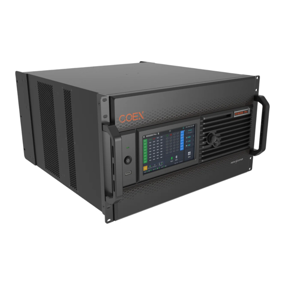
Page 6: Appearance
Press the knob to confirm the operation. Hold down the knob and BACK button simultaneously for 5s or longer to lock or unlock the buttons and screen. BACK Go back to the previous menu or cancel the current operation. www.novastar.tech... -
Page 7: Rear Panel
23.98 / 24 / 25 / 29.97 / 30 / 47.95 / 48 / 50 / 59.94 / 60 / 71.93 / 72 / 75 / 100 / 119.88 / 120 / 143.86 / 144 / 240 Hz Support HDR10 and comply with the SMPTE ST 2084 and SMPTE ST 2086 standards. www.novastar.tech... - Page 8 Support HDR10 and comply with the SMPTE ST 2084 and SMPTE ST 2086 standards. Support HLG. EDID Support standard resolutions, up to 3840×2160@60Hz. management Support custom input resolutions. HDCP Support HDCP 2.3, backwards compatible with HDCP2.2/ HDCP 1.4/ HDCP 1.3. www.novastar.tech...
- Page 9 50 meters are supported. MX_1×SMPTE ST 2110 input card MX_1×NDI input card Output Card MX_4×10G_Fiber output card Type Description OPT 1-4 10G optical ports Support single-mode and multi-mode optical fiber modules, with a maximum transmission distance of 10km. www.novastar.tech...
- Page 10 A single optical port/A Single card can load up to 8 channels of 5G Ethernet ports The maximum load of a single 5G Ethernet port is as follows: − 8bit@60Hz: 2,592,000 pixels − 10bit@60Hz: 2,073,000 pixels − 12bit@60Hz: 1,728,000 pixels www.novastar.tech...
- Page 11 For standard Genlock signal generators, up to 20 MX20 devices can be cascaded. An auxiliary connector that connects to the central control device (RS232) (Reserved) SPDIF A digital audio output (Reserved) MX_MVR output card Power Type Description 100-127V~/200-240V~, An AC power input connector and switch 15A/10A, 50/60Hz www.novastar.tech...
-
Page 12: Applications
5G receiving cards such as CA50E Note It would not be possible to build both 1G and 5G solutions with an MX6000 Pro at the same time. 3.2 1G Solution (MX_4x10G_Fiber Output Card) This diagram is an example of four input cards and one MX_4x10G_Fiber output card installed on an MX6000 Pro. -
Page 13: Solution (Cx_1X40G_Fiber Output Card)
MX6000 LED Display Controller User Manual 3.3 5G Solution (CX_1x40G_Fiber Output Card) This diagram is an example of four input cards and one CX_1x40G_Fiber output card installed on an MX6000 Pro. The actual application may vary. www.novastar.tech... -
Page 14: Vmp Operations
MX6000 LED Display Controller User Manual VMP Operations Users can only perform some basic operations on the LCD screen of MX6000 Pro. To perform more operations, please install Vision Management Platform (VMP) on the control PC. 4.1 Connect to VMP... -
Page 15: Device Management
You can also right-click a device or device group in the device list and select Import from the pop-up menu. Select a local project file and click Open. After successful device matching, a dialog box as shown in Figure 4-3 is displayed. Figure 4-3 Matching devices Click OK. www.novastar.tech... -
Page 16: Manage Device Groups
Enhance system reliability by establishing a primary controller and backup controller, allowing the backup controller to take over responsibility in case of primary controller failure. From the menu bar, choose Tools > System Backup to open the System Backup dialog box. www.novastar.tech... -
Page 17: Screen Configuration
Select a primary controller and a backup controller from the drop-down options respectively, and then click Add. The backup list will display the added backup information. To delete the backup information, click After the settings, click OK. 4.4 Screen Configuration 4.4.1 New Screen Select the controller from the device list and then select Layout. www.novastar.tech... -
Page 18: Configure Screen Topology
Select multiple screens: Hold Ctrl and click on the screen names. 4.4.2 Configure Screen Topology Select the controller from the device list and then select Layout. www.novastar.tech... - Page 19 The cabinets will be automatically connected when you are adding them, as shown in Figure 4-10. The Ethernet port's load capacity information will be displayed, as shown in Figure 4-11. The properties area will display the cabinet information, as shown in Figure 4-12. Figure 4-10 Cabinets connected automatically www.novastar.tech...
- Page 20 For cabinets that have the same size and consecutive serial numbers, if you want to change the cabinet connection topology, select the cabinets and then select a quick topology under Quick topo in the properties area, as shown in Figure 4-13. For other cabinets, skip this step. Figure 4-13 Quick topology www.novastar.tech...
- Page 21 − Snap to Grid: The cabinet will be snapped to the grid. Use the function menus on the menu bar − Edit menu − View menu www.novastar.tech...
-
Page 22: Set Card Backup
Set the cabinet topology for other canvases. 4.4.3 Set Card Backup Select the controller from the device list and then select Layout. In the properties area, select a backup for the card. www.novastar.tech... -
Page 23: Set The Cabinet
Select a test pattern from the drop-down list of Test Pattern to perform screen aging test and troubleshoot problems. Set Image for Abnormal Situations Select an option from the No Data signal drop-down list. Blackout: The screen displays a black image. Last Frame: The screen always displays the last frame. www.novastar.tech... -
Page 24: Input Source Configuration
Right-click a layer, select Source from the displayed menu, and select another source. Adjust layer size and position − Select a layer and set the layer size and coordinates in the properties area. You can also bring the layer to front or send it to back. www.novastar.tech... -
Page 25: Set External Sources
Set DP 1.4 Mode Select an option from the drop-down list to calculate the layer resources for the DP 1.4 connector. 8192*2160@60Hz: Up to 2 layers can be added. 4096*2160@60Hz: Up to 4 layers can be added. www.novastar.tech... - Page 26 Quantization Range. Then, in the Color area, drag the sliders to adjust the parameter values. The override parameter will be used in the calculation of color adjustment. Select From Input and the software will read the attribute value that comes with the input source. Figure 4-20 InfoFrame Override www.novastar.tech...
- Page 27 To set HDR parameters, the hardware must support HDR and the HDR10 or HLG sources must be prepared. Select an HDR format from the drop-down list of Format and set related parameters. Select Auto and the software will read the attribute value that comes with the input source. www.novastar.tech...
-
Page 28: Set Internal Sources
Source. Select an internal source from the source list and do the following as required. Set the Image Select an image and set the Grayscale, Gradient Stretch, Speed, and Space. The adjustable parameters for each image may vary based on the interface. Static images Dynamic images www.novastar.tech... -
Page 29: Display Correction
Image: Set which image the screen displays. To display the image of current input source, click and hold it. Select a correction mode. Figure 4-25 Select mode (seams) Cabinet Seams: Correct the seams of cabinets. LDM Seams: Correct the seams of the modules. www.novastar.tech... -
Page 30: Correct Multi-Batch Cabinets/Modules
If brightness correction has been done for the screen, the screen brightness can be adjusted in nits. Otherwise, it can be adjusted only in percentage. Select the controller from the device list and then select Correction. Select the Modules tab in the properties pane. Set the display content. www.novastar.tech... - Page 31 Figure 4-30 Cabinet structure override In the topology area, click or click and drag the mouse to select the cabinets or modules to be corrected. Drag the slider to adjust chroma. Figure 4-31 Adjustment Restore: Restore the configuration to the last saved. www.novastar.tech...
-
Page 32: Lock And Unlock Correction Page
Replace a color with another color according to the settings. Notice It is recommended to choose color with higher saturation for replacement to achieve better outcome. Operating Procedure Select the controller from the device list and then select Processing. Figure 4-33 Color Processing www.novastar.tech... -
Page 33: 14Ch Color Correction
Select the controller from the device list and then select Processing. Set the 14h Color Correction to Click a value of a color to enable the editing and change the value, , for example. Figure 4-35 14CH Color Correction www.novastar.tech... -
Page 34: Set Color Curves
Select the controller from the device list and then select Processing. Click anywhere in the Load 3DLUT File area, select a file and open it. Figure 4-37 Loading 3D LUT file Set the 3D LUT to and drag the slider to adjust the strength of the 3D LUT. www.novastar.tech... -
Page 35: Screen Settings
In the Image Quality tab, set the brightness and gamma value. Figure 4-40 Brightness and gamma adjustments 4.8.1.2 Set LED Image Booster Set the LED Image Booster function to improve the precision and accuracy of the image color and gradation and realize free switching of the display color gamut. www.novastar.tech... -
Page 36: Apply Calibration Effect
Select the controller from the device list and then select Screen Settings. In the Image Quality tab, set the Calibration switch to to make the screen apply the calibration effect made by the calibration platform. Figure 4-42 Calibration 4.8.1.4 Set Thermal Compensation Adjust the application intensity of the thermal coefficients. www.novastar.tech... -
Page 37: Adjust Eotf
Select the controller from the device list and then select Screen Settings. In the Output tab, select an option from the drop-down list of Bit Depth. If Auto is selected, the output bit depth is the same as the input bit depth. Figure 4-45 Output bit depth www.novastar.tech... -
Page 38: Set Sync Parameters
Set the number of frames and the display mode of each frame. Take the above Figure 4-47 as an example. The parameters are described as follows: Frame Multiplication: After the current frame rate (59.94) is multiplied by 3, it is 179.82 Hz. Three frames are output in 1/59.94 second. www.novastar.tech... -
Page 39: Set Shutter Fit
Only the main layer supports 3D effect. Related Information To use the 3D function, specified 3D glasses are needed. Please contact NovaStar technical support. Operating Procedure Select the controller from the device list and then select Screen Settings. In the Output tab, set 3D to Figure 4-49 3D Set the relevant parameters. -
Page 40: Check The Load
This setting ensures that the switching between left and right eye images of the 3D glasses is in sync with the switching between the left and right eye images on the display. This parameter is applicable to both the NovaStar and third-party emitters. 4.8.2.6 Check the Load Select the controller from the device list and then select Screen Settings. -
Page 41: Apply Presets
Figure 4-52 Apply presets 4.9.3 Manage Presets Select the controller from the device list and then select Preset and do the following operations as needed. Modify a Preset Select a preset. In the properties area, change the related information and click Save. www.novastar.tech... -
Page 42: Import And Export Presets
Click Export, select a file page, set a file name, and click Save. 4.10 Screen Monitoring 4.10.1 Check Device Status Select the controller from the device list and then select Monitor. Click the function icons on the left to check the related information www.novastar.tech... -
Page 43: Check Monitoring Records
Cabinet section of the properties area. You can also blackout, freeze, or enable test patterns for cabinets under the Cabinet Settings section. 4.10.2 Check Monitoring Records Select the controller from the device list and then select Preset. At the bottom of the page, do the operation as needed. www.novastar.tech... -
Page 44: Calibration Coefficient Management
(0, 0) point of the canvas. − To use the database file, you should prepare it in advance, and the resolutions of the configured screen and the screen in the database must be the same. To upload cabinet coefficients, make sure: www.novastar.tech... - Page 45 Figure 4-57 Select mode In the Coefficient Management area, click and select the target calibration data file (.db) from the local computer. The coefficient types in the file will be read automatically. You can select the range of coefficient types as needed. www.novastar.tech...
-
Page 46: Edit Calibration Coefficients
In the displayed window, select the target pixels and enter the parameters in the Coefficient Management area to adjust the proportion relationship of the red components, green components and blue components in RGB The calibration coefficients of the selected pixels will be overridden and changed to the values you set。 www.novastar.tech... -
Page 47: View Calibration Effect
In the Display area, you can adjust the screen brightness to clearly see the actual calibration effect change at each grayscale. You can also switch the color to see the uniformity of a single color and the entire display image. Figure 4-61 Set display content Brightness: Adjust the screen brightness. www.novastar.tech... -
Page 48: Save Calibration Coefficients
During coefficient saving, if the receiving cards go offline, the saving will fail. Operating Procedure Save the calibration coefficients of the current screen, cabinet or module to the receiving card to avoid calibration effect loss due to power failure. www.novastar.tech... -
Page 49: Read Back Calibration Coefficients
In the device list on the left, select the desired controller. From the menu bar, choose Tools > Coefficient Management. In the Select Mode area, select the reading range as needed, including Screen, Cabinet, LDM and Pixel. Figure 4-66 Selecting working mode In the Coefficient Management area, click Read. www.novastar.tech... -
Page 50: Export Calibration Coefficients
In the Coefficient Management area, click Export. Select a file path on the pop-up dialog box and click Save. In the pop-up Export Coefficients window, set the relevant parameters and click OK to export the coefficients of the screen to a file (.db). www.novastar.tech... -
Page 51: Screen Maintenance
From the menu bar, choose Tools > Maintain and do the following operations as needed. Figure 4-70 Controller maintenance Operations in Device List In the device list, right-click a controller. In the pop-up menu, select Controller Properties to open its dialog box. www.novastar.tech... - Page 52 Upgrade the firmware program Click Upgrade, select the firmware program file (.img) or .zip file and click Open. On the displayed window, double-check the uploaded file name and version and click Update to start upgrading. www.novastar.tech...
-
Page 53: Maintain Cabinets
.rpkg file for future use. Operating Procedure From the menu bar, choose Tools > Maintain and select the Cabinet tab. In the device list, select the target controllers and perform the following operations on the cabinets as needed. www.novastar.tech... - Page 54 On the Cabinet tab page, select one or multiple cabinets, click Update, and select an update method. Click Import and upload the file. To upload NCP file, select NCP File. To upload firmware program, select Firmware. To upload configuration file, select Config File. www.novastar.tech...
-
Page 55: Software Settings
To add multiple devices of the same model, click Batch Add. Figure 4-73 Add controller Select MX6000 Pro from the drop-down list of Controller Model. Click and then select input and output cards in the pop-up window. Click OK once you are done. -
Page 56: Change Language And Temperature Scale
From the menu bar, choose Settings > Cabinet Library. Click Manage Packs and do the following operations as needed to manage the cabinet library files. Figure 4-76 Cabinet library Upload NCP File Click Add. On the displayed window, click Upload File. www.novastar.tech... - Page 57 Sync NCP files between devices Select the files to be synced (multiple files can be selected), and click Sync NCP. On the displayed window, select the devices to which the files are synced (multiple devices can be selected). Click Sync. www.novastar.tech...
-
Page 58: Check User Manual
4.13.5 14.4 Check Software Information From the menu bar, choose Help > About and check the software information. 4.13.6 Check Keyboard Shortcuts From the menu bar, choose Help > Keyboard Shortcuts and check the commonly used software operation shortcuts. www.novastar.tech... -
Page 59: Front Screen Panel
Table 5-1 Home screen descriptions Area Content Description Top line MX6000 Pro The device name. The name can be changed in VMP software. The device button and touchscreen lock status. When the icon is displayed: The buttons are locked. - Page 60 Green: The temperature is normal. Yellow: Temperature alarm. The temperature has exceeded the threshold range. Red: Temperature alarm. The temperature has exceeded the threshold range significantly. Right Genlock The sync signal currently used. side Screens The number of screens with load. www.novastar.tech...
-
Page 61: Main Menu
Set internal source, check external input source information, and configure EDID and HDR parameters for external input sources. Configure network parameters. Set LCD screen timeout and brightness, set system language and temperature scale, check firmware information, and restore factory settings. Perform device diagnostics, view and export logs, and check device status. www.novastar.tech... -
Page 62: Screen
Figure 5-5 Set screen status Select Blackout or Freeze and then press the knob to toggle on or off the switch. : Enabled. The screen display will turn black or freeze, but the playback will not be interrupted. www.novastar.tech... -
Page 63: Input
Select Resolution, Frame Rate, and Bit Depth in sequence and set a value for each in the pop-up dialog box. After the settings are done, click Apply. 5.3.2 Check Input Source Information Select Input from the main menu to access the input source list. Select an input source to access the Information tab. www.novastar.tech... -
Page 64: Set Edid
Select an input source to open the parameter settings. Navigate to the EDID tab. Figure 5-8 EDID Select Resolution and Frame Rate in sequence and set a value for each in the pop-up dialog box. After the settings are done, click Apply. www.novastar.tech... -
Page 65: Set Hdr
Max CLL Override: Enable or disable Max CLL override. Max CLL: The max content light level. 5.4 Communication Select Communication from the main menu to access the settings interface. www.novastar.tech... -
Page 66: Settings
Figure 5-11 Configure LCD screen Select Auto Lock LCD and set a value in the pop-up dialog box. Select LCD Brightness and adjust the value. 5.5.2 Setting Language Select Settings from the main menu to access the settings interface. www.novastar.tech... -
Page 67: Set Temperature Scale
Select Settings from the main menu to access the settings interface. Select Temp Scale and then select Celsius(℃) or Fahrenheit(℉) from the pop-up dialog box. Figure 5-13 Set Temperature Scale 5.5.4 Check Firmware Information Select Settings from the main menu to access the settings interface. www.novastar.tech... -
Page 68: Factory Reset
Figure 5-15 Factory Reset 5.6 Maintenance 5.6.1 Diagnostics To export the diagnostics log, insert a USB drive to the USB port on the front panel of the device. Select Maintain from the main menu to access the settings interface. www.novastar.tech... -
Page 69: View And Export Logs
Figure 5-17 Device log Select Export to export the logs into a USB drive. 5.6.3 Check Device Status Select Maintain from the main menu to access the settings interface. Navigate to the Status tab to check the device status. www.novastar.tech... - Page 70 MX6000 LED Display Controller User Manual Figure 5-18 Check device status www.novastar.tech...
-
Page 71: Specifications
Please prevent the product from water intrusion and do not wet or wash the product. Noise Level (typical at 25° C/77° F) 53 dB (A) The amount of power consumption may vary depending on various factors such as product settings, usage, and environment. www.novastar.tech... -
Page 72: Video Source Specifications
4096×2160@60Hz YCbCr 4:4:4 YCbCr 4:2:2 12bit RGB 4:4:4 4096×2160@50Hz YCbCr 4:4:4 YCbCr 4:2:2 4096×2160@60Hz DP 1.4 8bit RGB 4:4:4 7680×4320@30Hz YCbCr 4:4:4 YCbCr 4:2:2 10bit RGB 4:4:4 7680×4320@24Hz YCbCr 4:4:4 YCbCr 4:2:2 7680×4320@30Hz 12bit RGB 4:4:4 5120×2160@60Hz YCbCr 4:4:4 www.novastar.tech... - Page 73 MX6000 LED Display Controller User Manual Input Bit Depth Sampling Format Max Input Resolution YCbCr 4:2:2 7680×4320@30Hz 12G-SDI 10bit YCbCr 4:2:2 4096×2160@60Hz www.novastar.tech...
-
Page 74: Ethernet Port Load Capacity
8bit: Load capacity × 24 × Frame rate < 1000 × 1000 × 1000 × 0.95 10bit: Load capacity × 48 × Frame rate < 1000 × 1000 × 1000 × 0.95 12bit: Load capacity × 48 × Frame rate < 1000 × 1000 × 1000 × 0.95 www.novastar.tech... -
Page 75: Solution (Cx_1X40G_Fiber Output Card)
Frame Rate / Bit 8bit 10bit 12bit Depth 24Hz 6,480,000 5,182,500 4,320,000 25Hz 6,220,800 4,975,200 4,147,200 30Hz 5,184,000 4,146,000 3,456,000 50Hz 3,110,400 2,487,600 2,073,600 60 Hz 2,592,000 2,073,000 1,728,000 120Hz 1,296,000 1,036,500 864,000 144Hz 1,080,864 864,441 720,576 240Hz 648,000 518,250 432,000 www.novastar.tech...
Need help?
Do you have a question about the MX6000 Pro and is the answer not in the manual?
Questions and answers