NovaStar MCTRL660 PRO User Manual
Independent controller
Hide thumbs
Also See for MCTRL660 PRO:
- User manual (39 pages) ,
- Quick start manual (2 pages) ,
- User manual (34 pages)

Related Manuals for NovaStar MCTRL660 PRO


Summary of Contents for NovaStar MCTRL660 PRO
- Page 1 MCTRL660 PRO Independent Controller User Manual Product Version: V1.3.0 Document Number: NS110100731...
- Page 2 Xi’an NovaStar Tech Co., Ltd. Statement You are welcome to use the product of Xi’an NovaStar Tech Co., Ltd. (hereinafter referred to as NovaStar). This document is intended to help you understand and use the product. For accuracy and reliability, NovaStar may make improvements and/or changes to this document at any time and without notice.
-
Page 3: Change History
MCTRL660 PRO Independent Controller User Manual Change History Change History Version Hardware Release Date Description Version V1.3.0 V1.0.3.0 2019-03-04 Added the Backup & Restore function for Web control. Changed the location of color depth function on Web control UI. -
Page 4: Table Of Contents
MCTRL660 PRO Independent Controller User Manual Contents Contents Change History ..........................ii 1 Overview ............................1 2 Features ............................2 Features ............................... 2 Video Source Features ..........................2 3 Applications ........................... 4 4 Cascading Devices ........................6 5 Hardware Structure........................7 Appearance .............................. - Page 5 MCTRL660 PRO Independent Controller User Manual Contents Image Mirroring ............................22 Backup and Restore ..........................24 Advanced Settings ............................. 24 7.8.1 Mapping Function ........................... 25 7.8.2 Loading RCFG Files ..........................25 7.8.3 Alarm Threshold Settings........................26 7.8.4 Image Settings ............................26 7.8.5 Saving to RV Card ..........................
-
Page 6: Overview
Pixel level brightness and chroma calibration Monitoring of inputs Multiple MCTRL660 PRO units can be cascaded. The MCTRL660 PRO is mainly used for the rental and fixed fields, such as concerts, live events, security monitoring centers, Olympic Games and various sports centers. www.novastar.tech... -
Page 7: Features
Supports individual Gamma adjustment for RGB when the color depth of input source is 10-bit or 12-bit. Monitoring of inputs One-click backup and recovery Multiple MCTRL660 PRO units can be cascaded. Video Source Features Features Input Connector Color Depth Sampling Format Maximum Input Resolution... - Page 8 MCTRL660 PRO Independent Controller User Manual 2 Features The Gamma value can be adjusted for 8-bit input sources and cannot be adjusted for 10-bit or 12-bit input sources. www.novastar.tech...
-
Page 9: Applications
User Manual 3 Applications Applications The MCTRL660 PRO can work as a sending card or fiber converter, meeting multiple application needs. Scenario 1: Application of Sending Card Mode On the OLED menu screen, choose Working Mode > Sending Card. This mode uses the optical ports or Gigabit Ethernet ports to output video signals. - Page 10 MCTRL660 PRO Independent Controller User Manual 3 Applications Figure 3-2 Application of fiber converter mode Scenario 3: Application of Dual-Output Working Mode Set the working mode for the two devices respectively, as shown in Figure 3-3. Device 1 uses the optical ports and Gigabit Ethernet ports to output video signals at the same time.
-
Page 11: Cascading Devices
Cascading Devices The control computer needs to control multiple MCTRL660 PRO devices. Cascade devices via USB IN and USB OUT ports of the MCTRL660 PRO devices. Up to 8 devices can be cascaded. Multiple MCTRL660 PRO devices need to output image simultaneously. -
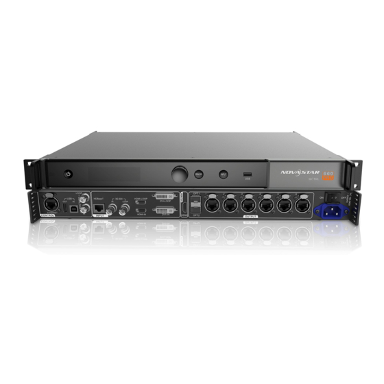
Page 12: Hardware Structure
MCTRL660 PRO Independent Controller User Manual 5 Hardware Structure Hardware Structure Appearance 5.1.1 Front Panel Description Operating indicator Green: The device is running normally. Red: The device is in standby mode. Standby button OLED operation screen Function knob BACK button: Press to go back to the previous menu. - Page 13 MCTRL660 PRO Independent Controller User Manual 5 Hardware Structure Type Single-link DVI connector Custom resolutions supported: Maximum width: 3840 pixels Maximum height: 2560 pixels Supported standard resolutions: 1024×768@(24/30/48/50/60/72/75/85/100/120)Hz 1280×1024@(24/30/48/50/60/72/75/85)Hz DVI IN 1366×768@(24/30/48/50/60/72/75/85/100)Hz 1440×900@(24/30/48/50/60/72/75/85)Hz 1600×1200@(24/30/48/50/60)Hz 1920×1080@(24/30/48/50/60)Hz 1920×1200@(24/30/48/50/60)Hz 2560×960@(24/30/48/50)Hz 2560×1600@(24/30)Hz...
- Page 14 Input Genlock sync signal to ensure synchronization and same refresh rate between the output signals of cascaded MCTRL660 PRO units and the external Genlock input signal. Genlock loop output connector. Up to 8 MCTRL660 PRO units can Control GENLOCK LOOP be cascaded.
-
Page 15: Dimensions
MCTRL660 PRO Independent Controller User Manual 5 Hardware Structure Dimensions Unit: mm www.novastar.tech... -
Page 16: Home Screen
User Manual 6 Home Screen Home Screen Sending Card Mode In the sending card mode, the home screen of the MCTRL660 Pro is shown below. Description Device name Alternatively display the resolution and color depth of the current input source when there are input sources accessed. -
Page 17: Fiber Converter Mode
The voltage alarm status, temperature alarm status and backup status are displayed in the same position on the home screen and the alarm statuses have priority. Fiber Converter Mode In the fiber converter mode, the home screen of the MCTRL660 Pro is shown below. www.novastar.tech... - Page 18 MCTRL660 PRO Independent Controller User Manual 6 Home Screen Description Device name Display the device IP address and sending card name alternatively. The sending card name can be customized in NovaLCT. See 8.5 Customizing Sending Card Name. The OPT1 port is the master input/output optical port, corresponding to the 6 Gigabit Ethernet ports.
- Page 19 MCTRL660 PRO Independent Controller User Manual 6 Home Screen Description 3 seconds to lock or unlock the buttons. When the buttons are locked, any button operations will be disabled and the icon will appear on the home screen. www.novastar.tech...
-
Page 20: Menu Operations
MCTRL660 PRO Independent Controller User Manual 7 Menu Operations Menu Operations The MCTRL660 PRO is powerful and easy to use. You can quickly configure the LED screen to light it up and display the entire input source following steps in 7.1 Quick Screen Configuration. -
Page 21: Step 2 Setting Input Resolution
Step 1 On the home screen, press the knob to enter the menu. Step 2 Choose Input Settings > Preset Resolution to enter its submenu. Step 3 Select a resolution and a refresh rate, and press the knob to apply them respectively. The MCTRL660 PRO supports the following preset resolutions. 1024×768@(24/30/48/50/60/72/75/85/100/120)Hz ... -
Page 22: Step 3 Setting Color Depth
MCTRL660 PRO Independent Controller User Manual 7 Menu Operations Figure 7-3 Custom resolution Step 2 On the home screen, press the knob to enter the menu. Step 3 Choose Input Settings > Custom Resolution to enter its submenu and set the screen width, height and refresh rate. -
Page 23: Brightness Adjustment
MCTRL660 PRO Independent Controller User Manual 7 Menu Operations Step 1 On the home screen, press the knob to enter the menu. Step 2 Choose Screen Settings > Quick Config to enter its submenu. Step 3 Enable Quick Config and set the parameters. -
Page 24: Screen Settings
MCTRL660 PRO Independent Controller User Manual 7 Menu Operations Screen Settings Configure the LED screen to ensure the screen can display the whole image normally. Screen configuration methods include quick, advanced and auto configurations. There are constrains on these methods, explained as below. -
Page 25: Image Offset
MCTRL660 PRO Independent Controller User Manual 7 Menu Operations Figure 7-8 Each Ethernet port loading only one row of cabinets Figure 7-9 Each Ethernet port loading only one column of cabinets Figure 7-10 Auto configuration Step 1 On the home screen, press the knob to enter the menu. -
Page 26: Input Settings
MCTRL660 PRO Independent Controller User Manual 7 Menu Operations Figure 7-11 Image offset Step 1 On the home screen, press the knob to enter the menu. Step 2 Choose Screen Settings > Image Offset to enter its submenu. Step 3 Set the Start X and Start Y values. -
Page 27: Image Mirroring
MCTRL660 PRO Independent Controller User Manual 7 Menu Operations Step 2 Choose Display Control to enter its submenu. Step 3 Select a control mode and press the knob to apply it. Image Mirroring Mirror images displayed on the LED screen. You can disable mirroring, mirror the image from left to right or from top to bottom. - Page 28 MCTRL660 PRO Independent Controller User Manual 7 Menu Operations Figure 7-15 Left-right mirroring of images loaded by Ethernet port 1 and 2 As shown above, after you set the mirroring mode as left-right for Ethernet ports 1-2, the entire image is mirrored horizontally, but only the areas of Ethernet ports 1-2 display the partial mirrored images.
-
Page 29: Backup And Restore
MCTRL660 PRO Independent Controller User Manual 7 Menu Operations Figure 7-18 Top-bottom mirroring of the entire image As shown above, after you set the mirroring mode as top-bottom for Ethernet ports 1- 4, the entire image is mirrored vertically. Backup and Restore Figure 7-19 Backup and restore ... -
Page 30: Mapping Function
MCTRL660 PRO Independent Controller User Manual 7 Menu Operations 7.8.1 Mapping Function When mapping function is enabled, each of the cabinets will display its cabinet No. and the No. of the Ethernet port that loads the cabinet. Note: Receiving cards used by the system must support mapping function. -
Page 31: Alarm Threshold Settings
MCTRL660 PRO Independent Controller User Manual 7 Menu Operations Figure 7-23 Importing configuration file of controller cabinet Step 3 Click Save the Change to HW to save the change to the controller. 7.8.3 Alarm Threshold Settings Set the alarm thresholds for device temperature and voltage. When a threshold is exceeded, its corresponding icon will be flashing, instead of displaying the value. -
Page 32: Saving To Rv Card
MCTRL660 PRO Independent Controller User Manual 7 Menu Operations Table 7-2 Image parameters Parameter Description Color temperature Range: 4000 K–9500 K, Stepping: 100 Red/Green/Blue Range: 0–255, Stepping: 1 Gamma Range: 1.0–4.0, Stepping: 0.1 Contrast Range: 0%–100%, Stepping: 1 Saturation Range: 0%–100%, Stepping: 1 Range: -180–180, Stepping: 1... -
Page 33: Low Latency
7.8.9 Low Latency The MCTRL660 PRO supports a low latency of less than 1 ms (when the start position of image is 0). Low latency is used to reduce the time delay between the input of video signal to the controller and the corresponding output. To enable low latency, you need to set the horizontal resolution loaded by a single Ethernet port less than or equal to 512 pixels. -
Page 34: Communication Settings
Check the hardware version of the controller. If a new version is released, you can update the firmware programs in NovaLCT or SmartLCT. Communication Settings Set the communication mode and network parameters of the MCTRL660 PRO. Communication mode: USB preferred and Local Area Network (LAN) preferred The controller connects to PC via the USB port or ETHERNET port. -
Page 35: Language
MCTRL660 PRO Independent Controller User Manual 7 Menu Operations Sending Card Mode On the OLED menu screen, set the working mode as Sending Card. Both the optical ports and Gigabit Ethernet ports can work as output ports to output video signals. -
Page 36: Operations On Pc
Operations on PC Individual Gamma Adjustment for RGB The MCTRL660 PRO supports individual Gamma adjustment for RGB when the color depth of input source is 10-bit or 12-bit, which effectively controls image non- uniformity under low grayscale and white balance offset to improve image quality. -
Page 37: Operations On Web Page
− to the same LAN Step 2 Set the PC (or mobile device) and the MCTRL660 PRO on the same LAN. Step 3 Obtain the IP address of the MCTRL660 PRO. Step 4 On the browser, enter the IP address to enter the operation page. -
Page 38: Software Operations On Pc
MCTRL660 PRO Independent Controller User Manual 8 Operations on PC Scenario 2: MCTRL660 PRO connected to PC (or mobile device) via LAN Software Operations on PC 8.3.1 NovaLCT Connect the MCTRL660 PRO to the control computer installed with NovaLCT V5.1.0 or later via USB port to perform screen configuration, brightness adjustment, calibration, display control, monitoring, etc. -
Page 39: Smartlct
8 Operations on PC 8.3.2 SmartLCT Connect the MCTRL660 PRO to the control computer installed with SmartLCT V3.2.0 or later via USB port to perform building-block cabinet configuration, seam brightness adjustment, real-time monitoring, hot backup, etc. For details on their operations, see SmartLCT User Manual. -
Page 40: Customizing Sending Card Name
MCTRL660 PRO Independent Controller User Manual 8 Operations on PC Customizing Sending Card Name Customize the sending card name. This name and the device IP address will be displayed on the home screen alternatively. Step 1 Run NovaLCT and choose User > Advanced Synchronous System User Login and log in as an advanced user. - Page 41 MCTRL660 PRO Independent Controller User Manual 8 Operations on PC Figure 8-4 Sending card name setting Step 4 Click Save to HW. www.novastar.tech...
-
Page 42: Specifications
MCTRL660 PRO Independent Controller User Manual 9 Specifications Specifications Input voltage 100 V–240 V AC Electrical Parameters Rated power consumption 20 W Temperature -20° C–60° C Operating Environment Humidity 10% RH–90% RH, non-condensing Storage Environment Temperature -25° C–125° C 550 mm × 440 mm × 175 mm...
Need help?
Do you have a question about the MCTRL660 PRO and is the answer not in the manual?
Questions and answers