Table of Contents
Advertisement
Quick Links
Advertisement
Table of Contents

Related Manuals for NovaStar MCTRL4K


Summary of Contents for NovaStar MCTRL4K
- Page 1 MCTRL4K LED Display Controller User Manual...
- Page 2 Added support for the 25Hz frame rate. Added the function of adaptation to decimal frame rates. Optimized HDR10 performance by adding low grayscale mode adjustment. Optimized the Mapping function illustration diagram. V1.0.0 2019-09-26 First release www.novastar.tech...
-
Page 3: Table Of Contents
MCTRL4K LED Display Controller User Manual Contents 1 Overview ......................................1 2 Appearance ...................................... 2 3 Applications ...................................... 5 4 Cascade Devices ..................................... 6 5 Home Screen ....................................7 6 Menu Operations ..................................... 9 6.1.1 Step 1: Set Input Mode ..............................9 6.1.2 Step 2: Set Input Resolution ............................ -
Page 4: Overview
Overview Introduction The MCTRL4K is an LED display controller with an ultra-large loading capacity developed by NovaStar. A single unit features a loading capacity of up to 4096×2160@60Hz. It supports any custom resolutions with a width or height up to 7680 pixels, meeting the on-site configuration requirements of ultra-long or ultra-wide LED displays. -
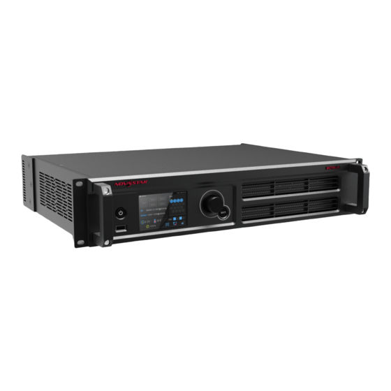
Page 5: Appearance
MCTRL4K LED Display Controller User Manual Appearance Front Panel Button/Connector Description Power button Power on or off the device. Connect to a USB drive. LCD screen Display the device status, menus, submenus and messages. Knob Select menus, adjust parameters, and confirm operations. - Page 6 MCTRL4K LED Display Controller User Manual 1920×1080@(24/25/30/48/50/60/72/75/85/100/120)Hz 1920×1200@(24/25/30/48/50/60/72/75/85/100/120)Hz 1920×2160@(24/25/30/48/50/60/72/75/85/100/120)Hz 2560×1600@(24/25/30/48/50/60/72/75/85/100/120)Hz 3840×1080@(24/25/30/48/50/60/72/75/85/100/120)Hz 3840×2160@(24/25/30/48/50/60)Hz No support for interlaced input sources HDMI 2.0 1x HDMI 2.0 Supported maximum resolution: 4096×2160@60Hz, supported minimum resolution: 800×600@30Hz Custom resolutions supported Maximum width: 7680 pixels (7680×1080@60Hz) Maximum height: 7680 pixels (1080×7680@60Hz)
- Page 7 Control ETHERNET Connect to the control computer. IN: 1x USB 2.0 (Type-B) Input port for cascading MCTRL4K units, or connecting to a PC for debugging USB IN-OUT OUT: 1x USB 2.0 (Type-A) Output port for cascading MCTRL4K units Up to 10 units can be cascaded.
-
Page 8: Applications
MCTRL4K LED Display Controller User Manual Applications The MCTRL4K can work in mosaic and multi-card modes, meeting multiple user application needs. Application 1: Mosaic Mode Figure 3-1 Application of mosaic mode Application 2: Multi-Card Mode Figure 3-2 Application of multi-card mode... -
Page 9: Cascade Devices
Cascade Devices The control computer controls multiple MCTRL4K devices. Cascade the MCTRL4K devices via their USB IN and USB OUT ports. Up to 10 devices can be cascaded. Multiple MCTRL4K devices output image simultaneously. Cascade the MCTRL4K devices via their GENLOCK IN and GENLOCK LOOP connectors. Up to 10 devices can be cascaded. -
Page 10: Home Screen
MCTRL4K LED Display Controller User Manual Home Screen After the MCTRL4K is powered on, its home screen appears, as shown in Figure 5-1. Figure 5-1 Home screen Area Description: The access status of inputs: On: Input available Off: Input unavailable The interval between unplugging and plugging the DP input must be greater than 5s. - Page 11 MCTRL4K LED Display Controller User Manual Area Description: The working status of the Ethernet ports Always on: The Ethernet port connection works and the port serves as primary. Off: The Ethernet port is not connected or the connection does not work.
-
Page 12: Menu Operations
MCTRL4K LED Display Controller User Manual Menu Operations The MCTRL4K is powerful and easy to use. You can quickly configure the LED screen to light it up and display the entire input source following the steps in Quick Screen Configuration. With other menu settings, you can further improve the LED screen display effect. -
Page 13: Step 2: Set Input Resolution
MCTRL4K LED Display Controller User Manual Enable: Convert RGB Limited to RGB Full. You are advised to enable this function when the input source has a limited color range. Note: You can enable the Limited to Full function only when the input source is RGB limited. When the input source is RGB full, enabling this function will cause grayscale loss. - Page 14 When the width or height of the output image is greater than 4092 pixels, the resolution must be customized via the NVIDIA graphics card. Step 1 Right-click on desktop. Step 2 Select NVIDIA Control Panel. Step 3 On the left panel, choose Display > Change resolution. On the right area, select NOVA MCTRL4K. www.novastar.tech...
- Page 15 Create Custom Resolution. In the Create Custom Resolution dialog box that appears, set the parameters. When you set the timing standard to Manual, use the MCTRL4K Ultra-High Resolution Settings Generator (Rev 1.1) to calculate the parameters, including active pixels, front porch (pixels), sync width (pixels), polarity, total pixels and refresh rate.
-
Page 16: Step 3: Quickly Configure The Screen
MCTRL4K LED Display Controller User Manual Step 5 Click Test. In the displayed dialog box indicating the test is successful, click Yes to save the custom resolution. Figure 6-4 Applying changes 6.1.3 Step 3: Quickly Configure the Screen Follow the steps below to complete quick screen configuration. -
Page 17: Advanced Configuration
The two methods cannot be enabled at the same time. After the screen is configured in NovaLCT, do not use any of the two methods on the MCTRL4K to configure the screen again. 6.3.1 Advanced Configuration Set parameters for each Ethernet port, including number of cabinet rows and columns (Cabinet Row QTY and Cabinet Col QTY), horizontal offset (Start X), vertical offset (Start Y), and data flow. -
Page 18: Image Offset
MCTRL4K LED Display Controller User Manual Figure 6-7 Advanced configuration Step 1 Choose Screen Settings > Advanced Config and press the knob. Step 2 In the caution dialog screen, select Yes to enter the advanced configuration screen. Step 3 Enable Advanced Config, select an Ethernet port, set the parameters for it, and apply the settings. -
Page 19: Mapping Function
MCTRL4K LED Display Controller User Manual Freeze: Make the LED screen always display the frame when frozen. The input source is still being played in the background. Test Pattern: Test patterns are used to check the display effect and pixel operating status. There are 8 test patterns, including pure colors and line patterns. -
Page 20: Load Cabinet Configuration Files
MCTRL4K LED Display Controller User Manual Figure 6-11 Illustration of mapping function Example: "P:01" stands for the Ethernet port number and "#001" stands for the cabinet number. Note The receiving cards used in the system must support the Mapping function. -
Page 21: Set Alarm Thresholds
6.5.7 HDR HDR is the abbreviation for High-Dynamic Range. HDR function can greatly enhance the display image quality, allowing for a more clear and vivid image when the device is used together with NovaStar A8s or A10s Plus receiving cards. - Page 22 MCTRL4K LED Display Controller User Manual When the input source is HLG, you can select one HLG mode from the 7 modes, namely HLG1 (300 nits) to HLG7 (1700 nits). Standard Parameter Description HDR10 Screen Peak Luma Range: 100 to 10000; step: 10...
- Page 23 MCTRL4K LED Display Controller User Manual Step 2 Under HDR Parameter Settings, select Enable. Step 3 Click the drop-down box to select an HDR standard (HDR10 and HLG supported). Step 4 Set the HDR parameters to adjust the display effect.
-
Page 24: Settings
In NovaLCT, the HDR and ClearView functions cannot be enabled at the same time. Using the HDR function will reduce the loading capacity of the MCTRL4K by half because the HDR input source is 10-bit. Please refer to the diagram above and work out a connection solution in advance. - Page 25 MCTRL4K LED Display Controller User Manual Figure 6-17 Application 1 Application 2: EMT200 connected between the controller and receiving card Figure 6-18 Application 2 3D Setting Procedure Step 1 Connect hardware devices according to the corresponding application. Step 2 Enable 3D function by using any of the following methods and set 3D parameters.
- Page 26 MCTRL4K LED Display Controller User Manual Press the BACK button to return to the main menu. Choose Advanced Settings > 3D Setting to enter its submenu. Enable 3D and set the video source format and eye priority mode. Video Source Format: Set the format to SBS (side-by-side), TAB (top-and-bottom) or Frame SEQ −...
- Page 27 MCTRL4K LED Display Controller User Manual Set 3D function parameters. Then, click Save to File to save the parameters you set as a file. Or, you can click Load from File to load an existing 3D configuration file. Mode Selection: This parameter is available when the video source is Dual DVI, as shown in the −...
- Page 28 MCTRL4K LED Display Controller User Manual Right Eye Start: When you set the video source format to side-by-side or top-and-bottom, you must − set the right eye start position. Signal Delay Time: When the input source is DP or HDMI, you must set this parameter. Please set −...
-
Page 29: Genlock Setting
Check the hardware version of the controller. If a new version is released, you can connect the controller to a PC to update the firmware programs in NovaLCT. Communication Settings Set the communication mode and network parameters of the MCTRL4K. Figure 6-22 Communication settings ... - Page 30 MCTRL4K LED Display Controller User Manual The controller connects to PC via USB port and Ethernet port. If USB Preferred is selected, the PC prefers to communicate with the controller via the USB port, or else via the Ethernet port.
-
Page 31: Operations On Pc
Low Latency The MCTRL4K supports a low latency of less than 1 ms (when the start position of image is 0). Low latency is used to reduce the time delay between the input of video signal to the controller and the corresponding output. - Page 32 MCTRL4K LED Display Controller User Manual Figure 7-2 Loading vertically Step 1 Run NovaLCT, choose Screen Configuration and enter the Sending Card tab page. Step 2 On the Screen Configuration page, select Enable Low Latency. Step 3 Click Save System Configuration File and Save.
- Page 33 MCTRL4K LED Display Controller User Manual Note The low latency function is supported when the input source is DP or HDMI. The low latency and Genlock functions cannot be enabled at the same time. When the low latency function is enabled, the offset of image cannot exceed the size of input source.
- Page 34 12bit The loading capacity of the MCTRL4K will be reduced by half. Operations on Web Page The MCTRL4K supports web control functions, so the screen configurations can be easily and quickly performed on a PC or mobile device. Note For LED screen configuration on web, the Google Chrome browser (Chrome 50 or later) is recommended.
-
Page 35: Environment Configuration
7.4.1 Environment Configuration Figure 7-5 Environment configuration diagram Step 1 Connect the MCTRL4K to a PC (or a mobile device) via Ethernet cable or router. Step 2 Obtain the IP address of the MCTRL4K from the top-right corner of home screen. -
Page 36: Novalct
MCTRL4K LED Display Controller User Manual Software Operations on PC 7.5.1 NovaLCT Connect the MCTRL4K to the control computer installed with NovaLCT V5.2.0 or later via USB port to perform screen configuration, brightness adjustment, calibration, display control, monitoring, etc. For details on their operations, see NovaLCT LED Configuration Tool for Synchronous Control System User Manual. -
Page 37: Smartlct
MCTRL4K LED Display Controller User Manual Step 1 Run the NovaLCT. On the menu bar, go to User > Advanced Synchronous System User Login. Enter the password and click Login. Step 2 Type the secret code “admin” to open the program loading page. -
Page 38: Specifications
MCTRL4K LED Display Controller User Manual Specifications Input voltage AC 100 V~240 V-50/60 Hz Electrical Parameters Rated power consumption 30 W Temperature -20° C to +60° C Operating Environment Humidity 10% RH to 90% RH, non-condensing Temperature -20° C to +70° C...
Need help?
Do you have a question about the MCTRL4K and is the answer not in the manual?
Questions and answers