NovaStar MCTRL660 PRO User Manual
Independent controller
Hide thumbs
Also See for MCTRL660 PRO:
- User manual (42 pages) ,
- Quick start manual (2 pages) ,
- User manual (39 pages)
Table of Contents
Advertisement
Quick Links
Advertisement
Table of Contents

Related Manuals for NovaStar MCTRL660 PRO


Summary of Contents for NovaStar MCTRL660 PRO
- Page 1 MCTRL660 PRO Independent Controller User Manual...
- Page 2 2019-01-25 Updated the appearance and dimensions diagrams. V1.1.0 2018-12-03 Optimized the description of ultra-high color depth input. Optimized the description of individual gamma adjustment for RGB. Optimized the description of low latency. V1.0.0 2018-09-26 First release www.novastar.tech...
-
Page 3: Table Of Contents
MCTRL660 PRO Independent Controller User Manual Contents 1 Overview ......................................1 2 Appearance ...................................... 2 3 Applications ...................................... 5 4 Cascade Devices ..................................... 7 5 Home Screen ....................................8 6 Menu Operations ..................................... 11 6.1.1 Step 1: Set Input Source ............................... 11 6.1.2 Step 2: Set Input Resolution ............................ -
Page 4: Overview
1920×1200@60Hz. Supporting image mirroring, this controller can present a variety of images and bring an amazing visual experience to users. The MCTRL660 PRO can work as a sending card and a fiber converter, and supports switching between the two modes, meeting more diversified market demands. -
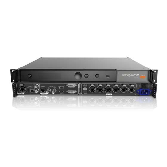
Page 5: Appearance
MCTRL660 PRO Independent Controller User Manual Appearance Front Panel Name Description Green: The device is running normally. Running Indicator Red: Standby Standby Button Power on or off the device. OLED Screen Display the device status, menus, submenus and messages. - Page 6 MCTRL660 PRO Independent Controller User Manual Custom resolutions supported Max width: 3840 pixels (3840×600@60Hz) Max height: 3840 pixels (800×3840@30Hz) HDCP 1.4 compliant Supported standard resolutions: 1024×768@(24/30/48/50/60/72/75/85/100/120)Hz 1280×1024@(24/30/48/50/60/72/75/85)Hz 1366×768@(24/30/48/50/60/72/75/85/100)Hz 1440×900@(24/30/48/50/60/72/75/85)Hz 1600×1200@(24/30/48/50/60)Hz 1920×1080@(24/30/48/50/60)Hz 1920×1200@(24/30/48/50/60)Hz 2560×960@(24/30/48/50)Hz 2560×1600@(24/30)Hz Do NOT support interlaced signal input.
- Page 7 MCTRL660 PRO Independent Controller User Manual IN: 1x type-B USB 2.0, used as the input port to cascade devices or connect to PC for device debug USB IN-OUT OUT: 1x type-A USB 2.0, used as the output port to cascade devices.
-
Page 8: Applications
MCTRL660 PRO Independent Controller User Manual Applications The MCTRL660 PRO can work as a sending card and fiber converter, meeting multiple application needs. Application 1: Sending Card Mode On the OLED menu screen, choose Working Mode > Sending Card. This mode uses the optical ports or Gigabit Ethernet ports to output video signals. - Page 9 MCTRL660 PRO Independent Controller User Manual Figure 3-3 Application of dual output mode www.novastar.tech...
-
Page 10: Cascade Devices
Cascade Devices The control computer controls multiple MCTRL660 PRO devices. Cascade the MCTRL660 PRO devices via their USB IN and USB OUT ports. Up to 8 devices can be cascaded. Multiple MCTRL660 PRO devices output image simultaneously. Cascade the MCTRL660 PRO devices via their GENLOCK IN and GENLOCK LOOP connectors. Up to 8 devices can be cascaded. -
Page 11: Home Screen
MCTRL660 PRO Independent Controller User Manual Home Screen Sending Card Mode In the sending card mode, the home screen of the MCTRL660 PRO is shown below. Description Device name Alternatively display the resolution and color depth of the current input source when there are input sources accessed. - Page 12 Fiber Converter Mode In the fiber converter mode, the home screen of the MCTRL660 PRO is shown below. Description Device name Alternatively display the device IP address and sending card name.
- Page 13 MCTRL660 PRO Independent Controller User Manual Description 1–6: Indicate Ethernet ports 1–6. LINK: Ethernet port connection status − Always on: The Ethernet port connection works. − Off: No Ethernet cable is connected or the connection does not work. ...
-
Page 14: Menu Operations
MCTRL660 PRO Independent Controller User Manual Menu Operations The MCTRL660 PRO is powerful and easy to use. You can quickly configure the LED screen to light it up and display the entire input source following the steps in Quick Screen Configuration. -
Page 15: Step 3: Set Input Bit Depth
MCTRL660 PRO Independent Controller User Manual Figure 6-2 Preset resolution Step 1 On the home screen, press the knob to enter the main menu. Step 2 Choose Input Settings > Preset Resolution to enter its submenu. Step 3 Select a resolution and refresh rate, and press the knob to apply them. -
Page 16: Step 4: Quickly Configure The Screen
MCTRL660 PRO Independent Controller User Manual Step 2 Choose Input Settings > Color Depth to enter its submenu, select a color depth, and press the knob to apply Table 6-1 Input bit depth adjustment Bit Depth Description 8bit The loading capacity of the device will not be reduced. -
Page 17: Quick Configuration
The three methods cannot be enabled at the same time. After the screen is configured in NovaLCT, do not use any of the methods on the MCTRL660 PRO to configure the screen again. 6.3.1 Quick Configuration Configure the whole LED screen uniformly and quickly. See Quick Screen Configuration. -
Page 18: Auto Configuration
MCTRL660 PRO Independent Controller User Manual 6.3.3 Auto Configuration Note: Each Ethernet port must load only a whole row or column of cabinets. Figure 6-8 Each Ethernet port loading only one row of cabinets Figure 6-9 Each Ethernet port loading only one column of cabinets... -
Page 19: Image Offset
MCTRL660 PRO Independent Controller User Manual Figure 6-10 Auto configuration Step 1 On the home screen, press the knob to enter the main menu. Step 2 Choose Screen Settings > Auto Config to enter its submenu. Step 3 Enable Auto Config and select a data flow. - Page 20 MCTRL660 PRO Independent Controller User Manual This function is disabled when the input source is SDI. Image mirroring and low latency cannot be enabled at the same time. Figure 6-13 Image mirroring Step 1 On the home screen, press the knob to enter the main menu.
- Page 21 MCTRL660 PRO Independent Controller User Manual Figure 6-16 Left-right mirroring of the entire image As shown in Figure 6-16, after you set the mirroring mode as left-right for Ethernet ports 1–4, the entire image is mirrored horizontally. Figure 6-17 Top-bottom mirroring of the image loaded by Ethernet port 1...
-
Page 22: Mapping Function
MCTRL660 PRO Independent Controller User Manual Backup and Restore Figure 6-19 Backup and restore Back up the system configuration to the controller. Restore the system configuration from the controller. Restore the receiving card configuration from the controller. -
Page 23: Load Cabinet Configuration Files
MCTRL660 PRO Independent Controller User Manual 6.7.2 Load Cabinet Configuration Files Before you begin: Save the cabinet configuration file (*.rcfgx or *.rcfg) to the local PC. Step 1 Run NovaLCT and choose Tools > Controller Cabinet Configuration File Import. Step 2 On the displayed page, select the currently used Ethernet port, click Add Configuration File to select and add a cabinet configuration file. -
Page 24: Save To Rv Card
MCTRL660 PRO Independent Controller User Manual Gamma Range: 1.0 to 4.0; step: 0.1 Contrast Range: 0% to 100%; step: 1% Saturation Range: 0% to 100%; step: 1% Range: –180 to +180; step: 1 6.7.5 Save to RV Card By using this function, you can: ... -
Page 25: Low Latency
MCTRL660 PRO Independent Controller User Manual 6.7.9 Low latency Supports a low latency of less than 1 ms (when the start position of image is 0). Low latency is used to reduce the time delay between the input of video signal to the controller and the corresponding output. The loading width of a single Ethernet port should be no greater than 512 pixels when low latency function is enabled. - Page 26 Reset: Reset the parameters to defaults. Working Mode The MCTRL660 PRO supports switching between the sending card mode and fiber converter mode. Figure 6-25 Working mode Sending Card Mode On the OLED menu screen, set the working mode as Sending Card. Either the optical ports or the Gigabit Ethernet ports can work as output ports to output video signals.
- Page 27 MCTRL660 PRO Independent Controller User Manual Fiber Converter Mode Only communication settings and working mode settings are available. The temperature and voltage alarm thresholds keep the last settings. On the OLED menu screen, set the working mode as Fiber Converter. The optical ports (for input/output) and Gigabit Ethernet ports (for output/input) are used to realize conversion between optical and electric signals.
-
Page 28: Operations On Pc
When the input bit depth is 8-bit, the individual gamma adjustment for RGB is realized by the AXs (V2.0) series receiving cards. Operations on Web Page The MCTRL660 PRO allows users to configure screens on a web page, making screen configuration much easier. www.novastar.tech... -
Page 29: Environment Configuration
Application 1: The MCTRL660 PRO and PC are connected with an Ethernet cable. − Application 2: The MCTRL660 PRO and PC (or mobile device) are connected to the same LAN via a router. Step 2 Connect the PC (or mobile device) and MCTRL660 PRO to the same LAN. -
Page 30: Novalct
Software Operations on PC 7.3.1 NovaLCT NovaLCT (V5.2.0 or later) communicates with the MCTRL660 PRO via USB cable, allowing for screen configuration, brightness adjustment, calibration, display control, monitoring, and more. For details, see NovaLCT LED Configuration Tool for Synchronous Control System User Manual. -
Page 31: Novalct
MCTRL660 PRO Independent Controller User Manual Figure 7-2 SmartLCT Firmware Update 7.4.1 NovaLCT In NovaLCT, perform the following steps to update the firmware. Step 1 Run the NovaLCT. On the menu bar, go to User > Advanced Synchronous System User Login. Enter the password and click Login. - Page 32 MCTRL660 PRO Independent Controller User Manual Figure 7-3 Home page Step 3 Under Sending Card Name Setting, select Enable Naming and click Rename. On the displayed Rename dialog box, enter a name and click OK. Figure 7-4 Importing controller cabinet configuration file Step 4 On the Controller Cabinet Configuration File Import page, click Save to HW.
-
Page 33: Specifications
MCTRL660 PRO Independent Controller User Manual Specifications Input voltage 100 V–240 V AC Electrical Specifications Rated power consumption 20 W –20° C to +60° C Operating Environment Temperature Humidity 10% RH to 90% RH, non-condensing –20° C to +70° C...
Need help?
Do you have a question about the MCTRL660 PRO and is the answer not in the manual?
Questions and answers