
Subscribe to Our Youtube Channel
Related Manuals for Teldat IMBER SMART


Summary of Contents for Teldat IMBER SMART
- Page 1 Advanced Industrial Router IMBER SMART User Manual Teldat Group, SA www.teldat.com...
- Page 2 IMBER SMART – Industrial Series User Manual REVISION HISTORY Revision Date Firmware Version Revision Details May 2018 Initial release. Aug 2018 Add Schedule Reboot, OpenVPN, IPsec Oct 2018 Add SSH, GRE, VRRP, Wi-Fi Client Add Data Roaming, IP Passthrough, SMS, GRE Layer2 Jun 2019 v1.1.0(278c6c6)
- Page 3 User Manual Trademarks and copyright Teldat Group and Imber and Teldat Group and Imber logos are the trademarks or registered trademarks in Spain and other countries worldwide. All other trademarks mentioned in this document are the property of their respective owners.
-
Page 4: Table Of Contents
IMBER SMART – Industrial Series User Manual Table of Contents Chapter 1 Safety Precautions ............................5 Risk identification ............................5 Installation and operation .......................... 5 Chapter 2 Product Overview ............................7 Overview ..............................7 Features and Benefits ..........................7 General Specifications ..........................8 Mechanical Specifications ........................ - Page 5 IMBER SMART – Industrial Series User Manual 5.5.4 IP Passthrough ..........................57 Applications .............................. 58 5.6.1 DDNS ..............................58 5.6.2 SMS ..............................59 5.6.3 Schedule Reboot ..........................63 5.6.4 GPS ..............................63 5.6.5 Call ..............................66 VPN ................................67 5.7.1 OpenVPN ............................
-
Page 6: Chapter 1 Safety Precautions
IMBER SMART – Industrial Series User Manual Chapter 1 Safety Precautions The following sections describe the safety precautions to take when handling your device. Read all installation instructions before using, installing, or connecting the system to the power source. Please check the User Information Guide that accompanies the equipment for any additional requirements. - Page 7 IMBER SMART – Industrial Series User Manual Installing and Grounding the Antenna WARNING: Do not locate the antenna near overhead power lines or other electric light or power circuits, or where it can come into contact with these circuits. When installing the antenna, exercise extreme care not to come into contact with these circuits, as they can cause serious injury or death.
-
Page 8: Chapter 2 Product Overview
Serial to IP communication. In addition, it has 2 digital input and 2 digital output channels for alarm applications. The IMBER SMART series router accepts a wide power input range (9 to 48 VDC) and has an integrated reverse-voltage protection mechanism for greater reliability. Its reliable data transmission features make it an advanced choice for universal wireless M2M applications. -
Page 9: General Specifications
IMBER SMART – Industrial Series User Manual 2.3 General Specifications Cellular Interface • Standards: FDD-LTE/TDD-LTE, WCDMA/UMTS/HSPA/HSPA+/EDGE/GPRS, • 2× SMA female antenna connector • 2x SIM (3.0V and 1.8V) Wi-Fi Interface • Standards: 802.11b/g/n, 300Mbps • 2x RP-SMA male antenna connector •... - Page 10 IMBER SMART – Industrial Series User Manual DI/DO Interface Type: 2 x DI + 2 x DO • Connector: terminal block • Isolation: 3KVDC or 2KVrms • Absolute maximum VDC: 36VDC • Absolute maximum ADC: 100mA • Other Interfaces 1× RST button •...
-
Page 11: Mechanical Specifications
IMBER SMART – Industrial Series User Manual 2.4 Mechanical Specifications Dimensions: 106mm x 106mm x 40mm (excluding antenna) Page 10 / 92... -
Page 12: Package Checklist
User Manual 2.5 Package Checklist The IMBER SMART series Router comes with the parts shown below. Please check to make sure all parts are included in the shipping box. NOTE: if any parts are missing or damaged, please contact your sales representative. -
Page 13: Order Information
IMBER SMART – Industrial Series User Manual 1x Stubby RP-SMA Wi-Fi antenna 1x Stubby 3G/4G cellular antenna 1x AC/DC power adapter (12VDC, 1.5A; EU/US/UK/AU depending on SKU) Note: Image used as reference 2.6 Order Information Model Part Number Description 4G LTE, Dual SIMs, 4 x Eth,... -
Page 14: Chapter 3 Installation
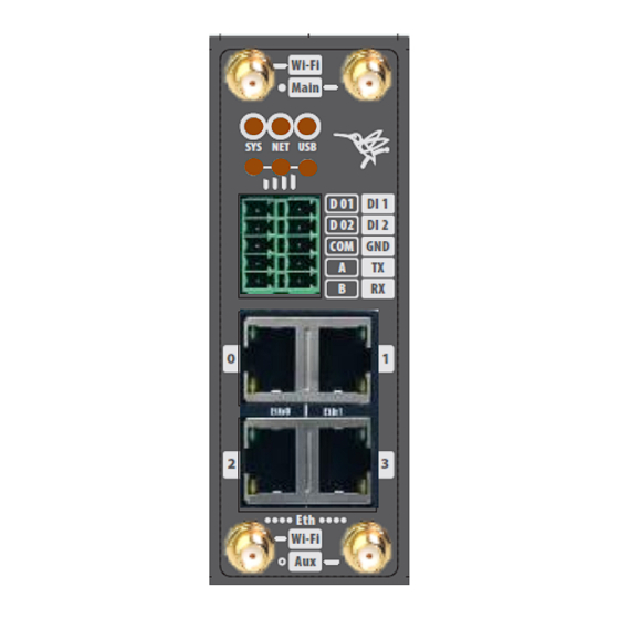
IMBER SMART – Industrial Series User Manual Chapter 3 Installation 3.1 Product Overview Front Panel • Wi-Fi Antenna ① MAIN Cellular Antenna ② LED Indicator ③ Serial port and DIDO ④ Ethernet port ⑤ Wi-Fi Antenna ⑥ AUX Cellular Antenna ⑦... -
Page 15: Led Indicators
IMBER SMART – Industrial Series User Manual 3.2 LED Indicators Name Color Status Description Slow blinking (500ms duration) Operating normally Fast blinking System booting Green Power is off Registers with a highest-priority network service (depends on the Radio, e.g., Radio supports LTE as highest-priority network). -
Page 16: Ethernet Port Indicator
IMBER SMART – Industrial Series User Manual 3.3 Ethernet Port Indicator Name Status Description Connection is established Blinking Data is being transmitted Link indicator Connection is not established NOTE:There are two LED indicators for each Ethernet port. Due to the chipset design, the IMBER SMART router will only light up the left-hand green one (Link indicator). -
Page 17: Reset Button
IMBER SMART – Industrial Series User Manual Power Input • Description V+ (Red line) Positive V- (Yellow line) Negative PGND 3.5 Reset Button Function Action Press the RST button for less than 3 seconds in operating status Reboot Press the RST button for 3 to 10 seconds until all LEDs blink a few times Factory Reset and then reboot the router manually. -
Page 18: Install Antenna
Connect the cellular antenna to the MAIN and AUX connectors on the unit. • NOTE: The IMBER SMART router supports dual antennas and has two antenna connectors, MAIN and AUX. The MAIN connector is for receiving and transmitting data while the AUX connector is for improving signal strength. -
Page 19: Din-Rail Mounting
IMBER SMART – Industrial Series User Manual 3.8 DIN Rail Mounting Attach the DIN-rail bracket to the router using four M3 x 6mm Phillips flat head screws. Insert the upper lip of the DIN-rail bracket onto the DIN-rail track. Lightly press the router towards the DIN-rail track until the bracket snaps into place. -
Page 20: Power Supply Installation
IMBER SMART – Industrial Series User Manual 3.10 Installing the Power Supply Remove the pluggable connector from the device and then loosen the screws for the locking flanges as required. Connect the wires from the power supply to the terminals. -
Page 21: Chapter 4 Access To Web Page
Chapter 4 Accessing the Web page 4.1 PC Configuration The IMBER SMART router has a DHCP server that automatically assigns an IP address to your PC. In some cases, however, you may need to change your PC’s network settings to enable it to accept the IP address from the IMBER SMART router. -
Page 22: Factory Default Settings
IMBER SMART router. 4.2 Factory Default Settings The IMBER SMART router supports a Web-based configuration interface for management. If this is your first time configuring the router, please refer to the default settings below. Username: admin Password: admin LAN IP Address: 192.168.5.1 (Eth0~Eth1/Eth3 bridge as LAN mode) -
Page 23: Login To Web Page
IMBER SMART – Industrial Series User Manual 4.3 Logging In to Web Page 1. Open a Web browser on your PC (Chrome and IE are recommended) and type 192.168.5.1 in the browser’s address bar. 2. Then use the default username and password (admin/admin) to log in to the router. -
Page 24: Chapter 5 Web Configuration
Chapter 5 Web Configuration 5.1 Web Interface The IMBER SMART router Web interface is divided into two sections. On the left you can see the main navigation menu, and on the right, the content area for each page. NOTE: Depending on the options installed in your unit, the navigation menu may contain fewer sections than those shown here. - Page 25 IMBER SMART – Industrial Series User Manual Reboot: reset the router with the power disconnected. • Logout: logout to the web authorization page. • Save: save the configuration on the current page. • Apply: apply the changes on the current page immediately.
-
Page 26: Overview
IMBER SMART – Industrial Series User Manual 5.2 Overview 5.2.1 Status Get system information for the router on this page. System Information Device Module • Displays the router model name. System Uptime • Displays the amount of time the system has been up in hours, minutes, and seconds. -
Page 27: Syslog
IMBER SMART – Industrial Series User Manual Active Link Information Link Type • Current interface for internet access. IP Address • Displays the IP address assigned to this interface. Netmask • Displays the subnet mask of this interface. Gateway •... -
Page 28: Link Management
IMBER SMART – Industrial Series User Manual Syslog Information Download Diagnosis • Downloads a Diagnosis file for analysis. Download Syslog • Downloads the complete syslog since the last reboot. Clear • Clears the syslog information displayed on the current page. - Page 29 IMBER SMART – Industrial Series User Manual Click to add a new priority interface. Click to edit the current interface settings. Click to delete the current interface. Connection Manager->Connection Priority • Displays the priority list for the default routing selection.
- Page 30 IMBER SMART – Industrial Series User Manual Connection Settings Priority • Displays the current index in the priority list. Connection Type • Select the available interface as the outbound link. NOTE: specify SIM1 carrier link as WWAN1, SIM2 carrier link as WWAN2.
- Page 31 IMBER SMART – Industrial Series User Manual Timeout • Enter timeout for receiving ping replies to determine if ICMP detections have failed. Retry Times • Specify the number of times that the system will retry if ICMP detections continue receiving no response.
-
Page 32: Cellular
IMBER SMART – Industrial Series User Manual 5.3.2 Cellular The IMBER SMART router’s main function is to connect to the Internet via a cellular modem. Cellular->Status Modem • Displays the type of modem module used for this WWAN interface. Registration •... - Page 33 International Mobile Subscriber Identity, as read from the SIM. This is the user’s network subscription. TX Bytes • Displays the total number of bytes sent since the unit was connected. The IMBER SMART router records this data on the same SIM card. A device reboot will not erase this data. RX Bytes •...
-
Page 34: Ethernet
IMBER SMART – Industrial Series User Manual SIM Card Settings SIM Card • Displays the current SIM card settings. Auto APN • Check this box to enable auto checking the Access Point Name provided by the carrier. Dial Number •... - Page 35 IMBER SMART – Industrial Series User Manual Ethernet->Status Ethernet Port Information • Displays the physical connection status of ports. Interface Information • Displays the name and MAC address of the Ethernet interfaces. DHCP Lease Table • Displays the DHCP client’s currently assigned IP address.
- Page 36 Enter the IP address of the secondary wan interface. Netmask • Enter the netmask of the secondary wan interface. The IMBER SMART router also supports setting the WAN connection type to Static IP and PPPoE mode. Page 35 / 92...
- Page 37 IMBER SMART – Industrial Series User Manual Ethernet->WAN->Static IP or PPPoE IP Address • Static address for this interface. It must be on the same subnet as the gateway. Netmask • This will be assigned by the gateway. Gateway •...
- Page 38 IMBER SMART – Industrial Series User Manual Ethernet->LAN Interface • Select the configured LAN port for this subnet. IP Address • Enter the LAN IP address for this interface. Netmask • Enter the subnet mask for this subnet. • Maximum Transmission Unit is the maximum packet size allowed to be transmitted. Usually, this should be left at the default value of 1500.
- Page 39 IMBER SMART – Industrial Series User Manual Relay Server • Enter the IP address of the DHCP relay server. IP Pool Start • When DHCP is enabled, external LAN devices connected to this unit will be assigned an IP address in this range.
- Page 40 IMBER SMART – Industrial Series User Manual Ethernet->LAN->Multiple IP Settings Interface • Select the configured LAN port for this subnet. IP Address • Enter multiple IP addresses for this interface. Netmask • Enter the subnet mask for this subnet. Ethernet->VLAN->VLAN Trunk Settings Interface •...
-
Page 41: Wi-Fi
User Manual 5.3.4 Wi-Fi The IMBER SMART router can either be used as a Wi-Fi Client or a Wi-Fi Access Point, but not at the same time. Select Wi-Fi (Access Point) from the main navigation menu to access the Wi-Fi page. - Page 42 IMBER SMART – Industrial Series User Manual Wi-Fi AP This page allows you to configure the Wi-Fi AP settings: Wi-Fi->Wi-Fi AP Enable • Checking this box will enable the Wireless interface. SSID • The SSID is the name given to identify the wireless local network. Devices connecting to the IMBER SMART router’s Wi-Fi access point will identify the Access Point using this SSID.
- Page 43 Select the Wi-Fi channel the module will transmit on. If there are other Wi-Fi devices in the area, make sure the IMBER SMART router is set on a different channel to those being used by the other access points. Available Channels will depend on the selected Band.
- Page 44 IMBER SMART – Industrial Series User Manual Wi-Fi Client Here you can see the Wi-Fi Client settings page: Page 43 / 92...
- Page 45 IMBER SMART – Industrial Series User Manual Wi-Fi->Wi-Fi Client Enable • Checking this box will enable the Wireless interface. Connect to Hidden SSID • Check this box to connect to a hidden SSID. SSID • SSID of an external access point.
-
Page 46: Industrial Interface
IMBER SMART – Industrial Series User Manual 5.4 Industrial Interface Tabs on the Industrial page allow you to set the configuration settings for Serial RS232 and RS485, Digital input and output. Select Serial & Digital IO from the main navigation menu to navigate to this page. - Page 47 IMBER SMART – Industrial Series User Manual Serial->Connection Enable • Displays the status of the current serial function. Port • Displays the serial type of the COM port. Baud Rate • Displays the serial port baud rate. Data Bits •...
- Page 48 IMBER SMART – Industrial Series User Manual Serial->Connection Settings Baud Rate • Select the serial port baud rate. Supported values are 300, 600, 1200, 2400, 4800, 9600, 19200, 38400, 57600, or 115200. Data Bits • Select a value from 7 or 8.
- Page 49 IMBER SMART – Industrial Series User Manual The window below displays different settings when you select UDP in the Protocol field: Serial->Connection Settings Local IP Address • Enter the IP Address of the local endpoint. Local Port • The port number assigned to the serial IP port on which communications will take place.
-
Page 50: Digital Io
IMBER SMART – Industrial Series User Manual 5.4.2 Digital IO This section allows you to set the Digital IO parameters. The Digital Input can be used for triggering alarms and the Digital Output for controlling slave devices, using a digital signal. - Page 51 IMBER SMART – Industrial Series User Manual Alarm ON Content • Specify the alarm on content to be sent out via SMS messages. Alarm OFF Content • Specify the alarm off content to be sent out via SMS messages Digital IO->Digital Output Enable •...
-
Page 52: Network
IMBER SMART – Industrial Series User Manual 5.5 Network 5.5.1 Firewall Firewall rules are security rulesets that implement control over users, applications, or network objects in an organization. You can use a firewall rule to create a blanket or specialized traffic transit rules based on your requirements. - Page 53 IMBER SMART – Industrial Series User Manual Firewall->ACL Description • Add a description for this rule. Chain • Specify the ACL forward rule. Choose between “FORWARD” and “INPUT”. Protocol • All: Any protocol number. TCP: TCP protocol. UDP: UDP protocol.
- Page 54 IMBER SMART – Industrial Series User Manual Local Address • Sets the LAN address of a device connected to one of the router’s LAN interfaces. Inbound requests will be forwarded to this IP address. Local Port • Sets the LAN port number range used when forwarding to the destination IP address.
-
Page 55: Route
IMBER SMART – Industrial Series User Manual Interface To Address • Specify the interface that connected to the host, e.g., lan0, lan1, lan2, lan3. Firewall->URL Filter • Enter the URL to block data traffic from entering the website, e.g., www.google.com. - Page 56 IMBER SMART – Industrial Series User Manual Route->Static Route Settings Description • Enter a description for the current static route rule. IP Address • Enter the IP address of the destination network. Netmask • Enter the subnet mask of the destination network.
-
Page 57: Vrrp
IMBER SMART – Industrial Series User Manual 5.5.3 VRRP The Virtual Router Redundancy Protocol (VRRP) is a computer networking protocol that automatically assigns available Internet Protocol (IP) routers to participating hosts. The VRRP router with the highest number becomes the virtual master router. VRRP router numbers range from 1 to 255, where 255 is usually used for highest priority and 100 for backup priority. -
Page 58: Ip Passthrough
IMBER SMART – Industrial Series User Manual 5.5.4 IP Passthrough IP Passthrough mode disables NAT and routing and passes the WAN IP address from the WAN interface to the device connected on the local Interface. It provides an alternative to Network Address Translation (NAT) when you want to make the router "transparent"... -
Page 59: Applications
IMBER SMART – Industrial Series User Manual 5.6 Applications 5.6.1 DDNS DDNS is a system that allows the domain name data of a device with multiple (dynamic) IP addresses held in a name server to be updated in real time. Consequently, users can connect to the device without having to track the IP addresses. -
Page 60: Sms
IMBER SMART – Industrial Series User Manual Check this box to enable the DDNS service. Provider • Select the DDNS provider from the list. Options are “DynDNS”, “no-ip”,”3322” and custom. DDNS Server • The internet address to communicate the Dynamic DNS information to. This option is available after selecting custom in the DDNS Provider field. - Page 61 IMBER SMART – Industrial Series User Manual Enable • Check this box to enable the SMS feature. Enable SMS Control • Check this box to enable the SMS control feature. Authentication Type • Specify the authentication mode for SMS. Options are “None” and “Password”.
- Page 62 IMBER SMART – Industrial Series User Manual Select a value from the dropdown list. Options are 1 or 2. Parity • Select a value from the dropdown list. Choose between none, even, odd, mark, and space. The SMS Notification feature allows you to send SMS notifications to a pre-set phone number when the router’s status changes.
- Page 63 IMBER SMART – Industrial Series User Manual NTP Update • Send an SMS notification to the pre-set phone number when the NTP update is successful. LAN Port • Send an SMS notification to the pre-set phone number when the LAN port status changes.
-
Page 64: Schedule Reboot
IMBER SMART – Industrial Series User Manual 5.6.3 Schedule Reboot Schedule reboot allows you to specify a time to reboot the router. Application->Schedule Reboot Enable • Check this box to enable the Schedule Reboot feature. Time to Reboot • Enter the time of day to reboot the device. Format: HH (00-23):MM (00-59). - Page 65 IMBER SMART – Industrial Series User Manual Satellites Used • Displays the number of visible satellites in use. Latitude • Displays GPS latitude. Longitude • Display GPS longitude. Altitude • Displays GPS altitude. Horizontal speed • Displays GPS horizontal speed.
- Page 66 IMBER SMART – Industrial Series User Manual Application->GPS->GPS Enable • Check this box to enable GPS. Enable A-GPS • Check this box to enable A-GPS (Assisted Global Positioning). Description • Enter a description for the GPS transmission channel. Report GSV •...
-
Page 67: Call
IMBER SMART – Industrial Series User Manual 5.6.5 Call Call reboot allows you to restart the router with a simple phone call. Application->Call Enable Call Control • Check this box to enable the call control feature. Call Reboot • Check this box to enable the call reboot feature. -
Page 68: Vpn
IMBER SMART – Industrial Series User Manual 5.7 VPN 5.7.1 OpenVPN OpenVPN is an opensource virtual private network (VPN) product that offers a simplified security framework, modular network design, and cross-platform portability. You can view OpenVPN connections, as shown below: VPN->OpenVPN->Status>OpenVPN Information... - Page 69 IMBER SMART – Industrial Series User Manual VPN->OpenVPN Enable • Check this box to enable OpenVPN tunnel. Description • Enter a description for this OpenVPN tunnel. Mode • Select between “P2P”, “Client” and “Server”. Protocol • Select between “UDP”, “TCP Client” and “TCP Server”.
- Page 70 IMBER SMART – Industrial Series User Manual Max Client • Allow the maximum number of OpenVPN clients that can connect to the OpenVPN server. Authentication Method • Select between: "X.509", "Pre-shared", "Password", and "X.509 And Password". Encryption Type • Select between: "BF-CBC", "DES-CBC", "DES-EDE-CBC", "DES-EDE3-CBC", "AES-128-CBC", "AES-192-CBC"...
- Page 71 IMBER SMART – Industrial Series User Manual VPN->OpenVPN->Advanced Settings Enable NAT • Check this box to enable NAT. The source IP of the host behind the router will be disguised before accessing the remote end. Enable Default Gateway • Check this box to enable the default gateway, which will result in all data traffic going through the VPN tunnel.
- Page 72 IMBER SMART – Industrial Series User Manual VPN->OpenVPN->X.509 Certificate OpenVPN Mode • Select the OpenVPN working mode: Server or Client. Connection Index • Displays the current connection index for the OpenVPN channel. CA Certificate • Import a CA certificate file.
- Page 73 IMBER SMART – Industrial Series User Manual VPN->OpenVPN->Configuration Files Connection Index • Select OpenVPN connection index. Configuration Files • Import the OpenVPN client file. Configuration Files Download • Download the OpenVPN client configuration. Configuration Files List • Display the imported OpenVPN client file.
-
Page 74: Ipsec
IMBER SMART – Industrial Series User Manual 5.7.2 IPSec IPSec enables you to configure secure communication tunnels. The various tunnel configurations will be displayed in the Tunnel Table at the bottom of the page. All tunnels are created using the Encapsulating Security Payload protocol (ESP). - Page 75 IMBER SMART – Industrial Series User Manual VPN->IPSec Enable • Select Enable to launch the IPSec process. Description • Enter a description for this IPSec VPN tunnel. Remote Gateway • Enter the IP address of the remote tunnel endpoint. IKE Version •...
- Page 76 IMBER SMART – Industrial Series User Manual VPN->IPSec Encryption Algorithm (IKE) • Select from 3DES AES-128, AES-192, or AES-256. Hash Algorithm (IKE) • Select between MD5, SHA1, SHA2 256, SHA2 384 and SHA2 512. Diffie-Hellman Group (IKE) • Negotiate (None) or use 768 (Group 1), 1024 (Group 2), 1536 (Group 5) or 2048 (Group 14), etc.
-
Page 77: Gre
IMBER SMART – Industrial Series User Manual 5.7.3 GRE Generic Routing Encapsulation (GRE) is a protocol for encapsulating packets so they can be transported over an IP network using another protocol. Essentially, it provides a channel for transmitting encapsulated data packets, with the process of encapsulation and decapsulation performed at both ends. - Page 78 IMBER SMART – Industrial Series User Manual VPN->GRE Enable • Check this box to enable GRE. Description • Enter a description for the current VPN channel. Mode • Specify the running mode of GRE. Options are: “Layer 2” and “Layer 3”.
-
Page 79: Maintenance
5.8.2 Software When a new feature (APP Package) for the IMBER SMART router is released, you can install it manually by uploading a package to the device. It is also possible to uninstall it (APP Package) from the router. -
Page 80: System
IMBER SMART – Industrial Series User Manual 5.8.3 System This section allows you to view the device’s system settings. System->General Hostname • User-defined router name. This can be used in IPSec to identify the local device (local ID). User LED Type •... - Page 81 IMBER SMART – Industrial Series User Manual System->Account Administrator • Displays the name of the current administrator. Default is “admin”. Old Password • Enter the old administrator password. New Password • Enter the new administrator password. Confirm Password • Confirm the new administrator password.
- Page 82 IMBER SMART – Industrial Series User Manual Syslog displays system logs stored in the log buffers. System->Syslog Log Location • Select the log store location. Options: “RAM” or “Flash”. Log Level • Select the log output level. Choose between: “Debug”, “Notice”, “Info”, “Warning” and “Error”.
- Page 83 IMBER SMART – Industrial Series User Manual System->Telnet Telnet Port • Enter the port for telnet access. The port most often used for HTTP is port 23. System->SSH SSH Port • Enter the port for SSH access. 22 is the port most often used for HTTP.
-
Page 84: Configuration
The Device Configuration tab allows you to save parameters (Web interface settings) to a file. In addition, if you have saved settings from the IMBER SMART router to a file, you can Import these pre-saved configuration settings to the IMBER SMART router. -
Page 85: Debug Tools
IMBER SMART – Industrial Series User Manual 5.8.5 Debug Tools Debug Tools->Ping Host Address • Enter the host IP address or domain name you wish to ping. Ping Count • Set the number of pings. Local IP Address • Enter the ping source IP address or leave this field blank. - Page 86 IMBER SMART – Industrial Series User Manual Debug Tools->Sniffer Source Host • Enter the source host IP address. Source Port • Enter the source port. Destination Host • Enter the destination host IP address. Destination Port • Enter the destination port.
-
Page 87: Appendix A -Glossary
IMBER SMART – Industrial Series User Manual Chapter 6 Appendix A -Glossary APN: Access Point Name GPRS: General Packet Radio Service HSPA: High Speed Packet Access HSDPA: High-Speed Downlink Packet Access HSUPA: High-Speed Uplink Packet Access LTE: 3GPP Long Term Evolution... -
Page 88: Chapter 7 Appendix B -Q&A
On the Cellular page, check whether the modem is being detected correctly. • 7.2 Cannot detect SIM card Issue The IMBER SMART Router cannot detect the SIM card. Cellular failed to connect to the base station. Possible Reason The SIM card is damaged. •... -
Page 89: Ipsec Vpn Established, But Lan To Lan Cannot Communicate
IMBER SMART – Industrial Series User Manual 7.4 IPSec VPN established, but LAN-to-LAN communication is not working Issue An IPSec VPN has been set up, but you are unable to communicate between LANs. Possible Reason Subnets do not match the Interested traffic. -
Page 90: Chapter 8 Appendix C -Digital Io Scenario
IMBER SMART – Industrial Series User Manual Chapter 8 Appendix C -Digital IO Scenario Digital Input Typical Application Diagram DI ELECTRICAL CHARACTERISTICS 1. Galvanic isolation; 2. Over-Voltage Protection: 36 VDC 3. Over-Current Protection:100mA per channel @ 25°C Dry Contact Typical Application... -
Page 91: Appendix D - Cli
IMBER SMART – Industrial Series User Manual Chapter 9 Appendix D - CLI The command-line interface (CLI) is a software interface that provides an alternative configuration method for setting router parameters. Use Telnet or SSH to connect to the router and execute CLI commands. - Page 92 IMBER SMART – Industrial Series User Manual 64 bytes from 142.250.184.14: seq=0 ttl=54 time=10.826 ms 64 bytes from 142.250.184.14: seq=1 ttl=54 time=10.284 ms 64 bytes from 142.250.184.14: seq=2 ttl=54 time=10.073 ms 64 bytes from 142.250.184.14: seq=3 ttl=54 time=10.031 ms 64 bytes from 142.250.184.14: seq=4 ttl=54 time=10.347 ms --- www.google.com ping statistics ---...
- Page 93 IMBER SMART – Industrial Series User Manual !N - Substitute the Nth command line (absolute as per 'history' command) !-N - Substitute the command line entered N lines before (relative) Page 92 / 92...
Need help?
Do you have a question about the IMBER SMART and is the answer not in the manual?
Questions and answers