
Subscribe to Our Youtube Channel
Related Manuals for Teldat iM8


Summary of Contents for Teldat iM8
- Page 1 Manual Teldat S.A. Teldat Router iM8 Installation Manual Copyright© Teldat Dm649-I Version 1.3 09/2017 Teldat S.A. Teldat Router iM8...
- Page 2 This publication is subject to change. Teldat S.A. offers no warranty whatsoever for information contained in this manual. Teldat S.A. is not liable for any direct, indirect, collateral, consequential or any other damage connected to the deliv- ery, supply or use of this manual.
-
Page 3: Table Of Contents
Teldat iM8 ........3... - Page 4 LAN Interface ........A.5.3 WAN Base-T Interface ....... . Teldat Router iM8...
- Page 5 RF WAN specifications ....... . WIFI Specifications ........Teldat Router iM8...
- Page 6 Table of Contents Teldat S.A. Teldat Router iM8...
-
Page 7: I Related Documents
Related Documents Teldat S.A. I Related Documents Teldat Dm748-I Software Updating Teldat Router iM8... -
Page 8: Chapter 1 About This Guide
1 About This Guide Teldat S.A. Chapter 1 About This Guide This installation guide for the Teldat iM8 router contains information on how to correctly install this device in a work- ing environment. 1.1 Supported Devices The information provided in this installation guide only applies to the Teldat iM8 router. -
Page 9: Chapter 2 Teldat Im8
2.1.2 Hardware Monitoring The LEDs on the front panel are used to monitor the hardware in the Teldat iM8 router. These LEDs provide visual information on the state of the device and reference the condition of the hardware components, indicating whether there is connectivity, data flow, etc. -
Page 10: Chapter 3 Components And Power Supply
3 Components and Power Supply Teldat S.A. Chapter 3 Components and Power Supply The following chapter provides detailed information on the chassis of the Teldat iM8 router and its components. This information includes: • Components. • Information on assembly. • Installing and uninstalling modules. - Page 11 • Slow blinking. GSM connection (GPRS). • Steady. WCDMA (UMTS / HSDPA) connection. Green -> connected. Blinking: connection data activity. RSSI. Green -> Good level. Coverage indication Amber -> Fair level. Red -> Critical level. Teldat Router iM8...
-
Page 12: Rear Panel
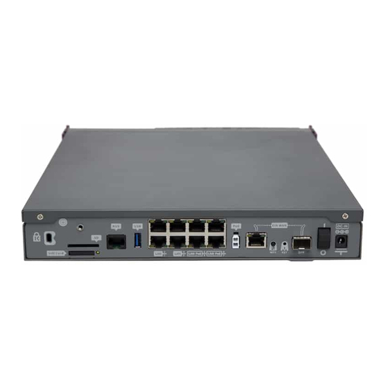
Green -> Link detected. Blinking: con- nection data activity. 3.1.2 Rear Panel The following figure shows the rear panel. Here you will find the majority of the Teldat iM8 router connectors. Rear panel Fig. 3: The following table provides information on each connector, as well as a description:... -
Page 13: Side Panels
SIM Card. Slot where you can insert the SIM card for the external 3G module. SD. Slot where you can insert a SD card. Aux. Provides access to the Teldat iM8 local console for configuring and monitor- ing purposes. USB. Slot where you can insert a 3G USB modem. -
Page 14: Underside Panel
Adhesive rubber feet (these are not required for rack mounting). 3.2 Expansion slot The Teldat iM8 router has an expansion slot. This means you can increase its features and interfaces by inserting different cards or boards. This slot is located on the router's front panel, as shown in the following figure: Expansion slot Fig. -
Page 15: Installation In A Rack
3.3 Installation in a rack The Teldat iM8 device can be installed in a 19” rack. The necessary strips and screws are not provided by default and have to be acquired separately. - Page 16 The central tab that has to be removed Fig. 11: Removable tab part Fig. 12: Breaking off the tab Fig. 13: (2) Both strips are attached to the device by means of 5 screws, as shown in the following figure: Teldat Router iM8...
-
Page 17: Standalone
Fig. 14: 3.3.1 Standalone Teldat iM8 devices can be placed as standalones on a flat, stable surface. The adhesive rubber feet must be stuck to the underside panel to prevent the router from sliding. Make sure there is enough space around the router (for ventilation purposes) and check that the power cord and data cables can reach it. -
Page 18: Uninstall
The Teldat iM8 router is powered through an external AC/DC power adapter. The Teldat iM8 may also incorporate a card to inject PoE through the 4 ports of the 8-port Switch. In this case, an- other external adapter is needed to provide power to PoE module. -
Page 19: Poe Source
• Disconnect the data cables. 3.5.2 PoE Source The Teldat iM8 can be powered through an Ethernet cable that complies with the PoE 802.3af standard (15.4 W per port). Another external adapter and internal card are needed for this functionality. - Page 20 !!!!! ******************************* !!!!! !!!!! ********* DEBUG BIOS ********** !!!!! !!!!! ******** ONLY FOR R&D ********* !!!!! !!!!! ******************************* !!!!! FLASH BIOS CODE VERSION: 01.05 Jan 13 2017 12:28:02 Current date: Feb 23 2011, Wednesday Current time: 10:11:06 Teldat Router iM8...
- Page 21 APP CODE DUMP..................................................................................................APP DATA DUMP............Bios-stack used: 0x4000 Bios-stack free: 0x0 Aux-stack used: 0x11C Aux-stack free: 0x1EE4 Running application at: 0x00200140 License loaded successfully Flash configuration read Parsing text mode configuration ... Teldat Router iM8...
-
Page 22: Rst Button
Note Some devices leave the factory with customized settings. This personalization can mean your router's default configuration is different from the one shown above. 3.7 Connecting the data The Teldat iM8 router has the following data connections. Teldat Router iM8... -
Page 23: 8-Port Ethernet Switch
3.7.2 WAN Connection The Teldat iM8 has 1 Ethernet interface for WAN connection. This port has 2 connectors - SFP for optical link and RJ45 for 10/100/1000 Base-T link - but they cannot work simultaneously. This interface is totally independent from the Switch and is handled as just one more interface. -
Page 24: Wireless Lan Antenna Connection (Wi-Fi Connectors)
3.7.4 Wireless LAN Antenna Connection (Wi-Fi connectors) The Teldat iM8 has four RF antenna connectors for an external antenna to improve the quality of the signal received and transmitted by the Wireless LAN module. These modules are internal and can be activated by purchasing the corresponding software license. To assemble and disassemble the antennas provided with the device, just screw them into the connectors labeled Wi-Fi. -
Page 25: Connecting A 3G Usb Device (Usb Connector)
3.7.5 Connecting a 3G USB device (USB connector) The Teldat iM8 router has a USB HOST 2.0 Type A connector interface. It allows 3G USB modems to be connected. The interface can be activated by purchasing the corresponding software license. - Page 26 The other SIM tray is internal. To access it, you need to access the underside of the router, open the flap (shown in the following figure) and insert the SIM card. Internal module SIM tray Fig. 30: Teldat Router iM8...
-
Page 27: Optional Storage
Fig. 31: 3.9 Optional Storage The applications running in the second core of the device processor can increase the features of the Teldat iM8 router. To access said features, the device must have an internally-installed hard disk or an SD flash memory expansion. - Page 28 (red arrows). Placing the hard disk Fig. 34: (6) Finally, insert the tray into the device once again using the slot guides. Inserting the hard disk Fig. 35: (7) Screw the tray to the device. Teldat Router iM8...
-
Page 29: Procedure To Install A Flash Memory Expansion Sd
3.9.2 Procedure to install a flash memory expansion SD To install an SD card, insert it into the SD tray as shown in the following figure: Inserting SD card Fig. 37: Teldat Router iM8... -
Page 30: Chapter 4 Compliance
4.1 Manufacturer Information Brand Teldat Manufacturer Teldat S.A. Country Spain Postal Address Isaac Newton, 10 Parque Tecnológico de Madrid, 28760 Tres Cantos, Madrid, Spain International Phone +34 91 807 65 65 4.2 Safety Warnings Connecting Discon- necting Teldat Router iM8... - Page 31 4 Compliance Teldat S.A. Teldat Router iM8...
-
Page 32: Weee Information
0.1% weight by weight (w/w). This declaration will be updated whenever- any changes occur or other chemical substances are added to the REACH Candidate List. Information is currently provided to consumers upon request. Teldat Router iM8... -
Page 33: Ec Declaration Of Conformity
In accordance with Article 10 of 2014/53/EU, we inform you that national restrictions and requirements may apply when it comes to authorization. These can evolve with time. Teldat S.A. recommends that you check with local au- thorities what the latest status of national regulations is. -
Page 34: Operating Frequency
To find out more about operating frequencies and the maximum radio-frequency power transmitted in the frequency bands in which the radio equipment operates, see appendix RF WAN specifications on page 38 andWIFI Specifica- tions on page 39. Teldat Router iM8... -
Page 35: Appendix A Technical Information
A.3 Connecting to the device A.3.1 Connecting using the local console (Aux connector) The Teldat iM8 router has a RJ45 female connector on the front panel, known as “ Aux .” , which provides access to the device's local console. -
Page 36: Connectors
RJ45 female-DB9 female adapter (also provided). Connecting for Configuration Fig. 41: A.4 Connectors A.4.1 LAN Connector (Switch) RJ45 LAN RJ45 PIN FE Signals GE Signals BI-DA+ [PoE+] BI-DA+ BI-DA- [PoE+] BI-DA- BI-DB+ [PoE-] BI-DB+ BI-DC+ BI-DC- BI-DB- [PoE-] BI-DB- BI-DD+ BI-DD- Teldat Router iM8... -
Page 37: Wan Base-T Connector
BI-DA+ BI-DA+ BI-DA- BI-DA- BI-DB+ BI-DB+ BI-DC+ BI-DC- BI-DB- BI-DB- BI-DD+ BI-DD- A.4.3 WAN SFP Connector Standard SFP connector A.4.4 WWAN Connector SMA Female Internal RF in/out External A.4.5 WLAN Connector SMA-RP Female Internal RF in/out External Teldat Router iM8... -
Page 38: Usb Connector
RJ45 CONFIGURATION RJ45 PIN CONF A.4.8 Power Supply Connector Jack 5.5/2.5mm Internal -> POSITIVE External -> NEGATIVE A.5 Technical Specifications A.5.1 Hardware Architecture PROCESSORS Freescale QorIQ. MEMORY 1 Gbyte in SDRAM. STORAGE UNIT FLASH Memory (32 Mbytes). Teldat Router iM8... -
Page 39: Lan Interface
SPEED 10/100/1000 Mbps (Base-T). CONNECTOR RJ45 female. A.5.4 WAN SFP Interface STANDARDS 802.1Q (VLAN). 1000-Base-X. SPEED 1000 Mbps full duplex. TYPES LX/LH (single-mode 1310 nm). SX (multi-mode 850 nm). ZX (single-mode 1550 nm). CONNECTOR Standard SFP connector. Teldat Router iM8... -
Page 40: Wireless Wan Interface
• LLTE Cat 3. 100Mbps/50Mbps • HSPA+ Cat 24/6: 42Mbps/5.76Mbps • CDMA 1xRTT: 153Kbps, EV-DO: 3.1Mbps/1.8Mbps • EDGE: 236Kbps CONNECTOR Up to eight type SMA female connectors. SIM Slots 4 Mini-SIM (2FF) ISO/IEC 7810:2003, ID-000 (1.8V / 3V). Teldat Router iM8... -
Page 41: Wireless Lan Interface
Adjustable in dBm. Maximal power varies depending on data rate, frequency band antenna gain) and country setting. Output Power Note: The maximum RF power setting will vary according to specified country regulations. 802.11a: 5.150~5.350 GHz Band: • +16 dBm at 6~24 Mbps • +14 dBm at 48 Mbps Teldat Router iM8... - Page 42 • +13~15dBm at MCS0/8 , 1/9 , 2/10 , 3/11 , 4/12 , 5/13, MCS6/14 • +11~13dBm at MCS7/15 5.470~5.725 GHz Band: • +13~15dBm at MCS0/8 , 1/9 , 2/10 , 3/11 , 4/12 , 5/13, MCS6/14 Teldat Router iM8...
-
Page 43: Usb Interface
40 MHz (bundling two adjoining 20 MHz channels into one 40 MHz channel). A.5.7 USB Interface 3G USB MODEMS Please visit the Teldat website http://www.teldat.com for a list of supported 3G USB modems. SPEED The interface complies with the USB 2.0 (480 Mbps) standard; the end speed de- pends on the 3G USB modem used. -
Page 44: Radio Information
Tx: 1920-1980 MHz +23 dBm ± 1 dB Rx: 2110-2170 MHz Band 3 Tx: 170–1785 MHz +23 dBm ± 1 dB Rx: 1805–1880 MHz Band 8 Tx: 880–915 MHz +23 dBm ± 1 dB Rx: 925–960 MHz Teldat Router iM8... -
Page 45: Wifi Specifications
• Japan: 14 channels. 802.11g/n: • USA: 11 channels. • Europe Countries: 13 channels. • Japan: 13 channels. Output Power. Note: The maximum RF power setting will vary according to country-specific reg- ulations. (tolerance ± 2 dB) 802.11a: Teldat Router iM8... - Page 46 • +14dBm at MCS0/8 , 1/9 , 2/10 , 3/11 , 4/12 , 5/13 • +12dBm at MCS6/14 • +10dBm at MCS7/15 HT40 5.150~5.350 GHz Band: • +13~15dBm at MCS0/8 , 1/9 , 2/10 , 3/11 , 4/12 , 5/13, MCS6/14 Teldat Router iM8...
- Page 47 • +13~15dBm at MCS0/8 , 1/9 , 2/10 , 3/11 , 4/12 , 5/13, MCS6/14 • +10~12dBm at MCS7/15 5.725~5.825 GHz Band: • +12~15dBm at MCS0/8 , 1/9 , 2/10 , 3/11 , 4/12 , 5/13, MCS6/14 • +10~12dBm at MCS7/15 Teldat Router iM8...
Need help?
Do you have a question about the iM8 and is the answer not in the manual?
Questions and answers