
Subscribe to Our Youtube Channel
Related Manuals for Teldat iM8


Summary of Contents for Teldat iM8
- Page 1 Manual Teldat S.A. Teldat Router iM8 Installation Manual Copyright© Teldat-DM649-I Version 1.0 06/2016 Teldat S.A. Teldat Router iM8...
- Page 2 This publication is subject to change. Teldat S.A. offers no warranty whatsoever for information contained in this manual. Teldat S.A. is not liable for any direct, indirect, collateral, consequential or any other damage connected to the deliv- ery, supply or use of this manual.
-
Page 3: Table Of Contents
Teldat- iM8 ........4... - Page 4 WAN SFP Interface ........A.5.5 Wireless WAN Interface ....... . Teldat Router iM8...
- Page 5 Dimensions and weight ....... . A.5.11 Environmental Specifications ......Teldat Router iM8...
- Page 6 Table of Contents Teldat S.A. Teldat Router iM8...
-
Page 7: I Related Documents
Related Documents Teldat S.A. I Related Documents Teldat-DM748-I Software Updating Teldat Router iM8... -
Page 8: Chapter 1 About This Guide
1 About This Guide Teldat S.A. Chapter 1 About This Guide This installation guide for the Teldat- iM8router contains information on how to correctly install this device in a work- ing environment. 1.1 Supported Devices The information provided in this installation guide only applies to the Teldat-iM8 router. - Page 9 1 About This Guide Teldat S.A. Fax: +34 918 076 566 Email: support@teldat.com Teldat Router iM8...
-
Page 10: Teldat Im8
2.1.2 Hardware Monitoring The Teldat-iM8 router hardware is monitored through the LEDs located on the front panel. Said LEDs provide visual information on the state of the device and reference the condition of the hardware components, if there is connectiv- ity, data flow, etc. -
Page 11: Chapter 3 Components And Power Supply
3 Components and Power Supply Teldat S.A. Chapter 3 Components and Power Supply The following chapter provides detailed information on the chassis of the Teldat-iM8 router and its components. This information includes: • Components. • Information on assembly. • Installing and uninstalling modules. - Page 12 LAN Switch Tricolor Green -> connected. Blink- ing: connection data activ- ity. Red -> disconnected. Off -> interface off. Eth WAN Base-t Tricolor Green -> connected. Blink- ing: connection data activ- ity. Off -> not used. Teldat Router iM8...
- Page 13 Red -> Error. Apps Tricolor Off -> no applications de- tected. Green -> applications de- tected. Amber -> testing applica- tion. Red -> application error. Slot Tricolor Off -> There is no card in the expansion slot. Teldat Router iM8...
-
Page 14: Rear Panel
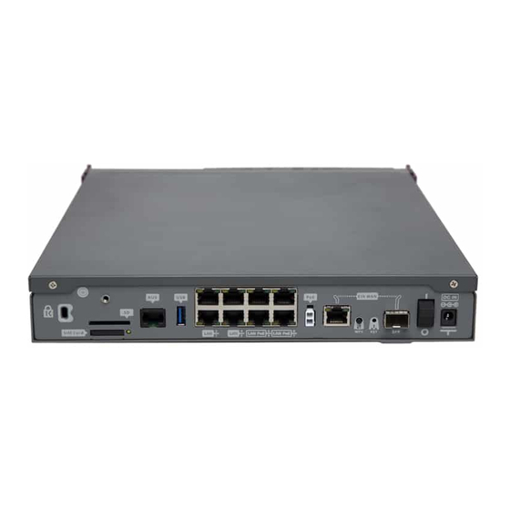
Green -> Link detected. Blinking: con- nection data activity. 3.1.2 Rear Panel The following figure shows the rear panel. Here you will find the majority of the Teldat-iM8 router connectors. Rear panel Fig. 3: The following table provides information on each connector as well as a description:... -
Page 15: Side Panels
Four WiFi antenna and two 3G antenna connectors are located on the side panels. Left and right side panels Fig. 4: The connectors are as follows: Side panel connectors Item Description WiFi Antenna connectors. 3G Antenna connectors. 3.1.4 Underside Panel The following elements are located on the underside panel: Teldat Router iM8... -
Page 16: Expansion Slot
Adhesive rubber feet (these are not required if mounted in a rack). 3.2 Expansion Slot The Teldat-iM8 router has an expansion slot. This means you may increase its features and interfaces by inserting different cards or boards. This slot is located on the router front panel, as shown in following figure: Expansion slot Fig. - Page 17 Remember to attach the card using the appropriate screws and try not to damage it during the tightening process. Placing the expansion card Fig. 9: (6) Finally, put the tray that holds the card back into the device. Teldat Router iM8...
-
Page 18: Installation In A Rack
(8) Connect a terminal to the console and check the device has detected the expansion card. 3.3 Installation in a rack The Teldat-iM8 device can be installed in a 19” rack. The necessary strips and screws are not provided by default and have to be acquired separately. -
Page 19: Standalone
Fig. 15: 3.3.1 Standalone The Teldat-iM8 can be placed as a standalone on a flat, stable surface. The adhesive rubber feet must be stuck to the underside panel to prevent the router from sliding. Make sure there is enough space around the router (for ventilation purposes) and check the electricity cables can reach it. -
Page 20: Installation
The Teldat-iM8 is powered though an external AC/DC source. Additionally, the Teldat-iM8 incorporates a card to inject PoE through the 4 ports of the 8-port Switch. In this case, the device must be connected to an AC/DC external power source to power said module. -
Page 21: Poe Source
• Disconnect the data cables. 3.5.2 PoE Source The Teldat-iM8 can be powered through an Ethernet cable that complies with the PoE 802.3af standard (15.4 W per port). The following figure shows how to connect the PoE source to the device: PoE source connection and PoE ports Fig. -
Page 22: Default Configuration
The Teldat-iM8 is equipped with the following data connections. 3.7.1 8-port Ethernet Switch The Teldat-iM8 incorporates a 8-port 10/100/1000 BaseT Switch with automatic MDI/MDIX to connect to a local area network (LAN). Please pay careful attention to the labeling so you do not confuse this switch with other types of ports: LAN switch PORTs Fig. -
Page 23: Wwan Antenna Connection (Cell Connector)
The Teldat-iM8 has two connectors for 3G antennas. To assemble and disassemble the antennas, simply screw them into the connectors labeled Cell (located on the right panel of the router). Installing these antennas in the Teldat-iM8 is essential to improve the quality of the signal received and transmitted by the cellular model. -
Page 24: Wireless Lan Antenna Connection (Wi-Fi Connectors)
3.7.4 Wireless LAN Antenna Connection (Wi-Fi connectors) The Teldat-iM8 has four RF antenna connectors for an external antenna, in order to improve the quality of the signal received and transmitted by the Wireless LAN module. Theses modules are internal and can be activated by purchasing the corresponding software license. To assemble and disassemble the antennas provided with the device, just screw them into the connectors, labeled Wi-Fi, which are located on the rear and on both lateral panels of the router. -
Page 25: Installing The Sim Card
3.8 Installing the SIM card The Teldat-iM8 is equipped with a Wireless WAN interface that may need a SIM card to be inserted in order to oper- ate. Certain services (CDMA) provided by several carriers in some countries do not require SIM cards. - Page 26 (2) Open the upper part of the tray. (3) Fully insert the SIM card using the slot guides. (4) Return the tray to its original position. (5) While pressing the tray, push the fastening towards the word LOCK until it is firmly in place. Teldat Router iM8...
-
Page 27: Optional Storage
Fig. 28: 3.9 Optional Storage Features in the Teldat-iM8 router can be increased through the applications it has stored in the second core of the device processor. To access said features, the device must have an internally-installed hard disk or a SD flash memory expansion. - Page 28 Then fix the hard disk using the appropriate screws without damage it during the tightening process. Placing the hard disk Fig. 31: (6) Finally, insert the tray into the device once again using the slot guides. Inserting the hard disk Fig. 32: (7) Screw the tray to the device. Teldat Router iM8...
-
Page 29: Procedure To Install A Flash Memory Expansion Sd
(8) Connect a terminal to the console and make sure the device detects the hard disk. 3.9.2 Procedure to install a flash memory expansion SD To install an SD, insert the SD card into the SD tray as shown in the following figure: Inserting SD card Fig. 34: Teldat Router iM8... -
Page 30: Chapter 4 Compliance
Teldat S.A. Chapter 4 Compliance 4.1 Manufacturer Information Teldat Brand Manufacturer Teldat S. A. Country Spain Postal Address Isaac Newton, 10 Parque Tecnológico de Madrid, 28760 Tres Cantos, Madrid, Spain International Phone +34 91 807 65 65 Teldat Router iM8... -
Page 31: Safety Warnings
4 Compliance Teldat S.A. 4.2 Safety Warnings Connecting Discon- necting Teldat Router iM8... -
Page 32: Weee Information
0.1% weight by weight (w/w). This declaration will be updated whenever- any changes occur or other chemical substances are added to the REACH Candidate List. Information is cur- rentlyprovided to consumers upon request. Teldat Router iM8... -
Page 33: Ec Declaration Of Conformity
In accordance with Article 10 of 2014/53/EU, we inform you that national restrictions and requirements may apply when it comes to authorization. These can evolve with time. Teldat S.A. recommends that you check with local au- thorities what the latest status of national regulations is. -
Page 34: Appendix A Technical Information
A.3 Connecting to the device A.3.1 Connecting using the local console (Aux connector) The Teldat-iM8 router has a RJ45 female connector on the front panel (known as “ Aux .”) that provides access to the device local console. Teldat Router iM8... -
Page 35: Connectors
RJ45 female-DB9 female adapter (also provided). Connecting for Configuration Fig. 38: A.4 Connectors A.4.1 LAN Connector RJ45 LAN RJ45 PIN FE Signals GE Signals BI-DA+ BI-DA+ BI-DA- BI-DA- BI-DB+ BI-DB+ BI-DC+ BI-DC- BI-DB- BI-DB- BI-DD+ BI-DD- Teldat Router iM8... -
Page 36: Wan Base-T Connector
BI-DA+ BI-DA- BI-DA- BI-DB+ BI-DB+ BI-DC+ BI-DC- BI-DB- BI-DB- BI-DD+ BI-DD- A.4.3 WAN SFP Connector RJ45 WAN RJ45 PIN Signal RING A.4.4 WWAN Connector (female) Internal RF in/out External A.4.5 WLAN Connector (male) Internal RF in/out External Teldat Router iM8... -
Page 37: Usb Connector
Shield A.4.7 Configuration Connector RJ45 CONFIGURATION RJ45 PIN CONF A.4.8 Power Supply Connector Internal POSITIVE External NEGATIVE A.5 Technical Specifications A.5.1 Hardware Architecture PROCESSORS Freescale QorIQ MEMORY 1 Gbyte in SDRAM STORAGE UNIT FLASH Memory (32 Mbytes). Teldat Router iM8... -
Page 38: Lan Interface
Depends on the type of wireless WAN module installed. Please refer to the an- tenna catalog for cellular interfaces. A.5.6 Wireless LAN Interface STANDARDS 802.11abgn FREQUENCY 2.4 GHz / 5 GHz SPEED Depends on the Wireless LAN module. CONECTOR Up to 4 RF RP-SMA female. Teldat Router iM8... -
Page 39: A.5.7 Usb Interface
Technical Information Teldat S.A. A.5.7 USB Interface 3G USB MODEMS Please visit the Teldat website http://www.teldat.com to get a list of the supported 3G USB modems. SPEED The interface complies with the USB 2.0 (480 Mbps) standard; the end speed de- pends on the 3G USB modem used.
Need help?
Do you have a question about the iM8 and is the answer not in the manual?
Questions and answers