cytiva AKTA readyflux Operating Instructions Manual
Hide thumbs
Also See for AKTA readyflux:
- Operating instructions manual (202 pages) ,
- Unpacking instructions manual (32 pages)
Table of Contents
Advertisement
Quick Links
Advertisement
Table of Contents

Related Manuals for cytiva AKTA readyflux


Summary of Contents for cytiva AKTA readyflux
- Page 1 ÄKTA readyflux™ Operating Instructions Original instructions cytiva.com...
-
Page 2: Table Of Contents
Table of Contents Table of Contents Introduction ......................5 Important user information ........................6 About this manual ............................7 Associated documentation ........................8 Abbreviations ..............................10 Safety instructions ..................... 11 Safety precautions ............................12 Labels and symbols ............................16 Emergency procedures ..........................18 System description .................... - Page 3 Table of Contents Power supply ..............................108 Install the pump upgrade kit ........................112 Operation ......................118 Safety precautions ............................119 Flow kit installation ............................124 5.2.1 Preparations ..............................126 5.2.2 Flow kit package ............................127 5.2.3 Install the CFF flow kit ..........................128 5.2.4 Install the NFF flow kit ..........................
- Page 4 Table of Contents 8.6.8 Declaration of Hazardous Substances (DoHS) ................249 Health and Safety Declaration Form ...................... 253 More information ............................255 Index ........................... 256 ÄKTA readyflux Operating Instructions 29175550 AG...
-
Page 5: Introduction
1 Introduction Introduction About this chapter This chapter contains information about this manual and associated user documenta- tion, important user information and intended use of the ÄKTA readyflux™ system. In this chapter Section See page Important user information About this manual Associated documentation Abbreviations ÄKTA readyflux Operating Instructions 29175550 AG... -
Page 6: Important User Information
1 Introduction 1.1 Important user information Important user information Introduction This section contains important user information about the product and this manual. Read this before operating the product All users must read the entire Operating Instructions before installing, oper- ating, or maintaining the product. Always keep the Operating Instructions at hand when operating the product. -
Page 7: About This Manual
1 Introduction 1.2 About this manual About this manual Purpose of this manual The Operating Instructions provide the information needed to install, operate and maintain the product in a safe way. Scope of this manual The Operating Instructions manual covers the ÄKTA readyflux system including the optional Bagkart™... -
Page 8: Associated Documentation
Introduction This section describes the user documentation that is delivered with the product, and how to find related literature that can be downloaded or ordered from Cytiva. User documentation The user documentation listed in the table below is available in printed, PDF, or elec- tronic Help format. - Page 9 ÄKTA readyflux also includes product documentation binders containing detailed specifications and traceability documents. Component documentation Documentation for components produced both by Cytiva and by a third-party are, if existent, also included in the product documentation. ÄKTA readyflux Operating Instructions 29175550 AG...
-
Page 10: Abbreviations
1 Introduction 1.4 Abbreviations Abbreviations Introduction This section explains abbreviations that appear in the user documentation for ÄKTA readyflux. Abbreviations Abbrevia- Definition (English) Translation tion Cross flow filtration Cross flow filtration Good Manufacturing Practice Good Manufacturing Practice Hollow fiber Hollow fiber Instrument configuration Instrument configuration Liter per minute... -
Page 11: Safety Instructions
2 Safety instructions Safety instructions About this chapter This chapter describes safety precautions, labels and symbols that are attached to the equipment. In addition, the chapter describes emergency and recovery procedures. In this chapter Section See page Safety precautions Labels and symbols Emergency procedures ÄKTA readyflux Operating Instructions 29175550 AG... -
Page 12: Safety Precautions
2 Safety instructions 2.1 Safety precautions Safety precautions Introduction ÄKTA readyflux is powered by mains voltage and handles materials that may be hazardous. Before installing, operating or maintaining the system, the user must be aware of the hazards described in this manual. Definitions This user documentation contains safety notices (WARNING, CAUTION, and NOTICE) concerning the safe use of the product. - Page 13 WARNING Electrical shock hazard. All installation, service and maintenance of components inside the electrical cabinet must be done by personnel authorized by Cytiva. WARNING Accessories. Use only accessories supplied or recommended by Cytiva. ÄKTA readyflux Operating Instructions 29175550 AG...
- Page 14 2 Safety instructions 2.1 Safety precautions WARNING Do not use the product if it is not working properly, or if it has suffered any damage including: • damage to the power cord or its plug, • damage caused by dropping the product, •...
- Page 15 2 Safety instructions 2.1 Safety precautions Flammable liquids and explosive environment WARNING Flammable liquids. This product is not approved for handling liquids under conditions when they can be flammable. WARNING Explosion hazard: The product is not approved for use in a potentially explosive atmosphere.
-
Page 16: Labels And Symbols
2 Safety instructions 2.2 Labels and symbols Labels and symbols Introduction This section describes the system label and other safety or regulatory labels that are attached to the product. Nameplate The system nameplate is located on the back of the equipment. The nameplate identi- fies the equipment and shows electrical data, regulatory compliance, and warning symbols. - Page 17 2 Safety instructions 2.2 Labels and symbols Symbol/text Description Warning! Hazardous Voltage. Always make sure that the system is disconnected from electric power before opening the cabinet doors or disconnecting any electric device. Warning! Pinch hazard. This sign is located next to pinch valves.
-
Page 18: Emergency Procedures
2 Safety instructions 2.3 Emergency procedures Emergency procedures Introduction This section describes how to do an emergency shutdown of the ÄKTA readyflux system, and the procedure for restarting the system. The section also describes the result in the event of power failure. Precautions WARNING Pressurized flow path. - Page 19 2 Safety instructions 2.3 Emergency procedures Emergency shutdown In an emergency situation, follow the steps below to stop the run: Intended action Procedure Stop the run • Press the EMERGENCY STOP button. • To stop the run from UNICORN, click the End button in the System Control module.
- Page 20 2 Safety instructions 2.3 Emergency procedures Power failure of unit Result Computer • The UNICORN computer shuts down. • The Power/Communication indicator (white) on the Instrument control panel displays a slowly flashing light. • The run is interrupted immediately. • Data generated up to 10 seconds before the power failure can be recovered.
-
Page 21: System Description
3 System description System description About this chapter This chapter provides an overview of the technical properties of ÄKTA readyflux. In this chapter Section See page System overview Illustrations Components Flow path Filters UNICORN control system ÄKTA readyflux Operating Instructions 29175550 AG... -
Page 22: System Overview
3 System description 3.1 System overview System overview Introduction ÄKTA readyflux is a single-use system for cross flow filtration (CFF) and normal flow filtration (NFF). It is intended for use in development and GMP production processes of pharmaceuticals. The ÄKTA readyflux system is primarily used for the production of MAbs, but can also be used for vaccines and recombinant proteins. - Page 23 3 System description 3.1 System overview ÄKTA readyflux is designed for downstream operations as well as upstream harvesting in line with cGMP guidelines. Other applications are cell harvesting, cell or lysate clarifi- cation, product concentration, normal flow filtration and diafiltration. The system can be used with both hollow fiber filter cartridges and flat sheet membrane cassettes.
-
Page 24: Illustrations
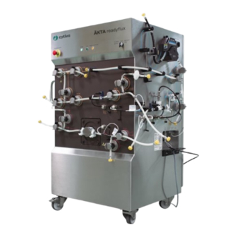
3 System description 3.2 Illustrations Illustrations Introduction This section provides illustrations of the ÄKTA readyflux system. The main features and components are indicated. ÄKTA readyflux overview The illustration below shows the ÄKTA readyflux system. Part Function Cabinet transfer side Cabinet permeate side Top panel Front panel Swivel casters with brake... - Page 25 3 System description 3.2 Illustrations ÄKTA readyflux top panel The illustration below shows the top panel of the ÄKTA readyflux system. Part Function EMERGENCY STOP button POWER, RUN, and PAUSE/CONTINUE indicator lights FLOW KIT INSTALL - RUN - INTEGRITY TEST selector switch CAUTION The PAUSE/CONTINUE button on the system will toggle between pause and run.
- Page 26 3 System description 3.2 Illustrations ÄKTA readyflux front panel The illustration below shows the front panel of the ÄKTA readyflux system. Part Function Transfer valve XV-084 Recirculation valve from permeate XV-085 Transfer to retentate valve XV-086 Pressure control valve PCV-341 Retentate valve to bag XV-052 Feed/buffer inlet valve XV-004 Feed inlet valve from bag XV-005...
- Page 27 3 System description 3.2 Illustrations ÄKTA readyflux cabinet permeate side The illustration below shows the permeate side of the ÄKTA readyflux system. Part Function UV sensor AE-131 Position for mounting bracket for hollow fiber cartridges, see Section 3.5.2 Hollow fiber filters, on page Clamp for pH sensor cable Tube supports Connector for pressure sensor PT-113...
- Page 28 3 System description 3.2 Illustrations Part Function Permeate pump P-203 Inlet valve XV-034 for permeate pump and UV sensor Permeate recirculation inlet valve XV-033 Permeate outlet valve XV-032 Permeate drain valve XV-031 External connectors, see External connectors on page 30 ÄKTA readyflux Operating Instructions 29175550 AG...
- Page 29 3 System description 3.2 Illustrations ÄKTA readyflux cabinet transfer side The illustration below shows the transfer side of the ÄKTA readyflux system. Part Function Air filter clamp Air inlet valve XV-081 Air sensor AE-151 Buffer inlet valve XV-082 Product/Fed batch process inlet valve XV-083 Push handle External connectors, see External connectors on page 30...
- Page 30 3 System description 3.2 Illustrations External connectors The illustrations below show the ports for external connectors on ÄKTA readyflux. Ports on the permeate side: Part Function POWER SUPPLY System power supply connector PNEUMATIC AIR Pneumatic air supply SUPPLY CUSTOMER I/O - 1 I/O socket, see Section 3.3.4 CUSTOMER I/O connec- tors, on page 45...
- Page 31 3 System description 3.2 Illustrations Ports on the transfer side: Part Function PROFIBUS OUT PROFIBUS connector out PROFIBUS IN PROFIBUS connector in WE 176 Weight scale connector CUSTOMER I/O - 2 I/O socket, see Section 3.3.4 CUSTOMER I/O connec- tors, on page 45 ÄKTA readyflux Operating Instructions 29175550 AG...
- Page 32 3 System description 3.2 Illustrations Bagkart The illustration below shows the Bagkart trolley. Part Function Load cell Cable from load cell to instrument Push handle Storage cabinet Swivel casters with brake Bag holder Dummy connector for load cell ÄKTA readyflux Operating Instructions 29175550 AG...
- Page 33 3 System description 3.2 Illustrations Fluxkart The illustration below shows the Fluxkart trolley. Part Function Push handle Spillage collector Swivel casters with brake ÄKTA readyflux Operating Instructions 29175550 AG...
-
Page 34: Components
3 System description 3.3 Components Components About this section This section provides an overview of the different components of ÄKTA readyflux. In this section Section See page 3.3.1 Flow kits 3.3.2 Pumps and valves 3.3.3 Meters and sensors CUSTOMER I/O connectors 3.3.4 ÄKTA readyflux Operating Instructions 29175550 AG... -
Page 35: Flow Kits
3 System description 3.3 Components 3.3.1 Flow kits 3.3.1 Flow kits Introduction ÄKTA readyflux flow kits consist of tubing, sensors, a pump chamber, and fittings. The flow kits, including pump chamber and sensors, are disposable. This section describes the flow path of the flow kits available for ÄKTA readyflux: •... - Page 36 3 System description 3.3 Components 3.3.1 Flow kits Color Function Description Blue Permeate and recirculation flow path Flow path that handles process fluid that passed through the filter. Yellow Retentate and transfer flow path Flow path returning from the filter to the feed source.
- Page 37 14 days from the initial wetting of the flow kit. After 48 hours of operational use or 14 days after initial wetting of the flow kit, the kit must be discarded. For more details regarding flow kit durability, contact your Cytiva representative.
-
Page 38: Pumps And Valves
3 System description 3.3 Components 3.3.2 Pumps and valves 3.3.2 Pumps and valves Introduction This section describes the components located on the panels of the ÄKTA readyflux system: • Front panel • Transfer side panel • Permeate side panel The designations of the components are shown in the flow chart in Section 3.4.1 Flow- chart and description for CFF, on page Pumps... - Page 39 3 System description 3.3 Components 3.3.2 Pumps and valves Feed pump The feed pump P-201 installed on ÄKTA readyflux is a four piston diaphragm pump. It uses a single-use pump chamber that is part of the flow kit and that is disposed of after usage.
- Page 40 3 System description 3.3 Components 3.3.2 Pumps and valves Transfer and permeate pumps The transfer (P-202) and permeate (P-203) pump installed on ÄKTA readyflux are peri- staltic pumps. Peristaltic pumps can run dry. The occlusion settings knob on the transfer pump and the permeate pump is by default set to 2.
- Page 41 3 System description 3.3 Components 3.3.2 Pumps and valves Pinch valves Pinch valves are used to control the path of the liquid flow through the flowpath. There are 20 pinch valves and one PCV. The valves have manually operated safety locks keeping the tubing in place and preventing the valves from accidentally closing during flow kit installation.
- Page 42 3 System description 3.3 Components 3.3.2 Pumps and valves Valves Default position Feed flow path valves, XV-004 and XV-071 Closed Feed flow path valves, XV-005 and XV-006 Open Note: Valves are either open or closed, except for the PCV valve which can be closed gradually.
-
Page 43: Meters And Sensors
3 System description 3.3 Components 3.3.3 Meters and sensors 3.3.3 Meters and sensors Introduction Sensors that measure pressure, conductivity, temperature, pH, flow and UV are included in the ÄKTA readyflux flow kits. The sensors are disposable and intended for single use only. They are pre-calibrated. The sensors are connected to meter units inside the instrument cabinet. - Page 44 3 System description 3.3 Components 3.3.3 Meters and sensors Sensor Location Conductivity sensor CE-102 and Permeate flow path temperature sensor TE-162 The locations of the conductivity and temperature sensors are also depicted in Flow- chart on page Conductivity measurement is temperature compensated and thus dependent on correct temperature readings.
-
Page 45: Customer I/O Connectors
3 System description 3.3 Components 3.3.4 CUSTOMER I/O connectors 3.3.4 CUSTOMER I/O connectors Introduction The CUSTOMER I/O connectors are 9-pole (CUSTOMER I/O - 1) and 15-pole (CUSTOMER I/O - 2) IP67-proof D-sub pin connectors. Matching socket connectors containing a screw terminal block with watertight housing are supplied with the system. - Page 46 3 System description 3.3 Components 3.3.4 CUSTOMER I/O connectors CUSTOMER I/O - 2 The table below provides a list of the ports of the CUSTOMER I/O - 2 connector at the transfer side of the ÄKTA readyflux system. Definition of signal +24V Digital output, Remote alarm Free +ve 4-20 mA, WE-177...
-
Page 47: 3.4 Flow Path
3 System description 3.4 Flow path Flow path Introduction This section describes the flow path when using CFF or NFF flow kits with the system. In this section Section See page 3.4.1 Flowchart and description for CFF 3.4.2 Flowchart and description for NFF ÄKTA readyflux Operating Instructions 29175550 AG... -
Page 48: Flowchart And Description For Cff
3 System description 3.4 Flow path 3.4.1 Flowchart and description for CFF 3.4.1 Flowchart and description for CFF Introduction This section shows the flowchart and describes the flow path of CFF flow kits. Flowchart The illustration below shows the flowchart for CFF flow kits. FA 231 XV 081 FA 232... - Page 49 3 System description 3.4 Flow path 3.4.1 Flowchart and description for CFF Symbol Function Filter Sensor Connector Air filter Load cell Accessory Customer I/O Air sensor Conductivity sensor Flow sensor Pump pH sensor Feed pressure sensor Permeate pressure sensor Retentate pressure sensor Temperature sensor Ultra Violet sensor Weight...
- Page 50 3 System description 3.4 Flow path 3.4.1 Flowchart and description for CFF The feed flow path can be cut off with the XV-006 valve and drained through the XV-071 valve. The air sensor AE-152 can be placed on the tubing between XV-003 and XV-004 to continuously monitor air bubbles in the flow path.
- Page 51 3 System description 3.4 Flow path 3.4.1 Flowchart and description for CFF Maximum pressures The pressure is monitored by three pressure sensors, see Pressure sensors on page The different pressure levels are illustrated with dashed lines in the flow chart below. FA 231 XV 081 FA 232...
-
Page 52: Flowchart And Description For Nff
3 System description 3.4 Flow path 3.4.2 Flowchart and description for NFF 3.4.2 Flowchart and description for NFF Introduction This section shows the flowchart and describes the flow path of the NFF flow kit. Flowchart The illustration below shows the flowchart for the NFF flow kit. XV 004 PT 113 FE 141... - Page 53 3 System description 3.4 Flow path 3.4.2 Flowchart and description for NFF Symbol Function Sensor Connector Load cell Accessory Customer I/O Air sensor Flow sensor Pump Feed pressure sensor Permeate pressure sensor Temperature sensor Weight Feed flow path description The purpose of the feed flow path (red line in the flow chart) is to transfer the feed from the feed source (2D or 3D bag) via the pump to the filter.
-
Page 54: Filters
3 System description 3.5 Filters Filters About this section This section provides an overview of the different filter types that can be used with ÄKTA readyflux. In this section Section See page 3.5.1 Flat sheet filters 3.5.2 Hollow fiber filters ÄKTA readyflux Operating Instructions 29175550 AG... -
Page 55: Flat Sheet Filters
3 System description 3.5 Filters 3.5.1 Flat sheet filters 3.5.1 Flat sheet filters Introduction The ÄKTA readyflux Fluxkart provides a convenient way to position the filter holder at the correct height to match the length of the flow kit tubing. For more information about cassette models and sizes, see Membrane filter cassette specifications, on page... -
Page 56: Hollow Fiber Filters
3 System description 3.5 Filters 3.5.2 Hollow fiber filters 3.5.2 Hollow fiber filters Introduction ÄKTA readyflux is designed to operate with hollow fiber cartridges of different sizes. These cartridges are described in the Selection Handbook Hollow fiber cartridges and systems for membrane separations. For more information on cartridge models and sizes, see Hollow fiber cartridge specifi- cations on page... - Page 57 3 System description 3.5 Filters 3.5.2 Hollow fiber filters Mounting brackets for hollow fiber cartridges The mounting brackets for hollow fiber cartridges are located on the permeate side of the ÄKTA readyflux system. The mounting brackets have a hinged arm where the hollow fiber cartridge is inserted. The hinged arm is secured with a knurled nut.
-
Page 58: Unicorn Control System
3 System description 3.6 UNICORN control system UNICORN control system About this section This section provides an overview of the UNICORN software that is used to operate the ÄKTA readyflux system. In this section Section See page 3.6.1 Introduction 3.6.2 Description of UNICORN 3.6.3 The System Control module... -
Page 59: Introduction
UNICORN is compatible with FDA 21 CFR Part 11. Documentation The UNICORN software phases and the UNICORN user documentation provide complete instructions for programming and for using the software for process control. Contact your local Cytiva representative for advice if required. ÄKTA readyflux Operating Instructions 29175550 AG... -
Page 60: Description Of Unicorn
3 System description 3.6 UNICORN control system 3.6.2 Description of UNICORN 3.6.2 Description of UNICORN Software modules The UNICORN control software consists of four modules: Module Function Administration File handling and administration tasks; for example, definition of systems and managing user profiles. -
Page 61: The System Control Module
3 System description 3.6 UNICORN control system 3.6.3 The System Control module 3.6.3 The System Control module Introduction The System Control module is used to start, view, and control a manual or method run. System Control toolbar buttons The following table shows the System Control toolbar buttons that are referred to in this manual. - Page 62 3 System description 3.6 UNICORN control system 3.6.3 The System Control module ÄKTA readyflux Operating Instructions 29175550 AG...
-
Page 63: Process Picture
3 System description 3.6 UNICORN control system 3.6.4 Process picture 3.6.4 Process picture Introduction The process picture is a schematic representation of the system and is shown in the Process Picture pane in the System Control module. The process picture displays the current flow path and system parameters during a run and can be used to control the run. - Page 64 3 System description 3.6 UNICORN control system 3.6.4 Process picture Symbol Description Filter Flow path Pressure control valve Active pump (green rotating triangle) Inactive pump (gray triangle) Sensor Open valve Closed valve ÄKTA readyflux Operating Instructions 29175550 AG...
- Page 65 3 System description 3.6 UNICORN control system 3.6.4 Process picture The Idle state When the system is powered on, and all the components are initialized to their default states, the process picture shows the Idle (ready) state of the system. The system state panel says Idle and the different flow paths are illustrated in the colors red, yellow, and blue, as shown in the illustration below.
- Page 66 3 System description 3.6 UNICORN control system 3.6.4 Process picture The illustration below shows the Running state for the NFF flow kit. Color Indication Green Open flow path Gray Closed flow path Note: The optional components are shown in the process picture based on the user selection of components in the Administration module of UNICORN.
- Page 67 3 System description 3.6 UNICORN control system 3.6.4 Process picture The table below describes the settings. Settings Description Units Select the units for flow and pressure in the process picture. The available options are: Flow: L/h or L/min or % Pressure: bar or psi Choose the preferred settings and click OK.
- Page 68 3 System description 3.6 UNICORN control system 3.6.4 Process picture Settings Description Set the values for the pressure control valve. Enter the preferred values and click OK. ÄKTA readyflux Operating Instructions 29175550 AG...
- Page 69 3 System description 3.6 UNICORN control system 3.6.4 Process picture Settings Description Automated- Set the values for the automated values such as TMP, Values DeltaP, CFP, Flux, Shear, and CRV. Enter the preferred values and click OK. Note: When operating in Flux mode, the permeate flow rate can only be set in steps of 0.01 L/min.
- Page 70 3 System description 3.6 UNICORN control system 3.6.4 Process picture The Settings panel for NFF Different settings can be changed from the Settings panel. The illustration below shows the Settings panel for the NFF flow kit. The table below describes the settings. Settings Description Units...
- Page 71 3 System description 3.6 UNICORN control system 3.6.4 Process picture Settings Description Inactive when running the NFF flow kit. Automated- Set the values for the automated values such as DeltaP and Values CFP. Enter the preferred values and click OK. ÄKTA readyflux Operating Instructions 29175550 AG...
- Page 72 3 System description 3.6 UNICORN control system 3.6.4 Process picture Settings Description DisplayParame- Show or hide all the labels in the process picture. ters Select the Show/Hide Labels check box to show the labels. Pumps WARNING Make sure that a valid flow path exists before running a pump manually.
- Page 73 3 System description 3.6 UNICORN control system 3.6.4 Process picture To change the values of a pump there are two options: • Click on the value on the pump symbol in the process picture. Result: The Settings panel opens. • Click Pumps in the Settings panel. The flow can be set using the following three units: L/h or L/min or %.
- Page 74 3 System description 3.6 UNICORN control system 3.6.4 Process picture ÄKTA readyflux Operating Instructions 29175550 AG...
-
Page 75: Warnings And Alarms
3 System description 3.6 UNICORN control system 3.6.5 Warnings and alarms 3.6.5 Warnings and alarms Warnings Warnings are generated to warn operating personnel that process parameters have exceeded preset high and/or low limits. The process method continues after the warning has been acknowledged. Alarm signals If equipment is connected that has lower limits than the system, the alarm levels must be set accordingly. -
Page 76: Installation
4 Installation Installation About this chapter This chapter provides required information to enable users and service personnel to transport, unpack and install the product. In this chapter Section See page Safety precautions Site preparation Transport Unpack the system Setup Power supply Install the pump upgrade kit ÄKTA readyflux Operating Instructions 29175550 AG... -
Page 77: Safety Precautions
4 Installation 4.1 Safety precautions Safety precautions Power supply WARNING Supply voltage. Before connecting the power cord, make sure that the supply voltage at the wall outlet corresponds to the requirements for the instrument. WARNING Protective ground. The product must be connected to a grounded power outlet. - Page 78 4 Installation 4.1 Safety precautions Installing and moving the system WARNING The product must be installed and prepared by Cytiva personnel or a third party authorized by Cytiva. WARNING Move transport crates. Make sure that the lifting equipment has the capacity to safely lift the crate weight. Make sure that the crate is properly balanced so that it will not accidentally tip when moved.
- Page 79 4 Installation 4.1 Safety precautions CAUTION The product is designed for indoor use only. CAUTION Do not use the product in a dusty atmosphere or close to spraying water. CAUTION Packing crates may have been exposed to pesticides, depending on the regulations of the country of delivery. Recycle packing crates according to local recommendations for pesticide-treated wood.
- Page 80 4 Installation 4.1 Safety precautions CAUTION The maximum weight of the 2D Bag on the Bagkart is 25 kg. Bagkart must only be tared with an empty bag and empty flow kits. Incorrect taring will result in overload of the Bagkart trolley or the bag, which may result in bag burst.
-
Page 81: Site Preparation
4 Installation 4.2 Site preparation Site preparation Introduction This section describes the site planning and preparation that should be performed before the product is installed. See also the ÄKTA readyflux Site Preparation Guide. In this section Section See page 4.2.1 Room requirements 4.2.2 Site environmental requirements... -
Page 82: Room Requirements
4 Installation 4.2 Site preparation 4.2.1 Room requirements 4.2.1 Room requirements Introduction This section describes the requirements for the room where the instrument is placed. Dimensions The dimensions of the ÄKTA readyflux system shown in the illustration below are 275 cm × 88 cm × 155 cm (width × depth × height). The following table lists the dimensions of the individual products in the ÄKTA readyflux system. - Page 83 4 Installation 4.2 Site preparation 4.2.1 Room requirements Weight The following table lists the weights of the individual products in the ÄKTA readyflux system. Product Weight (kg) ÄKTA readyflux instrument Bagkart Fluxkart Space requirements For space and floor requirement, see external dimensions and weights in Dimensions, on page •...
-
Page 84: Site Environmental Requirements
4 Installation 4.2 Site preparation 4.2.2 Site environmental requirements 4.2.2 Site environmental requirements Introduction This sections describes the environmental requirements and conditions for installa- tion of ÄKTA readyflux. Environmental requirements The installation site must comply with the following specifications: Parameter Specification Allowed location Indoor use only... -
Page 85: Electrical Power Requirements
4 Installation 4.2 Site preparation 4.2.3 Electrical power requirements 4.2.3 Electrical power requirements Parameter Specification Supply voltage 100 to 240 V AC ± 10% Frequency 50/60 Hz Max. power consumption 1 kVA Circuit breaker 16 A WARNING Protective ground. The system must be connected to a grounded power outlet. -
Page 86: Media Supply
4 Installation 4.2 Site preparation 4.2.4 Media supply 4.2.4 Media supply Supply must be arranged so that piping dimensions, piping lengths, valves and height differences do not obstruct processing. Section 8.1 Specifications, on page 225 regarding requirements on media supply and delivery. -
Page 87: Computer Requirements
4 Installation 4.2 Site preparation 4.2.5 Computer requirements 4.2.5 Computer requirements The use of a Cytiva computer is recommended. A non-Cytiva computer with 64-bit Windows operating system is acceptable if it complies with the requirements in the table below. Components Specification Monitor size 17.3″... -
Page 88: Transport
4 Installation 4.3 Transport Transport Introduction This section gives important information that must be considered when transporting the product. Crate weights and dimensions The ÄKTA readyflux system is shipped in crates with the following dimensions and weights. Contents Dimensions (width × depth × height) Weight (kg) ÄKTA readyflux 125 ×... - Page 89 4 Installation 4.3 Transport Symbol Meaning Fragile Keep dry This side up Recyclable material ÄKTA readyflux Operating Instructions 29175550 AG...
- Page 90 4 Installation 4.3 Transport Moving when unpacked WARNING Heavy object. Because of the significant weight of the product, great care must be taken not to cause squeezing or crushing inju- ries during movement. At least two, but preferably three or more, people are recommended when moving the product.
-
Page 91: Unpack The System
See Unpacking Instructions 29178997 attached to the outside of the crate when unpacking the crate. Precautions WARNING The product must be installed and prepared by Cytiva personnel or a third party authorized by Cytiva. WARNING Move transport crates. Make sure that the lifting equipment has the capacity to safely lift the crate weight. -
Page 92: Setup
4 Installation 4.5 Setup Setup About this section This section provides required information to set up the ÄKTA readyflux system. In this section Section See page 4.5.1 Position the system 4.5.2 Setup of control system and network 4.5.3 Start UNICORN and connect to system 4.5.4 Connect compressed air supply 4.5.5... -
Page 93: Position The System
4 Installation 4.5 Setup 4.5.1 Position the system 4.5.1 Position the system Position the system The area required for positioning the ÄKTA readyflux system is 310 × 286 cm, allowing for at least 100 cm of free space on all sides of the system. The space allotted for the system should be sufficient to accommodate the ÄKTA readyflux system, Bagkart, and Fluxkart. -
Page 94: Setup Of Control System And Network
4 Installation 4.5 Setup 4.5.2 Setup of control system and network 4.5.2 Setup of control system and network Introduction This section describes the steps that need to be performed to set up the UNICORN control system and network connections. Connect the system to a stand-alone computer Two network cables are delivered with the system and should be connected according to the instruction below:... - Page 95 4 Installation 4.5 Setup 4.5.2 Setup of control system and network See the UNICORN Administration and Technical manual for your UNICORN software version for more information. ÄKTA readyflux Operating Instructions 29175550 AG...
-
Page 96: Start Unicorn And Connect To System
4 Installation 4.5 Setup 4.5.3 Start UNICORN and connect to system 4.5.3 Start UNICORN and connect to system Introduction This section describes the following procedures: • how to start and log on to UNICORN, see Start UNICORN and log on, on page 96 •... - Page 97 4 Installation 4.5 Setup 4.5.3 Start UNICORN and connect to system Step Action In the Log On dialog box, select User Name, enter Password and click LOG Note: It is also possible to select the Use Windows Authentication check box and enter a network ID in the User Name field.
- Page 98 4 Installation 4.5 Setup 4.5.3 Start UNICORN and connect to system Step Action Click Edit to view the Component types list. Result: All available components are shown. ÄKTA readyflux Operating Instructions 29175550 AG...
- Page 99 4 Installation 4.5 Setup 4.5.3 Start UNICORN and connect to system Step Action Select or deselect components in the check boxes under Component types in the Edit dialog. NOTICE Flow kit mismatch. A mismatch between the size of the flow kit mounted on the system and the flow kit selected in the software can result in a failed process or wrong data.
- Page 100 4 Installation 4.5 Setup 4.5.3 Start UNICORN and connect to system Step Action • Select Permeate Weight Options →Permeate Mixer (XD3). Note: Permeate Mixer (XD3) and Ext Weight Permeate (WE179) cannot be selected at the same time. Note: Make sure to select Ext Weight Permeate (WE179) when operating the weighing scale on the permeate side.
- Page 101 4 Installation 4.5 Setup 4.5.3 Start UNICORN and connect to system Step Action In the Connect to Systems dialog box, select a system check box, click Control for that system, and then click OK. Result: The selected system can now be controlled by the software. Change components and flow kit type Follow the steps below to change components in the configuration or flow kit types.
- Page 102 4 Installation 4.5 Setup 4.5.3 Start UNICORN and connect to system Step Action b. In the Connect to Systems dialog box, deselect the system check box, then click OK. Result: The system is no longer controlled by the software. Open and edit components for the new configuration or flow kit type and click OK.
- Page 103 4 Installation 4.5 Setup 4.5.3 Start UNICORN and connect to system Step Action Click OK in the pop-up window. Note: You need to restart UNICORN for the component changes to be updated in the system settings. Log off from UNICORN. See Log off or exit UNICORN, on page 206 for a detailed instruction.
- Page 104 4 Installation 4.5 Setup 4.5.3 Start UNICORN and connect to system Import methods from previous IC versions Follow the steps below to import the methods created in previous versions of the Instrument Configuration (versions before Instrument Configuration 2.0.0.1). Step Action Select Method Editor →File →Import to import the method.
-
Page 105: Connect Compressed Air Supply
4 Installation 4.5 Setup 4.5.4 Connect compressed air supply 4.5.4 Connect compressed air supply Introduction This section describes how to connect the compressed air supply. For requirements on air supply, see Technical specifications on page 225. Note: Specified supply of compressed air should be maintained. Inadequate air supply will cause malfunction of the instrument and may cause hazards. -
Page 106: Bag And Filter Tubing Connections
4 Installation 4.5 Setup 4.5.5 Bag and filter tubing connections 4.5.5 Bag and filter tubing connections Introduction This section provides guidelines for the tubing connections to bags and filters in the ÄKTA readyflux system. Connection diagram Flowchart on page 48 for a schematic diagram of the connections in the ÄKTA readyflux system. - Page 107 4 Installation 4.5 Setup 4.5.5 Bag and filter tubing connections ÄKTA readyflux Operating Instructions 29175550 AG...
-
Page 108: Power Supply
4 Installation 4.6 Power supply Power supply Introduction This section describes the electrical connections to the system. Precautions WARNING Protective ground. The product must be connected to a grounded power outlet. WARNING National Codes and standards (NEC, VDE, BSI, IEC, UL etc.) and local codes outline provisions for safely installing electrical equipment. - Page 109 The power plug and the socket must comply with the national regulations. The customer must install the power plug on the mains cable, and follow the wire color code shown in the Cytiva electrical drawing. The installation must be performed in accordance with local codes.
- Page 110 Ground fault breaker ÄKTA readyflux is not equipped with a general Ground Fault Circuit Breaker and it is not an option that is available from Cytiva. However, if ground fault protection for the system is desired, • a Ground Fault Circuit Interruptor may be installed, or •...
- Page 111 4 Installation 4.6 Power supply More information Wiring diagrams for the system, voltage, power, fuse requirements and the tripping current for the fixed power supply ground fault protector can be found in the Hardware Product Documentation binders. ÄKTA readyflux Operating Instructions 29175550 AG...
-
Page 112: Install The Pump Upgrade Kit
WARNING Use only approved parts. Only spare parts and accessories that are approved or supplied by Cytiva may be used for maintaining or servicing the product. CAUTION Risk of crushing injuries. Due to the weight of the ring drive of the QF 1200 SU pump, the ring drive must be handled with care to avoid crushing injuries during disassembly and assembly. - Page 113 NOTICE It is recommended that the first installation of the pump upgrade kit is performed by Cytiva Service. The installation procedure consists of the following steps: • Disassembly of the ring drive assembly of the Quattroflow 1200 SU pump (referred to as QF 1200 SU) installed on the system.
- Page 114 4 Installation 4.7 Install the pump upgrade kit Pump components The components of the feed pump (P-201) are shown in the illustration below. The location of the pump on the system is indicated by the orange frame. Part Description M6 screws (4 pcs.) for QF 1200 SU / M4 screws (4 pcs.) for QF 150 SU Pressure plate Pump chamber (disposable, part of the flow kit) M5 thumb screws (4 pcs.)
- Page 115 4 Installation 4.7 Install the pump upgrade kit Step Action Remove the pressure plate. Remove the disposable pump chamber if not already removed from the system. Using a screwdriver, loosen and remove the four M5 thumb screws, then remove the pump plate. Using a screwdriver, loosen and remove the three M6 thumb screws, then remove the ring drive assembly.
- Page 116 4 Installation 4.7 Install the pump upgrade kit Set the pump gain factors After the installation of the pump components (QF 150 SU pump), the pump gain factors must to be set in the software before the first time that a ¼ inch flow kit is used. This is needed only for ÄKTA readyflux systems in field that don't have the values set from the factory.
- Page 117 4 Installation 4.7 Install the pump upgrade kit Step Action NOTICE After the pump gain factor update, wait for about half a minute for the values to be updated in the system settings. Do not operate the system during that time. To verify the set pump gain factors, check P201_Gain and P202_Gain in Run Data.
-
Page 118: Operation
5 Operation Operation About this chapter This chapter provides the information required to safely operate the product. In this chapter Section See page Safety precautions Flow kit installation Bag installation Filter installation System installation test Calibration Perform a run Procedures after a run ÄKTA readyflux Operating Instructions 29175550 AG... -
Page 119: Safety Precautions
5 Operation 5.1 Safety precautions Safety precautions System operation WARNING Never exceed the operating limits stated in this document and on the nameplate. Operation outside these limits can damage equip- ment and cause personal injury or death. WARNING Overpressure. Do not block the outlet tubing with, for instance, stop plugs. - Page 120 5 Operation 5.1 Safety precautions WARNING Shutdown does not automatically result in depressurizing of the piping system. WARNING Emergency stop. Pressing the EMERGENCY STOP will not shut off mains power to the electrical cabinet. WARNING Alarm signals. All alarm signals must be set within the limits specified in the system documentation.
- Page 121 5 Operation 5.1 Safety precautions WARNING Emergency stop in XDUO and XDM S UF instruments will pause the system. WARNING Emergency stop of ÄKTA readyflux do not stop connected XDUO and XDM S UF mixers. CAUTION Hot surface. When pumping fluid through feed pump, do not touch feed pump until you are sure that this can be done without risk or when the pump has reached a temperature below 40°C.
- Page 122 5 Operation 5.1 Safety precautions CAUTION The PAUSE/CONTINUE button on the status panel of instrument will toggle between pause and run. It corresponds to the Pause and Continue buttons in UNICORN . CAUTION Do not insert your fingers into any moving parts. Keep your hands out of the pump openings.
- Page 123 5.1 Safety precautions NOTICE The wetted parts of the product may be damaged by chemicals not listed in the Chemical Resistance information. Contact your Cytiva representative before using chemicals that are not listed. Section 8.3 Chemical resistance, on page 232 for more information.
-
Page 124: Flow Kit Installation
5 Operation 5.2 Flow kit installation Flow kit installation About this section This section provides the information required to install the flow kit. In this section Section See page 5.2.1 Preparations 5.2.2 Flow kit package 5.2.3 Install the CFF flow kit 5.2.4 Install the NFF flow kit 5.2.5... - Page 125 Do not leave a flow kit mounted on the system for an excessively long time. The tubing walls may stick together where the tubing is squeezed, possibly causing high pressure alarms when running the system. NOTICE Only use flow kits supplied by Cytiva. ÄKTA readyflux Operating Instructions 29175550 AG...
-
Page 126: Preparations
5 Operation 5.2 Flow kit installation 5.2.1 Preparations 5.2.1 Preparations Disinfectant solution A suitable disinfectant solution must be available for cleaning the external surfaces of system and flow kit. 70% ethanol or 2-propanol (isopropanol) can be used for sanitiza- tion. Note: Desinfection is not necessary for flow kits with ReadyMate™... -
Page 127: Flow Kit Package
5 Operation 5.2 Flow kit installation 5.2.2 Flow kit package 5.2.2 Flow kit package Packaging The CFF flow kits are delivered in three parts. Part of the CFF flow path Permeate flow path tubing, pump tubing and sensors Retentate and transfer flow path tubing, pump tubing and sensors Feed flow path tubing, feed pump chamber and sensor The NFF flow kit is delivered in two parts. -
Page 128: Install The Cff Flow Kit
5 Operation 5.2 Flow kit installation 5.2.3 Install the CFF flow kit 5.2.3 Install the CFF flow kit Introduction This section contains a step-by-step description of how to install a CFF flow kit onto the ÄKTA readyflux system. Always use the ÄKTA readyflux flow kit installation wizard when installing a new flow kit. - Page 129 5 Operation 5.2 Flow kit installation 5.2.3 Install the CFF flow kit Select installation type and flow kit configuration on page 130. Enter registration details. Enter registration details on page 130. Prepare the system for flow kit installation. Prepare the system for flow kit installation on page 131.
- Page 130 5 Operation 5.2 Flow kit installation 5.2.3 Install the CFF flow kit Unpack the flow kit Follow the instructions below for unpacking the CFF flow kit. Step Action Open the box with the flow kit. Take out the three plastic bags with the flow kit parts. Open the outer plastic bag of each flow path and take out the inner plastic bag.
- Page 131 5 Operation 5.2 Flow kit installation 5.2.3 Install the CFF flow kit Note: The pH calibration slope and zero point values are provided on the sensor. Note: If Quick installation has been chosen, the wizard will end here, and display a list of remaining installation steps.
- Page 132 5 Operation 5.2 Flow kit installation 5.2.3 Install the CFF flow kit Step Action • 4 valves on the permeate side of the system Open the pump head of transfer pump P-202 and permeate pump P-203. Move the lever on the pumps to the left (counterclockwise). Mount the tubing of the permeate flow path Follow the instructions below to mount the tubing of the permeate flow path.
- Page 133 5 Operation 5.2 Flow kit installation 5.2.3 Install the CFF flow kit Step Action Open the plastic bag. • If the flow kit is not supplied with a UV sensor: Hold the permeate recirculation tubing and the sensors tubing in one hand and the white pump tubing in the other hand.
- Page 134 5 Operation 5.2 Flow kit installation 5.2.3 Install the CFF flow kit Step Action Place the white pump tubing into permeate pump P-203. Use the free hand to insert the tubing into the two pinch valves XV-033 and XV-034 on the permeate side. ÄKTA readyflux Operating Instructions 29175550 AG...
- Page 135 5 Operation 5.2 Flow kit installation 5.2.3 Install the CFF flow kit Step Action Use the free hand to align the permeate recirculation tubing around the system and place it into the tube supports. Insert the tubing into the two pinch valves XV-031 and XV-032 on the permeate side and place the sensor tubing into the tube supports.
- Page 136 5 Operation 5.2 Flow kit installation 5.2.3 Install the CFF flow kit Step Action Open the plastic bag. Hold the air filter tubing to be placed into the clamp FA-231 and the H-junc- tion tubing in one hand and the air filter tubing to be placed into the FA-232 clamp in the other hand.
- Page 137 5 Operation 5.2 Flow kit installation 5.2.3 Install the CFF flow kit Step Action Insert the tubing with the air filter into the air filter clamp FA-232. Insert the tubing into the two pinch valves PCV-341 and XV-052. Transfer the H-junction tubing to the other hand. ÄKTA readyflux Operating Instructions 29175550 AG...
- Page 138 5 Operation 5.2 Flow kit installation 5.2.3 Install the CFF flow kit Step Action Align the H-junction tubing and insert it into the three pinch valves XV-086, XV-085, and XV-084. Place the tubing into transfer pump P-202. Insert the tubing with the air filter into the air filter clamp FA-231 on the transfer side.
- Page 139 5 Operation 5.2 Flow kit installation 5.2.3 Install the CFF flow kit Step Action Insert the tubing into the three pinch valves XV-083, XV-082, and XV-081 on the transfer side, and into the air sensor AE-151. Mount the tubing of the feed flow path Follow the instructions below to mount the feed flow path.
- Page 140 5 Operation 5.2 Flow kit installation 5.2.3 Install the CFF flow kit Step Action Hold the tubing before the feed pump and the braided tubing in one hand and the tubing after the pump chamber in the other hand. Insert the tubing into the two pinch valves XV-006 and XV-071 on the system front.
- Page 141 5 Operation 5.2 Flow kit installation 5.2.3 Install the CFF flow kit Step Action Insert the tubing into the two pinch valves XV-004 and XV-005. Insert the tubing into the three pinch valves XV-001, XV-002, and XV-003 on the transfer side. ÄKTA readyflux Operating Instructions 29175550 AG...
- Page 142 5 Operation 5.2 Flow kit installation 5.2.3 Install the CFF flow kit Step Action Place the pressure plate on pump P-201. Hold the pressure plate and tighten the screws using a hex key. ÄKTA readyflux Operating Instructions 29175550 AG...
- Page 143 5 Operation 5.2 Flow kit installation 5.2.3 Install the CFF flow kit Step Action Attach a drive adapter to a torque wrench. Tighten the screws diagonally on the pump pressure plate to 8 Nm ( for ½ inch or ⅜ inch flow kits) or 3 Nm (for ¼...
- Page 144 5 Operation 5.2 Flow kit installation 5.2.3 Install the CFF flow kit Connect the sensors Follow the instructions below for connecting the sensors. Step Action Identify the sensors and their connectors on the permeate side and remove each sensor connection cap. Plug in the pressure sensor PT-113 cable as follows: a.
- Page 145 5 Operation 5.2 Flow kit installation 5.2.3 Install the CFF flow kit Step Action b. Press the connectors together firmly. Repeat for PT-111 and PT-112 on the system front. Plug in the conductivity sensor CE-102 cable as follows: a. Align the keyway (1) on the connector of the sensor with the tab (1) inside the mating connector on the cable.
- Page 146 5 Operation 5.2 Flow kit installation 5.2.3 Install the CFF flow kit Step Action c. Turn the twist lock ring (3) to ensure proper connection. Repeat for CE-101 on the system front. Connect the pH sensor AE-121 cable as follows: a.
- Page 147 5 Operation 5.2 Flow kit installation 5.2.3 Install the CFF flow kit Step Action b. Press the connectors together firmly. Connect the end connections of the flow kit using TC end connectors If the flow kit is supplied with TC end connectors, follow the instructions below to connect the end connections of the flow kit.
- Page 148 5 Operation 5.2 Flow kit installation 5.2.3 Install the CFF flow kit Step Action Insert the O-ring into the tube ends and align the tube ends. Note: Use an O-ring with a compatible size to avoid high backpressure. Apply a standard plastic sanitary clamp, a disposable TC clamp, or a stainless steel sanitary clamp to the connector assembly for connection.
- Page 149 5 Operation 5.2 Flow kit installation 5.2.3 Install the CFF flow kit Connect the end connections of the flow kit using ReadyMate end connectors If the flow kit is supplied with ReadyMate end connectors, follow the instructions below to connect the end connections of the flow kit. Step Action Remove the protective cap and printed liner from the permeate recircula-...
- Page 150 5 Operation 5.2 Flow kit installation 5.2.3 Install the CFF flow kit Step Action Apply a standard plastic sanitary clamp, a disposable ReadyClamp, or a stainless steel sanitary clamp to the connector assembly for connection. Repeat for filter and feed bag connections. Note: Always operate the system with the feed bag connected to feed and reten- tate lines.
- Page 151 5 Operation 5.2 Flow kit installation 5.2.3 Install the CFF flow kit Step Action Close the pump heads of transfer pump P-202 and permeate pump P-203 as follows: • Move the lever to the right (clockwise). Turn the FLOW KIT INSTALL - RUN - INTEGRITY TEST selector switch to the RUN position.
-
Page 152: Install The Nff Flow Kit
5 Operation 5.2 Flow kit installation 5.2.4 Install the NFF flow kit 5.2.4 Install the NFF flow kit Introduction This section contains a step-by-step description of how to install the NFF flow kit onto the ÄKTA readyflux system. Always use the ÄKTA readyflux flow kit installation wizard when installing a new flow kit. - Page 153 5 Operation 5.2 Flow kit installation 5.2.4 Install the NFF flow kit Enter registration details. Enter registration details, on page 154. Prepare the system for flow kit installation. Prepare the system for flow kit installation, on page 154. Mount the tubing of the permeate flow path. Mount the tubing of the permeate flow path, on page 156.
- Page 154 5 Operation 5.2 Flow kit installation 5.2.4 Install the NFF flow kit Step Action Select the installation type, Quick installation or Step-by-step installa- tion. Note: Quick installation is only recommended for experienced users. Select the type of flow kit, Flow Kit, and the type of end connector, TC. Enter registration details Follow the instructions below for entering the registration details of the flow kit.
- Page 155 5 Operation 5.2 Flow kit installation 5.2.4 Install the NFF flow kit Step Action Turn the FLOW KIT INSTALL - RUN - INTEGRITY TEST selector switch to the FLOW KIT INSTALL position. FLOW KIT INTEGRITY INSTALL TEST CAUTION Pinch hazard from unused valves. When using the NFF flow kit, not all valves on the system are in use.
- Page 156 5 Operation 5.2 Flow kit installation 5.2.4 Install the NFF flow kit Step Action • 3 valves on the permeate side of the system Note: Keep the unused valves locked to avoid errors during the run. Mount the tubing of the permeate flow path Follow the instructions below to mount the tubing of the permeate flow path.
- Page 157 5 Operation 5.2 Flow kit installation 5.2.4 Install the NFF flow kit Step Action Open the plastic bag. Insert the tubing into three pinch valves XV-032, XV-033 and XV-031. Align the permeate tubing around the system and place into the tube support.
- Page 158 5 Operation 5.2 Flow kit installation 5.2.4 Install the NFF flow kit Step Action Open the plastic bag. Hold the tubing before the feed pump and the braided tubing in one hand and the tubing after the pump chamber in the other hand. Insert the tubing into pinch valve XV-006 on the system front.
- Page 159 5 Operation 5.2 Flow kit installation 5.2.4 Install the NFF flow kit Step Action Place the pump chamber into pump P-201. Insert the tubing into the two pinch valves XV-004 and XV-005. ÄKTA readyflux Operating Instructions 29175550 AG...
- Page 160 5 Operation 5.2 Flow kit installation 5.2.4 Install the NFF flow kit Step Action Insert the tubing into the three pinch valves XV-001, XV-002, and XV-003 on the transfer side. Place the pressure plate on pump P-201. ÄKTA readyflux Operating Instructions 29175550 AG...
- Page 161 5 Operation 5.2 Flow kit installation 5.2.4 Install the NFF flow kit Step Action Hold the pressure plate and tighten the screws using a hex key. Attach the drive adapter to the torque wrench. Tighten the screws diago- nally on the pump pressure plate to 8 Nm. Verify correct torque circularly. ÄKTA readyflux Operating Instructions 29175550 AG...
- Page 162 5 Operation 5.2 Flow kit installation 5.2.4 Install the NFF flow kit Connect the sensors Follow the instructions below for connecting the sensors. Step Action Identify the sensors and their connectors on the permeate side and remove the sensor caps from the system. Plug in the pressure sensor PT-113 cable as follows: a.
- Page 163 5 Operation 5.2 Flow kit installation 5.2.4 Install the NFF flow kit Step Action b. Press the connectors together firmly. Repeat for PT-111 on the system front. Plug in the flow sensor FE-141 cable as follows: a. Align the arrows on both connectors. ÄKTA readyflux Operating Instructions 29175550 AG...
- Page 164 5 Operation 5.2 Flow kit installation 5.2.4 Install the NFF flow kit Step Action b. Press the connectors together firmly. Connect the end connections of the flow kit using TC end connectors Follow the instructions below to connect the end connections of the flow kit. Step Action Remove the protective caps from the feed tubing and the filter.
- Page 165 5 Operation 5.2 Flow kit installation 5.2.4 Install the NFF flow kit Step Action Insert the O-ring into the tube ends and align the tube ends. Note: Use an O-ring with a compatible size to avoid high backpressure. Apply a standard plastic sanitary clamp, a disposable TC clamp, or a stainless steel sanitary clamp to the connector assembly for connection.
- Page 166 5 Operation 5.2 Flow kit installation 5.2.4 Install the NFF flow kit Step Action Turn the black levers on the pinch valves 180 degrees to close the safety locks on all pinch valves: • 3 valves on the transfer side of the system •...
-
Page 167: Flow Kit Installation Test
5 Operation 5.2 Flow kit installation 5.2.5 Flow kit installation test 5.2.5 Flow kit installation test Introduction The flow kit installation test checks that the flow kit is correctly installed and that the sensors are responding to the test points. The flow kit installation test takes approxi- mately 5 minutes. - Page 168 FAIL or PASS result for each module. This report is found in C:\Program Files (x86)\Cytiva\UNICORN\UNICORN7.6\Temp\. This report is in addition to the UNICORN result file, with a name containing Installa- tion Test Flow Kit which can be accessed using Evaluation module.
- Page 169 5 Operation 5.2 Flow kit installation 5.2.5 Flow kit installation test Step Action For ½ inch and ⅜ inch flow kits, connect 1/2ʺ i.d. flexible tubing on XV-001 and 3/8ʺ i.d. flexible tubing on XV-034 (P-203 or AE-131) outlet and place it in the test solution container.
- Page 170 5 Operation 5.2 Flow kit installation 5.2.5 Flow kit installation test Step Action Follow the instructions on the screen. Note: The following warning can appear during the test and can be ignored: The FE141 measurement error warning appears if there is no liquid or air bubble is detected by the FE-141.
- Page 171 5 Operation 5.2 Flow kit installation 5.2.5 Flow kit installation test Step Action Select File →New Method and select the appropriate Flow Kit Installation Test for the used flow kit type from the dropdown menu of predefined methods. For flow kit plus configuration, update the pH calibration slope and zero point values in AE121_pH calibration settings block located in test instructions tab of method and save.
- Page 172 5.2.5 Flow kit installation test • A summary of PASS or FAIL results in the AKTA_ready- flux_test_report_FIT.txt file which is in C:\Program Files (x86)\Cytiva\UNICORN\UNICORN7.6\Temp folder or at the drive where UNICORN was installed. Print a test report To print the UNICORN test report, go to UNICORN 7.6 (or later version) Evaluation module.
- Page 173 5 Operation 5.2 Flow kit installation 5.2.5 Flow kit installation test Report section Information Signature Field for signatures for performance and approval UNICORN 7.6 or later version. Troubleshooting If one of the sensors does not meet the specification, the test is in infinite hold condi- tion and can not proceed to the next sensor setpoint.
-
Page 174: Bag Installation
5 Operation 5.3 Bag installation Bag installation About this section This section provides required information to install bags in the ÄKTA readyflux system. In this section Section See page 5.3.1 2D hanging bag (Bagkart) 5.3.2 3D bag (XDUO or XDM S UF mixer) ÄKTA readyflux Operating Instructions 29175550 AG... -
Page 175: Hanging Bag (Bagkart)
5 Operation 5.3 Bag installation 5.3.1 2D hanging bag (Bagkart) 5.3.1 2D hanging bag (Bagkart) Introduction This section describes how to install 1 L, 5 L, 10 L and 20 L 2D-hanging bags (Bagkart) in the ÄKTA readyflux system. Illustration of a 2D hanging bag Part Function Mounting rod... - Page 176 5 Operation 5.3 Bag installation 5.3.1 2D hanging bag (Bagkart) CAUTION The maximum weight of the 2D Bag on the Bagkart is 25 kg. Bagkart must only be tared with an empty bag and empty flow kits. Incorrect taring will result in overload of the Bagkart trolley or the bag, which may result in bag burst.
- Page 177 5 Operation 5.3 Bag installation 5.3.1 2D hanging bag (Bagkart) Step Action Make sure that Bagkart (WE176) is selected under Component types →FeedBag Weight, see Select instrument components, on page Note: Bagkart is enabled by default. ÄKTA readyflux Operating Instructions 29175550 AG...
-
Page 178: Bag (Xduo Or Xdm S Uf Mixer)
The ÄKTA readyflux system can be connected to maximum three XDUO mixers or to one XDM S UF mixer. Note: Contact a Cytiva service engineer when connecting XDUO or XDM S UF mixers to the ÄKTA readyflux system. Note: XDM S UF mixers have been discontinued by Cytiva. - Page 179 5 Operation 5.3 Bag installation 5.3.2 3D bag (XDUO or XDM S UF mixer) Step Action e. Repeat steps b-d to connect the PROFIBUS IN connector on the mixer to the other side of the PROFIBUS cable. If applicable, follow the instructions below to connect a second XDUO mixer (XD2) in series.
- Page 180 5 Operation 5.3 Bag installation 5.3.2 3D bag (XDUO or XDM S UF mixer) Step Action c. Set the PROFIBUS termination switch to OFF on XD1 using a small screwdriver or similar tool. If applicable, follow the instructions described in step 3 to connect a third XDUO mixer (XD3) in series.
- Page 181 5 Operation 5.3 Bag installation 5.3.2 3D bag (XDUO or XDM S UF mixer) Step Action If applicable, for the XDM S UF mixer, make sure that the following Compo- nents types are selected as listed below, see Select instrument compo- nents, on page For the feed: •...
-
Page 182: Filter Installation
5 Operation 5.4 Filter installation Filter installation About this section This section provides required information to install filters in the ÄKTA readyflux system. In this section Section See page 5.4.1 Membrane filter cassettes 5.4.2 Hollow fiber cartridges ÄKTA readyflux Operating Instructions 29175550 AG... -
Page 183: Membrane Filter Cassettes
5 Operation 5.4 Filter installation 5.4.1 Membrane filter cassettes 5.4.1 Membrane filter cassettes Introduction This section describes how to place the cassette holder on Fluxkart and how to connect it to the system. General preparation of the cassettes Follow the general preparations below before installing the cassettes. Step Action If the filter cassettes to be used are new, it is strongly recommended to... - Page 184 5 Operation 5.4 Filter installation 5.4.1 Membrane filter cassettes Step Action Turn the selector switch on the top panel to INTEGRITY TEST. FLOW KIT INTEGRITY INSTALL TEST Perform the integrity test of the filter by connecting an external air integrity tester to the XV-041 filter inlet.
-
Page 185: Hollow Fiber Cartridges
5 Operation 5.4 Filter installation 5.4.2 Hollow fiber cartridges 5.4.2 Hollow fiber cartridges Introduction This section describes how to install hollow fiber (HF) cartridges in the ÄKTA readyflux system. Installation Follow the instruction below to install a HF cartridge. Step Action Make sure that the system is configured for using HF cartridges of the intended size. - Page 186 5 Operation 5.4 Filter installation 5.4.2 Hollow fiber cartridges Step Action Open the hinged arm of the upper mounting bracket and insert the HF cartridge into the mounting bracket. Close the hinged arm and hand-tighten the knurled nut. Connect the flow kit feed outlet from XV-006 to the bottom of the HF cartridge.
- Page 187 5 Operation 5.4 Filter installation 5.4.2 Hollow fiber cartridges NOTICE Make sure that the tubing is not kinked or pinched, and that the tubing clamp is open. ÄKTA readyflux Operating Instructions 29175550 AG...
-
Page 188: System Installation Test
5 Operation 5.5 System installation test System installation test About this section This section provides the information required to perform the system installation test. The test enables users and service personnel to check that all components are func- tioning after installation of the system, components or flow kit. In this section Section See page... -
Page 189: About The System Installation Test
5 Operation 5.5 System installation test 5.5.1 About the system installation test 5.5.1 About the system installation test Introduction The installation test checks that the system is correctly installed and that the modules are functioning properly. An installation test takes approximately 60 minutes. Note: An installation test should always be performed after installing a new system or new parts. - Page 190 5 Operation 5.5 System installation test 5.5.1 About the system installation test Stage Description Pumps are tested for 3 setpoints within the range and when the readings are within the specified range, the pumps pass the test. The flow sensor is simultaneously tested at the minimum setpoint of feed pump.
-
Page 191: Run A System Installation Test
5 Operation 5.5 System installation test 5.5.2 Run a system installation test 5.5.2 Run a system installation test Equipment and chemicals The following equipment and chemicals are required for the system installation test: • CFF plus flow kit containing conductivity, pH and UV sensors on permeate section •... - Page 192 5 Operation 5.5 System installation test 5.5.2 Run a system installation test • The "FE141 measurement error" warning appears if there is no liquid or air bubble detected by the FE-141. WARNING Overpressure. Do not block the outlet tubing with, for instance, stop plugs.
-
Page 193: The Installation Test Report
Evaluation module. • A summary of PASS or FAIL results in the AKTA_ready- flux_test_report.txt file which is in C:\Program Files (x86)\Cytiva\UNICORN\UNICORN 7.6\Temp folder or at a drive where UNICORN was installed. Print a test report To print the UNICORN test report, go to UNICORN 7.6 (or later version) Evaluation... - Page 194 5 Operation 5.5 System installation test 5.5.3 The installation test report Report section Information Header • UNICORN 7 version number • Name of user who ran the test • Time and date • Path of the test report file Questions Product identification details: •...
-
Page 195: Calibration
5 Operation 5.6 Calibration Calibration Introduction This section describes how to calibrate the components. Calibration of 2D bag To perform a calibration of the 2D bag, a pre-calibrated hanging weight of known weight must be used. Follow these steps to perform a calibration: Step Action Start a run. - Page 196 5 Operation 5.6 Calibration Follow the steps below to perform a calibration: Step Action Before calibration, make sure that the valid flow path is set for the valid pump under test. It is possible to select any inlets and outlets for liquid flow through the system.
- Page 197 5 Operation 5.6 Calibration Step Action In the System Control module, on the Manual menu, click Execute Manual Instructions. Select the instruction AE131UV_StraylightCalib and click Execute. A warning message is displayed when the stray light calibration has started. This warning message is information only. The calibration proceeds regard- less of whether the user closes the warning message (by clicking Acknowl- edge) or not.
-
Page 198: Perform A Run
5 Operation 5.7 Perform a run Perform a run About this section This section describes the safety aspects of performing a run. For detailed information about how to run the system, see UNICORN System Control manual for your UNICORN software version and ÄKTA readyflux software manual. In this section Section See page... -
Page 199: Before You Start
5 Operation 5.7 Perform a run 5.7.1 Before you start 5.7.1 Before you start Introduction Before starting a run, it is necessary to read and understand the information in this section and to perform the checks listed below. Prerequisites Make sure that the system is correctly prepared. Check that: •... - Page 200 5 Operation 5.7 Perform a run 5.7.1 Before you start Intended action Procedure Click the Pause button. Temporarily pause the method, stop all pumps and with current valve positions sustained. Click the Continue button. Resume a held or paused method run. Note: An ended method cannot be continued.
-
Page 201: Start And Monitor A Method Run
5 Operation 5.7 Perform a run 5.7.2 Start and monitor a method run 5.7.2 Start and monitor a method run Introduction This section describes how to start a run using a previously created method and how to monitor the run. For more information on method creation, see UNICORN Method manual for your UNICORN software version. - Page 202 5 Operation 5.7 Perform a run 5.7.2 Start and monitor a method run Step Action Check if the right flow kit is mounted and click Confirm in the pop-up message to start the run. Monitor the run You can follow the ongoing method run in the System Control module. The current system state is shown in the System state panel in the Run Data pane.
- Page 203 5 Operation 5.7 Perform a run 5.7.2 Start and monitor a method run For more information about the data shown in the System Control module, see Section 3.6.3 The System Control module, on page For more information about the process picture, see Section 3.6.4 Process picture, on page ÄKTA readyflux Operating Instructions 29175550 AG...
-
Page 204: Procedures After A Run
5 Operation 5.8 Procedures after a run Procedures after a run Introduction This section describes how to prepare the flow kit and the filter for disposal and how to shut down the system after a run. The flow kit and the filter should be disposed of in accordance with local regulations. NOTICE If the flow kit is kept mounted on the system between runs, turn the FLOW KIT INSTALL - RUN - INTEGRITY TEST selector from RUN... - Page 205 5 Operation 5.8 Procedures after a run Step Action Disconnect all inlet and outlet containers and the filter. Put back protective end caps delivered with the flow kit. Open all valves by turning the FLOW KIT INSTALL - RUN - INTEGRITY TEST selector to the FLOW KIT INSTALL position.
- Page 206 5 Operation 5.8 Procedures after a run Log off or exit UNICORN Follow the instructions to log off or exit UNICORN. This can be performed from any of the UNICORN modules. Intended action Procedure Log off UNICORN On the File menu, click Log off. Result: All open UNICORN modules close and the Log On dialog box opens.
-
Page 207: Maintenance
6 Maintenance Maintenance About this chapter This chapter provides information to enable users and service personnel to clean, maintain, calibrate and store the product. Contact Cytiva service personnel before any maintenance. In this chapter Section See page Safety precautions Cleaning before planned service... -
Page 208: Safety Precautions
WARNING Use only approved parts. Only spare parts and accessories that are approved or supplied by Cytiva may be used for maintaining or servicing the product. CAUTION Connectors on the cabinet, such as connectors for pH, conduc- tivity, network, etc., that are not used, should be plugged to prevent... - Page 209 6 Maintenance 6.1 Safety precautions CAUTION Do not climb on any parts of the system. Follow local regulations and make sure that system is secured when inspecting the system from a high level. ÄKTA readyflux Operating Instructions 29175550 AG...
-
Page 210: Cleaning Before Planned Service
6 Maintenance 6.2 Cleaning before planned service Cleaning before planned service Cleaning before planned maintenance/service To ensure the protection and safety of service personnel, all equipment and work areas must be clean and free of any hazardous contaminants before a Service Engineer starts maintenance work. -
Page 211: Daily Maintenance
It is important that the user is always attentive about the status and operation of the equipment. The cause of any abnormal behavior or aberrant noise should be examined and removed. If the problem is non-trivial, contact your local Cytiva representative. WARNING Electrical shock hazard. - Page 212 6 Maintenance 6.3 Daily maintenance Cleaning after each run • Clean the shaft of the feed pump P-201 after the flow kit has been uninstalled. • Clean the rollers of the pumps P-202 and P-203 after the flow kit has been unin- stalled.
-
Page 213: Yearly Maintenance
Preventive maintenance must be performed on a yearly basis by qualified service personnel authorized by Cytiva. Different service agreements are available. Contact your Cytiva representative for more information. This section provides instructions for yearly maintenance. Pneumatic valve opening and closing... -
Page 214: Spare Parts
6 Maintenance 6.5 Spare parts Spare parts Introduction Apart from the flow kits, ÄKTA readyflux has very few parts that a user may need to replace. Normally, parts are checked and, if necessary, replaced by service personnel during preventive maintenance. For a list of available accessories and spare parts see Section 8.4 Ordering information, on page 235. -
Page 215: Storage
6 Maintenance 6.6 Storage Storage If the system is not used for a longer time period (more than a few days), perform the following actions: • Remove the flow kit (see Section 5.8 Procedures after a run, on page 204). •... -
Page 216: Troubleshooting
Section 5.5 System installation test, on page 188. If the suggested actions in this guide do not solve the problem or if the problem is not covered by this guide, contact your Cytiva representative. Computer Problem Corrective action Communication failure during •... - Page 217 Tubing is not properly inserted. Open the valve through System Control or Manual Instructions and align the tubing. Position sensor failure. Check If the valve can be opened/closed with System Control or Manual Instructions. If Valve error persists, contact a Cytiva representative. ÄKTA readyflux Operating Instructions 29175550 AG...
- Page 218 7 Troubleshooting Feed pump Problem Corrective action Pump not working • Emergency stop button has been pressed. Reset according to Restart after emergency shutdown or power failure on page • Incorrect method. Check by entering Manual_FeedFlow > 1 L/min. Little or no flow •...
- Page 219 • No air supply to the system. • Incorrect method. Check by entering PCV_%Closed to > 10%. • If none of the above, contact Cytiva service personnel. Back pressure not attained Check by partially closing the valve by entering PCV_%Closed to >...
- Page 220 7 Troubleshooting Problem Corrective action Low pressure alarm on • Set a lower Flux rate for the permeate section. permeate section during Flux • Make sure that the permeate free flow from the filter is equiva- control lent to or higher than the set permeate flow rate. Conductivity and temperature monitors Problem...
- Page 221 7 Troubleshooting pH monitor Problem Corrective action Incorrect pH reading • Make sure that the pH sensor is properly connected to the system cable. See Section 5.2.3 Install the CFF flow kit, on page 128 for mounting instructions. • Make sure that correct calibration factors (gain and slope) are entered.
- Page 222 7 Troubleshooting Problem Corrective action Air bubble is detected Air in flow path. • Check that the connected inlet is used. • Check the inlet containers for process liquid level. • Remove any air in the flow path by varying flow. Note: Small amounts of air are handled by a delay timer to avoid uninten- tional alarm.
- Page 223 7 Troubleshooting Customer I/O Problem Corrective action Incorrect weight • Make sure that the weighing scale is properly connected to the system connector. See Section 3.3.4 CUSTOMER I/O connectors, on page 45 for weighing scale connection instructions. • Weight range or offset is set incorrectly. Set weight range or offset correctly in Settings or instruction.
-
Page 224: Reference Information
8 Reference information Reference information About this chapter This chapter lists the technical specifications of ÄKTA readyflux. The chapter also includes a list of wetted materials, a chemical resistance guide, ordering information, and Health and Safety Declaration form for service. In this chapter Section See page... -
Page 225: Specifications
8 Reference information 8.1 Specifications Specifications Technical specifications Property Value Dimensions 110 × 86 ×152 cm (width × depth × height) Weight 280 kg Control system UNICORN 7.6 or later versions of UNICORN Supply voltage 100 to 240 V AC ± 10% Frequency 50/60 Hz Max. - Page 226 8 Reference information 8.1 Specifications Capacity Capacity when using ½ or ⅜ inch flow kits: Property Value Pump, feed, operating flow Speed: 12 to 2400 rpm Flow (½ inch): 0.2 to 18 L/min Flow (⅜ inch): 0.2 to 9 L/min Pump, transfer, operating flow Speed: 20 to 500 rpm Flow: 0.5 to 6 L/min...
- Page 227 8 Reference information 8.1 Specifications Flow kit specifications Specifications for ½ and ⅜ inch flow kits: ⅜ inch Property ½ inch Tubing diameter (i.d.) Feed: 12.7 mm = ½ in. Feed: 12.7 mm = ½ in. before pump head, 9.5 mm = ⅜ in. Retentate: 12.7 mm = ½...
- Page 228 8 Reference information 8.1 Specifications Property Value Flow rate range, feed 0.1 to 2.5 L/min Flow rate range, permeate 0.05 to 0.8 L/min Flow rate range, transfer 0.2 to 3.0 L/min Connectors, type/size ReadyMate or Mini TC No. of inlets/outlets Specifications for NFF flow kit: Property Value...
- Page 229 8 Reference information 8.1 Specifications Sensor Range Acceptance range Weight 0 to 50 kg 0 to 25 kg The permeate flow can only be set in steps of 0.01 L/min. The liquid and the surrounding room should be maintained at the same temperature. Membrane filter cassette specifications Property...
- Page 230 8 Reference information 8.1 Specifications Hollow fiber sizes 8 and 9 (standard and RTP) can only be used in the ÄKTA readyflux system at a maximum shear rate of 8000/s, because the feed pump cannot provide a feed flow required for higher shear rates.
-
Page 231: Process Wetted Materials
8 Reference information 8.2 Process wetted materials Process wetted materials Materials used The materials used in the manufacturing of ÄKTA readyflux have been chosen for their biological and chemical compatibility with the solvents used during operation. The system has also been designed to comply with the varying hygienic requirements at the different stages of development and production. -
Page 232: Chemical Resistance
8 Reference information 8.3 Chemical resistance Chemical resistance Allowed chemicals for external surfaces, cabinet The following chemicals shall be used when cleaning the system: • Water with weak detergent should be used for daily cleaning of the cabinet. • 70% ethanol or 2-propanol (isopropanol) can be used for sanitization. The external/outer surfaces of the ÄKTA readyflux system shall be resistant to the following chemicals: Chemical... - Page 233 Also make sure that your process chemicals do not damage the system components, compromising the safety of the system. Contact your local Cytiva representative if you are not sure of the compatibility of your chemicals.
- Page 234 8 Reference information 8.3 Chemical resistance Chemical Concentra- Time/cycle No. of cycles Tempera- tion ture Imidazole 0.5 M 25°C Isopropanol 25°C Mercaptoe- 20 mM 25°C thanol PEG 500 25°C PEG 1000 25°C PEG 5000 25°C Phosphoric 25°C acid Pluronic F-68 25°C 25°C Sodium...
-
Page 235: Ordering Information
8 Reference information 8.4 Ordering information Ordering information Introduction This section contains ordering information for ÄKTA readyflux flow kits and ÄKTA readyflux accessories and spare parts, and for related literature. ÄKTA readyflux accessories Product Product code Bagkart 29151500 Fluxkart 29245919 Hollow fiber filter holder, Single filter 29258287 Hollow fiber filter holder, Two filters... - Page 236 Concentric reducer, 50 mm TC (i.d. 22.1 mm) to 50 mm TC 28938176 (i.d. 34.8 mm) RMRM Jumper 0.5INx1 FT RS1PK 12410135 RMRM Jumper Y manifold 12410195 Refer for additional accessories to the data file on cytiva.com/aktareadyflux. ÄKTA readyflux spare parts Product Product code CU-960 28938854 PCV controller...
- Page 237 8 Reference information 8.4 Ordering information ÄKTA readyflux qualification documents and performance Product Product code IQ/OQ Documentation 29214963 IQ/OQ Performance 28992657 Binder CCP Pump Change ÄKTA readyflux 29733354 E-Binder CCP Pump Change ÄKTA readyflux 29733351 Commissioning and Qualification Performance 1 day 28992654 Binder RQ ÄKTA readyflux 29606308...
-
Page 238: Recycling Information
8 Reference information 8.5 Recycling information Recycling information Introduction This section contains information about the decommissioning of the product. CAUTION Always use appropriate personal protective equipment when decommissioning the equipment. Decontamination The product must be decontaminated before decommissioning. All local regulations must be followed with regard to scrapping of the equipment. - Page 239 8 Reference information 8.5 Recycling information Step Action Dispose of electronic components as specified by local regulations depending on material used in the construction of the components. Follow local and/or national/federal requirements for disposal of the electronic components. Instructions for disposal of the flow Follow the instructions below for disposal of the flow kit.
-
Page 240: Regulatory Information
8 Reference information 8.6 Regulatory information Regulatory information Introduction This section lists the regulations and standards that apply to the product. Your system is marked or listed according to the applicable regulatory requirements for your region. Local language translations are only provided according to regulatory requirements. In this section Section See page... -
Page 241: Contact Information
Manufacturing information The table below summarizes the required manufacturing information. Requirement Information Name and address of manufacturer Cytiva Sweden AB Björkgatan 30 SE 751 84 Uppsala Sweden Telephone number of manufacturer + 46 771 400 600 ÄKTA readyflux Operating Instructions 29175550 AG... -
Page 242: European Union And European Economic Area
8 Reference information 8.6 Regulatory information 8.6.2 European Union and European Economic Area 8.6.2 European Union and European Economic Area Introduction This section describes regulatory information for the European Union and European Economic Area that applies to the product. Conformity with EU Directives See the EU Declaration of Conformity for the directives and regulations that apply for the CE marking. -
Page 243: Great Britain
8 Reference information 8.6 Regulatory information 8.6.3 Great Britain 8.6.3 Great Britain Introduction This section describes regulatory information for Great Britain that applies to the product. Conformity with UK Regulations See the UK Declaration of Conformity for the regulations that apply for the UKCA marking. -
Page 244: Eurasian Economic Union (Евразийский Экономический Союз)
Customs Union and (or) the Eurasian Economic Union. Requirement Information Name, address and telephone See Manufacturing information number of manufacturer Importer and/or company for Cytiva RUS LLC obtaining information about 109004, Moscow importer internal city area Tagansky municipal district Stanislavsky str., 21, building 5, premises I,... - Page 245 ул. Станиславского, д. 21 стр. 5, помещ. I, ком. 24,25,29 Российская Федерация Телефон: +7 985 192 75 37 Адрес электронной почты: rucis@cytiva.com Description of symbol on the nameplate Описание символов на заводской табличке This Eurasian compliance mark indicates that the product is...
-
Page 246: North America
Note: The user is cautioned that any changes or modifications not expressly approved by Cytiva could void the user’s authority to operate the equip- ment. This equipment has been tested and found to comply with the limits for a Class A digital device, pursuant to part 15 of the FCC Rules. -
Page 247: General Regulatory Statements
8 Reference information 8.6 Regulatory information 8.6.6 General regulatory statements 8.6.6 General regulatory statements Introduction This section shows regulatory statements that are applicable to more than one geographical region. EMC emission, CISPR 11: Group 1, Class A statement NOTICE This equipment is not intended for use in residential environments and may not provide adequate protection to radio reception in such environments. -
Page 248: Other Regulations And Standards
8 Reference information 8.6 Regulatory information 8.6.7 Other regulations and standards 8.6.7 Other regulations and standards Introduction This section describes the additional standards that apply to the product. Biological and chemical compatibility The Wetted parts of the ÄKTA readyflux system meet the material requirements of the following standards and regulations: Requirement Description... -
Page 249: Declaration Of Hazardous Substances (Dohs)
8 Reference information 8.6 Regulatory information 8.6.8 Declaration of Hazardous Substances (DoHS) 8.6.8 Declaration of Hazardous Substances (DoHS) 有害物质声明 (DoHS) Declaration of Hazardous Substances (DoHS) 根据 SJ/T11364-2014《电子电气产品有害物质限制使用标识要求》特提供如下 有关污染控制方面的信息。 The following product pollution control information is provided according to SJ/ T11364-2014 Marking for Restriction of Hazardous Substances caused by electrical and electronic products. - Page 250 8 Reference information 8.6 Regulatory information 8.6.8 Declaration of Hazardous Substances (DoHS) Explanation of Pollution Control Label 该标志表明本产品含有超过中国标准 GB/T 26572 《电子电气产品中限用物质的 限量要求 》中限量的有害物质。标志中的数字为本产品的环保使用期,表明本 产品在正常使用的条件下,有毒有害物质不会发生外泄或突变,用户使用本产 品不会对环境造成严重污染或对其人身、财产造成严重损害的期限。单位为 年。 为保证所申明的环保使用期限,应按产品手册中所规定的环境条件和方法进行 正常使用,并严格遵守产品维修手册中规定的定期维修和保养要求。 产品中的消耗件和某些零部件可能有其单独的环保使用期限标志,并且其环保 使用期限有可能比整个产品本身的环保使用期限短。应到期按产品维修程序更 换那些消耗件和零部件,以保证所申明的整个产品的环保使用期限。 本产品在使用寿命结束时不可作为普通生活垃圾处理,应被单独收集妥善处 理。 This symbol indicates the product contains hazardous materials in excess of the limits established by the Chinese standard GB/T 26572 Requirements of concentration limits for certain restricted substances in electrical and electronic products.
- Page 251 8 Reference information 8.6 Regulatory information 8.6.8 Declaration of Hazardous Substances (DoHS) 有害物质的名称及含量 Name and Concentration of Hazardous Substances 产品中有害物质的名称及含量 Table of Hazardous Substances’ Name and Concentration 部件名称 有害物质 Component Hazardous substance name 铅 汞 镉 六价铬 多溴联苯 多溴二苯醚 (Pb) (Hg) (Cd) (Cr(VI))
- Page 252 8 Reference information 8.6 Regulatory information 8.6.8 Declaration of Hazardous Substances (DoHS) • Data listed in the table represents best information available at the time of publication. ÄKTA readyflux Operating Instructions 29175550 AG...
-
Page 253: Health And Safety Declaration Form
Service Ticket #: To make the mutual protection and safety of Cytiva service personnel and our customers, all equipment and work areas must be clean and free of any hazardous contaminants before a Service Engineer starts a repair. To avoid delays in the servicing of your equipment, complete this checklist and present it to the Service Engineer upon arrival. - Page 254 To make sure the mutual protection and safety of Cytiva personnel, our customers, transportation personnel and our environment, all equipment must be clean and free of any hazardous contaminants before shipping to Cytiva. To avoid delays in the processing of your equipment, complete this checklist and include it with your return.
-
Page 255: More Information
Hardware Product Documentation binders. For lists of documents, see Section 1.3 Associated documentation, on page Your local Cytiva representative will also be able to suggest recommended spare parts and accessories. Remaining aspects Contact your local Cytiva representative for advice regarding: •... -
Page 256: Index
Index Index Special Characters power supply, 108 Crate, 88 ¼ inch flow kit, 126 dimensions, 88 move, 88 weight, 88 Customer I/O socket, 30 Abbreviations, 10 Accessories, 235, 255 Air sensor, 44 Air supply, 105 Dimensions, 82, 225 connect, 105 Disposal, 204, 238, 239 ÄKTA readyflux , 82, 83 filter, 204... - Page 257 Index preparation, 183 Flammable liquids, 15 Hollow fiber cartridge, 56, 185, 229 precautions, 15 draining, 56 Flow kit, 23, 35–37, 126–128, 130, installation, 185 131, 150, 152–154, 165, 167, 204, 227, 235 specifications, 229 associated products, 23 close valve locks, 150, 165 disinfectant solution, 126 I/O socket, 30 disposal, 204...
- Page 258 Index Network, 94 Prerequisites, 6 setup, 94 Pressure, 51 NFF, 53 maximum, 51 feed flow, 53 Pressure plate, 39 permeate flow, 53 Pressure sensor, 43, 144, 163 Notes and tips, 7 connect, 144, 163 Process picture, 63 Product return or servicing, 254 Protective earth, 109 Occlusion settings knob, 40 Pump, 38–40...
- Page 259 Index Sensor, 43, 44, 228 unpacked, 90 air, 44 Troubleshooting, 216 conductivity, 43 Tubing, 37 flow, 43 Typographical conventions, 7 pH, 44 pressure, 43 specifications, 228 UK, 243 temperature, 43 conformity, 243 UV, 44 UKCA, 243 Service, 255 marking, 243 Setup, 94 UNICORN , 59–61, 75, 96, 97, 100, Space and floor load, 83...
- Page 260 QR code. cytiva.com Cytiva and the Drop logo are trademarks of Life Sciences IP Holdings Corp. or an affiliate doing business as Cytiva. ÄKTA, ÄKTA readyflux, Bagkart, Fast Trak, FlexFactory, Fluxkart, Kvick Flow, ReadyMate, UNICORN, and Xcellerex are trademarks of Global Life Sciences Solutions USA LLC or an affiliate doing business as Cytiva.
Need help?
Do you have a question about the AKTA readyflux and is the answer not in the manual?
Questions and answers