cytiva AKTA readyflux Operating Instructions Manual
Hide thumbs
Also See for AKTA readyflux:
- Unpacking instructions manual (32 pages) ,
- Operating instructions manual (260 pages)

Subscribe to Our Youtube Channel
Related Manuals for cytiva AKTA readyflux


Summary of Contents for cytiva AKTA readyflux
- Page 1 ÄKTA readyflux Operating Instructions Original instructions Translation disc included cytiva.com...
-
Page 2: Table Of Contents
Table of Contents Table of Contents Introduction ......................4 About this manual ............................5 Important user information ........................6 Associated documentation ........................8 Abbreviations ..............................10 Safety instructions ..................... 11 Safety precautions ............................12 Labels ................................. 23 Emergency procedures ..........................25 System description .................... - Page 3 Table of Contents 5.2.1 2D hanging bag (Bagkart) ........................129 5.2.2 3D bag (XDUO or XDM) ..........................132 Filter installation ............................134 5.3.1 Membrane filter cassettes ........................135 5.3.2 Hollow fiber (HF) cartridges ........................137 Installation test ............................... 139 5.4.1 About the system installation test ......................
-
Page 4: Introduction
1 Introduction Introduction About this chapter This chapter contains important user information, descriptions of safety notices, regu- latory information, intended use of ÄKTA™ readyflux™, and lists of associated docu- mentation. In this chapter Section See page About this manual Important user information Associated documentation Abbreviations ÄKTA readyflux Operating Instructions 29175550 AE... -
Page 5: About This Manual
1 Introduction 1.1 About this manual About this manual Purpose of this manual The Operating Instructions provide you with the information needed to install, operate and maintain the product in a safe way. Scope of this manual The Operating Instructions cover the ÄKTA readyflux instrument including the optional 2D bag trolley Bagkart™... -
Page 6: Important User Information
1 Introduction 1.2 Important user information Important user information Read this before operating the product All users must read the entire Operating Instructions before installing, oper- ating or maintaining the product. Always keep the Operating Instructions at hand when operating the product. Do not operate the product in any other way than described in the user documenta- tion. - Page 7 1 Introduction 1.2 Important user information CAUTION CAUTION indicates a hazardous situation which, if not avoided, could result in minor or moderate injury. It is important not to proceed until all stated conditions are met and clearly understood. NOTICE NOTICE indicates instructions that must be followed to avoid damage to the product or other equipment.
-
Page 8: Associated Documentation
Introduction This section describes the user documentation that is delivered with the product, and how to find related literature that can be downloaded or ordered from Cytiva. User documentation The user documentation listed in the table below is available in printed, PDF, or elec- tronic Help format. - Page 9 ÄKTA readyflux also includes product documentation binders containing detailed specifications and traceability documents. Component documentation Documentation for components produced both by Cytiva and by a third-party are, if existent, also included in the product documentation. ÄKTA readyflux Operating Instructions 29175550 AE...
-
Page 10: Abbreviations
1 Introduction 1.4 Abbreviations Abbreviations Introduction This section explains abbreviations that appear in the user documentation for ÄKTA readyflux. Abbreviations Abbrevia- Definition (English) Translation tion Cross-Flow Filtration Cross-Flow Filtration Good Manufacturing Practices Good Manufacturing Practices Hollow Fiber Hollow Fiber Liter Per Minute Liter Per Minute MAbs Monoclonal Antibodies... -
Page 11: Safety Instructions
2 Safety instructions Safety instructions About this chapter This chapter describes safety precautions, labels and symbols that are attached to the equipment. In addition, the chapter describes emergency and recovery procedures, and provides recycling information. Important WARNING Before installing, operating or maintaining the product, all users must read and understand the entire contents of this chapter to become aware of the hazards involved. -
Page 12: Safety Precautions
2 Safety instructions 2.1 Safety precautions Safety precautions Introduction ÄKTA readyflux is powered by mains voltage and handles materials that may be hazardous. Before installing, operating or maintaining the system, you must be aware of the hazards described in this manual. Follow the instructions provided to avoid personal injuries, damage to the equipment, or to other personnel or equipment in the area. - Page 13 WARNING Electrical shock hazard. All installation, service and maintenance of components inside the electronics cabinet should be done by service personnel authorized by Cytiva. Do not open any covers or replace parts unless specifically stated in the Operating Instruc- tions.
-
Page 14: Personal Protection
2 Safety instructions 2.1 Safety precautions Personal protection WARNING Personal Protective Equipment (PPE). Whenever packing, unpacking, transporting or moving the product, wear: • Protective footwear, preferably with steel toe-cap. • Working gloves, protecting against sharp edges. • Protective glasses. WARNING Always use appropriate Personal Protective Equipment (PPE) during operation and maintenance of this product. -
Page 15: Installing And Moving The System
2 Safety instructions 2.1 Safety precautions Installing and moving the system WARNING The product must be installed and prepared by Cytiva personnel or a third party authorized by Cytiva. WARNING Move transport crates. Make sure that the lifting equipment has the capacity to safely lift the crate weight. - Page 16 2 Safety instructions 2.1 Safety precautions CAUTION Do not use the product in a dusty atmosphere or close to spraying water. CAUTION Packing crates may have been exposed to pesticides, depending on the regulations of the country of delivery. Recycle packing crates according to local recommendations for pesticide-treated wood.
-
Page 17: Power Supply
2 Safety instructions 2.1 Safety precautions CAUTION The maximum weight of the 2D Bag on the Bagkart is 25 kg. Bagkart must only be tared with an empty bag and empty flow kits. Incorrect taring will result in overload of the Bagkart trolley or the bag, which may result in bag burst. - Page 18 2 Safety instructions 2.1 Safety precautions WARNING Access to power switch and power cord with plug. Do not block access to the power switch and power cord. The power switch must always be easy to access. The power cord with plug must always be easy to disconnect.
- Page 19 2 Safety instructions 2.1 Safety precautions WARNING Do not close valves located downstream of the pump when pump is running. WARNING During operation, the cabinet door must always be closed and locked. WARNING Safe distance. Always maintain a safe distance from the product during drainage or other activities that may involve splashing.
- Page 20 2 Safety instructions 2.1 Safety precautions WARNING Make sure that a valid flow path exists before running a pump manually. Running a pump with invalid flow path will create over- pressure and may result in tube burst or injury. WARNING Never leave a flow kit containing aggressive liquids mounted on the system for longer time periods.
- Page 21 2 Safety instructions 2.1 Safety precautions CAUTION Frequently check the torque of the screws on the pressure plate (feed pump) if running the system for a longer time period (more than a day). CAUTION Check expiry date. Never use a flow kit that has past its expiry date.
-
Page 22: Maintenance
WARNING Use only approved parts. Only spare parts and accessories that are approved or supplied by Cytiva may be used for maintaining or servicing the product. CAUTION Connectors on the cabinet, such as connectors for pH, conduc- tivity, network, etc., that are not used, should be plugged to prevent... -
Page 23: Labels
2 Safety instructions 2.2 Labels Labels Introduction This section describes the system label and other safety or regulatory labels that are attached to the product. System label The system label is located on the back of the equipment. The system label identifies the equipment and shows electrical data, regulatory compliance, and warning symbols. - Page 24 2 Safety instructions 2.2 Labels Symbol/text Description Warning! High Voltage. Always make sure that the system is disconnected from electric power before opening the cabinet doors or disconnecting any electric device. Warning! Pinch hazard. This sign is located next to pinch valves.
-
Page 25: Emergency Procedures
2 Safety instructions 2.3 Emergency procedures Emergency procedures Introduction This section describes how to do an emergency shutdown of the ÄKTA readyflux system, and the procedure for restarting the system. The section also describes the result in the event of power failure. Precautions WARNING Power failure - equipment may remain pressurized. - Page 26 2 Safety instructions 2.3 Emergency procedures If you want to... then... stop the run • Press the EMERGENCY STOP button. • To stop the run from UNICORN, click the End button in the System Control module. Result: All pumps in the instrument are stopped immedi- ately.
- Page 27 2 Safety instructions 2.3 Emergency procedures Power failure to... Will result in... ÄKTA readyflux system • The run is interrupted immediately. • The data collected up to the time of the power failure is available in UNICORN. Computer • The UNICORN computer shuts down. •...
-
Page 28: System Description
3 System description System description About this chapter This chapter provides an overview of the technical properties of ÄKTA readyflux. In this chapter Section See page System overview Illustrations Components Flow system Filters UNICORN control system ÄKTA readyflux Operating Instructions 29175550 AE... -
Page 29: System Overview
3 System description 3.1 System overview System overview Introduction ÄKTA readyflux system is a single-use cross flow filtration (CFF) system. It is intended for use in development and GMP production processes of pharmaceuticals. The ÄKTA readyflux system is primarily for the the production of MAbs, but can also be used for vaccines and recombinant proteins. - Page 30 3 System description 3.1 System overview ÄKTA readyflux is designed for downstream operations as well as upstream harvesting in line with cGMP guidelines. Other applications are cell harvesting, cell or lysate clarifi- cation, product concentration, normal flow filtration and diafiltration. It can be used with both hollow fiber filter cartridges and flat sheet membrane cassettes.
-
Page 31: Illustrations
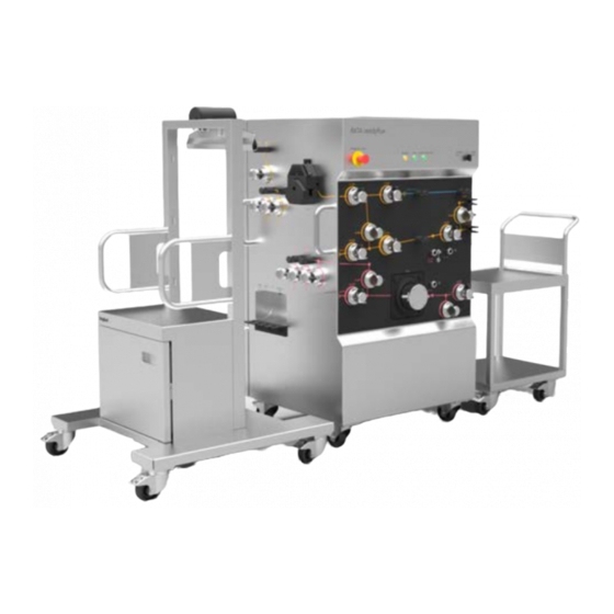
3 System description 3.2 Illustrations Illustrations Introduction This section provides illustrations of the ÄKTA readyflux system. The main features and components are indicated. ÄKTA readyflux instrument The illustration below shows the ÄKTA readyflux instrument. Part Function ÄKTA readyflux cabinet transfer side ÄKTA readyflux cabinet permeate side ÄKTA readyflux top panel ÄKTA readyflux front panel... - Page 32 3 System description 3.2 Illustrations ÄKTA readyflux top panel The illustration below shows the top panel of the ÄKTA readyflux instrument. Part Function EMERGENCY STOP button POWER, RUN, and PAUSE/CONTINUE indicator lights FLOW KIT INSTALL - RUN - INTEGRITY TEST selector CAUTION The PAUSE/CONTINUE button on the system will toggle between pause and run.
- Page 33 3 System description 3.2 Illustrations ÄKTA readyflux front panel The illustration below shows the front panel of the ÄKTA readyflux instrument. Part Function Transfer valve XV-084 Recirculation valve from permeate XV-085 Transfer to retentate valve XV-086 Pressure control valve PCV-341 Retentate valve to bag XV-052 Feed/buffer inlet valve XV-004 Feed inlet valve from bag XV-005...
- Page 34 3 System description 3.2 Illustrations ÄKTA readyflux cabinet permeate side The illustration below shows the permeate side of the ÄKTA readyflux instrument. Part Function UV sensor AE-131 Position for mounting bracket for hollow fiber cartridges, see Section 3.5.2 Hollow fiber (HF) filters, on page Clamp for pH sensor cable Tube supports Connector for pressure sensor PT-113...
- Page 35 3 System description 3.2 Illustrations Part Function Permeate pump P-203 Inlet valve XV-034 for permeate pump and UV sensor Permeate recirculation inlet valve XV-033 Permeate outlet valve XV-032 Permeate drain valve XV-031 External connectors, see External connectors on page 37 ÄKTA readyflux Operating Instructions 29175550 AE...
- Page 36 3 System description 3.2 Illustrations ÄKTA readyflux cabinet transfer side The illustration below shows the transfer side of the ÄKTA readyflux instrument. Part Function Air filter clamp Air inlet valve XV-081 Air sensor AE-151 Buffer inlet valve XV-082 Product/Fed batch process inlet valve XV-083 Push handle External connectors, see External connectors on page 37...
- Page 37 3 System description 3.2 Illustrations External connectors The illustrations below show the ports for external connectors on ÄKTA readyflux. Ports on the permeate side: Part Function POWER SUPPLY System power supply connector PNEUMATIC AIR Pneumatic air supply SUPPLY CUSTOMER I/O - 1 I/O socket, see Section 3.3.4 CUSTOMER I/O connec- tors, on page 50...
- Page 38 3 System description 3.2 Illustrations Part Function PROFIBUS IN PROFIBUS connector in WE 176 Weight scale connector CUSTOMER I/O - 2 I/O socket, see Section 3.3.4 CUSTOMER I/O connec- tors, on page 50 Bagkart The illustration below shows the Bagkart trolley. Part Function Load cell...
- Page 39 3 System description 3.2 Illustrations Fluxkart The illustration below shows the Fluxkart trolley. Part Function Push handle Spillage collector Swivel casters with brake ÄKTA readyflux Operating Instructions 29175550 AE...
-
Page 40: Components
3 System description 3.3 Components Components About this section This section provides an overview of the different components of ÄKTA readyflux. In this section Section See page 3.3.1 Flow kits 3.3.2 Pumps and valves 3.3.3 Meters and sensors CUSTOMER I/O connectors 3.3.4 ÄKTA readyflux Operating Instructions 29175550 AE... -
Page 41: Flow Kits
3 System description 3.3 Components 3.3.1 Flow kits 3.3.1 Flow kits Flow path ÄKTA readyflux flow kits consist of tubing, sensors, a pump head, and fittings. The flow kit, including pump head and sensors, is disposable. The flow path consists of three parts. Each of the three parts are gamma irradiated at delivery and ready for use with the ÄKTA readyflux instrument. - Page 42 3 System description 3.3 Components 3.3.1 Flow kits For information on how to install a flow kit, see Section 5.1 Flow kit installation, on page Flow kit tubing Flow kit tubing inner diameter (i.d.) dimensions are: • ⅜ inch at drains and low flow circulation paths •...
-
Page 43: Pumps And Valves
3 System description 3.3 Components 3.3.2 Pumps and valves 3.3.2 Pumps and valves Introduction This section describes the components located on the panels of the ÄKTA readyflux instrument: • Front panel • Transfer side panel • Permeate side panel The components' designations are shown in the flow chart in Section 3.4 Flow system, on page Pumps... - Page 44 3 System description 3.3 Components 3.3.2 Pumps and valves Feed pump The feed pump P-201 installed on ÄKTA readyflux is a four piston diaphragm pump. It uses a single-use pump head that is part of the flow kit and that is disposed of after usage.
- Page 45 3 System description 3.3 Components 3.3.2 Pumps and valves Transfer and permeate pumps The transfer (P-202) and permeate (P-203) pump installed on ÄKTA readyflux are peristaltic pumps. Peristaltic pumps can run dry. The occlusion settings knob on the transfer pump and the permeate pump is by default set to 2.
- Page 46 3 System description 3.3 Components 3.3.2 Pumps and valves Pinch valves Pinch valves are used to control the path of the liquid flow through the flowpath. There are 20 pinch valves and one PCV. The valves have manually operated safety locks keeping the tubing in place and preventing the valves from accidentally closing during flow kit installation.
- Page 47 3 System description 3.3 Components 3.3.2 Pumps and valves Note: Valves are either open or closed, except for the PCV valve which can be closed gradually. Note: TMP is controlled by the pressure control valve PCV-341, which is regu- lated by the TMP instruction in UNICORN. Note: Control the PCV valve in manual mode by entering the desired pressure set point in percent (%) in the PCV341_%closed instruction.
-
Page 48: Meters And Sensors
3 System description 3.3 Components 3.3.3 Meters and sensors 3.3.3 Meters and sensors Introduction Sensors that measure pressure, conductivity, temperature, pH, flow and UV are included in the ÄKTA readyflux flow kits. The sensors are disposable and intended for single use only. They are pre-calibrated. The sensors are connected to meter units inside the instrument cabinet. - Page 49 3 System description 3.3 Components 3.3.3 Meters and sensors Sensor Location Conductivity sensor CE-102 and Permeate flow path temperature sensor TE-162 The locations of the conductivity and temperature sensors are also depicted in Flow chart on page Conductivity measurement is temperature compensated and thus dependent on correct temperature readings.
-
Page 50: Customer I/O Connectors
3 System description 3.3 Components 3.3.4 CUSTOMER I/O connectors 3.3.4 CUSTOMER I/O connectors Introduction The CUSTOMER I/O connectors are 9-pole (CUSTOMER I/O - 1) and 15-pole (CUSTOMER I/O - 2) IP67-proof D-sub pin connectors. Matching socket connectors containing a screw terminal block with water tight housing are supplied with the system. - Page 51 3 System description 3.3 Components 3.3.4 CUSTOMER I/O connectors Definition of signal +24V Digital output, Remote alarm Free +ve 4-20 mA, WE-177 Digital ground, Remote alarm -ve 4-20 mA, WE-177 +ve 4-20 mA, WE-178 -ve 4-20 mA, WE-178 Free Signal H, Air sensor AE-152 Signal V, Air sensor AE-152 +24V Digital input, UPS On Free...
-
Page 52: Flow System
3 System description 3.4 Flow system Flow system Flow chart FA 231 XV 081 FA 232 XV 086 XV 041 C&T CE 101 TE 161 XV 004 PT 113 CE 102 C&T TE 162 AE 121 FE 141 Symbol Function Pump Pressure control valve Normally closed valve... - Page 53 3 System description 3.4 Flow system Symbol Function Connector Air filter Load cell Accessory Customer I/O Air sensor Conductivity sensor Flow sensor Pump pH sensor Feed pressure sensor Permeate pressure sensor Retentate pressure sensor Temperature sensor Ultra Violet sensor Weight Feed flow path description The purpose of the feed flow path (red line in the flow chart) is to transfer the feed from the feed source (2D or 3D bag) via the pump to the filter.
- Page 54 3 System description 3.4 Flow system Retentate flow path description Particles or molecules too large to pass through the filter pores are retained and pass along the filter membrane as retentate. The retentate is guided to the retentate outlet through the XV-051 valve, from where it can be pumped back to the feed source and recirculated.
- Page 55 3 System description 3.4 Flow system Maximum pressures The pressure is monitored by three pressure sensors, see Pressure sensors on page The different pressure levels are illustrated with dashed lines in the flow chart below. FA 231 XV 081 FA 232 XV 086 XV 041 C&T...
-
Page 56: Filters
3 System description 3.5 Filters Filters About this section This section provides an overview of the different filter types that can be used with ÄKTA readyflux. In this section Section See page 3.5.1 Flat sheet filters 3.5.2 Hollow fiber (HF) filters ÄKTA readyflux Operating Instructions 29175550 AE... -
Page 57: Flat Sheet Filters
3 System description 3.5 Filters 3.5.1 Flat sheet filters 3.5.1 Flat sheet filters Introduction The ÄKTA readyflux Fluxkart provides a convenient way to position the filter holder at the correct height to match the length of the flow kit tubing. For more information about cassette models and sizes, see Membrane filter cassette specifications, on page... -
Page 58: Hollow Fiber (Hf) Filters
ÄKTA readyflux is designed to operate with hollow fiber cartridges of different sizes. These cartridges are described in the Hollow fiber cartridges for membrane separa- tions Operating Handbook, Cytiva article no. 18116530. Section 5.3.2 Hollow fiber (HF) cartridges, on page 137 for more information on how to install the HF cartridges for a filtration. - Page 59 3 System description 3.5 Filters 3.5.2 Hollow fiber (HF) filters Mounting brackets for hollow fiber cartridges The mounting brackets for hollow fiber cartridges are located on the permeate side of the ÄKTA readyflux instrument. The mounting brackets have a hinged arm where the hollow fiber cartridge is inserted. The hinged arm is secured with a knurled nut.
-
Page 60: Unicorn Control System
3 System description 3.6 UNICORN control system UNICORN control system About this section This section provides an overview of the UNICORN software that is used to operate the ÄKTA readyflux system. In this section Section See page 3.6.1 Introduction 3.6.2 Description of UNICORN 3.6.3 The System Control module... -
Page 61: Introduction
UNICORN is compatible with FDA 21 CFR Part 11. Documentation The UNICORN software phases and the UNICORN user documentation provide complete instructions for programming and for using the software for process control. Contact your local Cytiva representative for advice if required. ÄKTA readyflux Operating Instructions 29175550 AE... -
Page 62: Description Of Unicorn
3 System description 3.6 UNICORN control system 3.6.2 Description of UNICORN 3.6.2 Description of UNICORN Software modules The UNICORN control software consists of four modules: Module Function Administration File handling and administration tasks; for example, definition of systems and managing user profiles. -
Page 63: The System Control Module
3 System description 3.6 UNICORN control system 3.6.3 The System Control module 3.6.3 The System Control module Introduction The System Control module is used to start, view, and control a manual or method run. System Control toolbar buttons The following table shows the System Control toolbar buttons that are referred to in this manual. - Page 64 3 System description 3.6 UNICORN control system 3.6.3 The System Control module ÄKTA readyflux Operating Instructions 29175550 AE...
-
Page 65: Process Picture
3 System description 3.6 UNICORN control system 3.6.4 Process picture 3.6.4 Process picture Introduction The process picture is a pictorial representation of the system and is shown in the Process Picture pane in the System Control module. The process picture displays the current flow path and system parameters during a run and can be used to control the run. - Page 66 3 System description 3.6 UNICORN control system 3.6.4 Process picture Symbol Description Filter Flow path Pressure control valve Active pump (green rotating triangle) Inactive pump (gray triangle) Sensor Open valve Closed valve ÄKTA readyflux Operating Instructions 29175550 AE...
- Page 67 3 System description 3.6 UNICORN control system 3.6.4 Process picture The Idle state When the system is powered on, and all the components are initialized to their default states, the process picture shows the Idle (ready) state of the system. The system state panel says Idle and the different flow paths are illustrated in the colors red, yellow, and blue, as shown in the illustration below.
- Page 68 3 System description 3.6 UNICORN control system 3.6.4 Process picture Color Indication Green Open flow path Gray Closed flow path Note: The optional components are shown in the process picture based on the user selection of components in the Administration module of UNICORN. The Flow kit installation wizard button The Flow kit installation wizard is launched from the Flow Kit installation wizard...
- Page 69 3 System description 3.6 UNICORN control system 3.6.4 Process picture Settings Description Units Change the units for flow and pressure in the process picture. The available options are: Flow: L/h or L/min Pressure: bar or psi Choose the preferred settings and click OK. Pumps Set the values for the three different pumps: Feed: Values for the feed pump...
- Page 70 3 System description 3.6 UNICORN control system 3.6.4 Process picture Settings Description Set the values for the pressure control valve. Enter the preferred values and click OK. Automated- Set the values for the automated values such as TMP, Values DeltaP, CFP, Flux, Shear, and CRV. Enter the preferred values and click OK.
- Page 71 3 System description 3.6 UNICORN control system 3.6.4 Process picture Settings Description DisplayParame- Show or hide all the labels in the process picture. ters Select the Show/Hide Labels check box to show the labels. Pumps WARNING Make sure that a valid flow path exists before running a pump manually.
- Page 72 3 System description 3.6 UNICORN control system 3.6.4 Process picture • click Pumps in the Settings panel. Valves To toggle the valves position between open and close: • Click on the valve symbol in the process picture. Result: A confirmation dialog is displayed. After confirmation, the valve position is changed.
-
Page 73: Warnings And Alarms
3 System description 3.6 UNICORN control system 3.6.5 Warnings and alarms 3.6.5 Warnings and alarms Warnings Warnings are generated to warn operating personnel that process parameters have exceeded preset high and/or low limits. The process method continues after the warning has been acknowledged. Alarm signals If equipment is connected that has lower limits than the system, the alarm levels must be set accordingly. -
Page 74: Installation
4 Installation Installation About this chapter This chapter provides required information to enable users and service personnel to transport, unpack and install the product. In this chapter Section See page Site requirements Transport Unpack the product Setup Power supply Precautions WARNING Before attempting to perform any of the procedures described in this chapter, you must read and understand all contents of the... -
Page 75: Site Requirements
4 Installation 4.1 Site requirements Site requirements Space requirements For space and floor requirement, see external dimensions and weights in Dimensions on page • Make sure that the floor can handle the ÄKTA readyflux weight at fully loaded condi- tions. Please observe that for the weight to be equally distributed over all wheels, the floor must be level and without irregularities. - Page 76 4 Installation 4.1 Site requirements Weight The following table lists the weights of the individual products in the ÄKTA readyflux system. Product Weight (kg) ÄKTA readyflux instrument Bagkart Fluxkart Environmental conditions The following general requirements must be fulfilled: • The ÄKTA readyflux system is intended for indoor use only. •...
- Page 77 Section 8.1 Specifications, on page 172 regarding requirements on media supply and delivery. Computer requirements The use of a Cytiva computer is recommended. A non-Cytiva computer with 64-bit Windows operating system is acceptable if it complies with the requirements in the table below. Components...
- Page 78 4 Installation 4.1 Site requirements NOTICE Any computer used with the equipment shall comply with EN/IEC 60950-1, and be installed and used according to the manufactur- er's instructions. When installing a stand-alone computer, take appropriate precautions to protect the computer from exposure to liquids. ÄKTA readyflux Operating Instructions 29175550 AE...
-
Page 79: Transport
4 Installation 4.2 Transport Transport Introduction This section gives important information that must be considered when transporting the product. Crate dimensions The ÄKTA readyflux instrument is delivered in a crate. The total crate weight, including the ÄKTA readyflux instrument, is 373 kg. Moving the crate Use suitable lifting equipment, such as a pallet lift or forklift, with a minimum capacity to match the weight of the ÄKTA readyflux system plus the transport crate. - Page 80 4 Installation 4.2 Transport Symbol Explanation CAUTION TOP HEAVY. The center of balance is offset and is higher than the center of the crate. Fragile Keep dry This side up Recyclable material ÄKTA readyflux Operating Instructions 29175550 AE...
- Page 81 4 Installation 4.2 Transport Moving when unpacked WARNING Heavy object. Because of the significant weight of the product, great care must be taken not to cause squeezing or crushing inju- ries during movement. At least two, but preferably three or more, people are recommended when moving the unit.
-
Page 82: Unpack The Product
See Unpacking Instructions 29178997 attached to the outside of the crate when unpacking the crate. Precautions WARNING The product must be installed and prepared by Cytiva personnel or a third party authorized by Cytiva. WARNING Move transport crates. Make sure that the lifting equipment has the capacity to safely lift the crate weight. -
Page 83: Setup
4 Installation 4.4 Setup Setup About this section This section provides required information to set up the ÄKTA readyflux system. In this section Section See page 4.4.1 Position the system 4.4.2 Setup of control system and network 4.4.3 Start UNICORN and connect to system 4.4.4 Connect compressed air supply 4.4.5... -
Page 84: Position The System
4 Installation 4.4 Setup 4.4.1 Position the system 4.4.1 Position the system Position the system The area required for positioning the ÄKTA readyflux system is 310 × 286 cm, allowing for at least 100 cm of free space on all sides of the instrument. The space allotted for the system should be sufficient to accommodate the ÄKTA readyflux instrument, Bagkart, and Fluxkart. -
Page 85: Setup Of Control System And Network
4 Installation 4.4 Setup 4.4.2 Setup of control system and network 4.4.2 Setup of control system and network Introduction This section describes the steps that need to be performed to set up the UNICORN control system and network connections. Connect the system to a stand-alone computer Two network cables are delivered with the system and should be connected according to the instruction below:... -
Page 86: Start Unicorn And Connect To System
4 Installation 4.4 Setup 4.4.3 Start UNICORN and connect to system 4.4.3 Start UNICORN and connect to system Introduction This section describes how to start and log on to UNICORN and how to connect the instrument to UNICORN. Note: See UNICORN 7 Administration and Technical manual for more information about how to define a new system, view, import or delete instrument config- urations and edit system properties. - Page 87 4 Installation 4.4 Setup 4.4.3 Start UNICORN and connect to system Set up instrument components Follow the instructions to open and edit components installed with the ÄKTA readyflux system. Step Action Select a system in the System Properties dialog. Note: Only active systems can be edited.
- Page 88 4 Installation 4.4 Setup 4.4.3 Start UNICORN and connect to system Step Action In the System Control module, click Connect to Systems. Result: The Connect to Systems dialog box opens. In the Connect to Systems dialog box, select a system check box, click Control for that system, then click OK.
-
Page 89: Connect Compressed Air Supply
4 Installation 4.4 Setup 4.4.4 Connect compressed air supply 4.4.4 Connect compressed air supply Introduction This section describes how to connect the compressed air supply. For requirements on air supply, see Technical specifications on page 172. Note: Specified supply of compressed air should be maintained. Inadequate air supply will cause malfunction of the instrument and may cause hazards. -
Page 90: Bag And Filter Tubing Connections
4 Installation 4.4 Setup 4.4.5 Bag and filter tubing connections 4.4.5 Bag and filter tubing connections Introduction This section provides guidelines for the tubing connections to bags and filters in the ÄKTA readyflux system. Connection diagram Flow chart on page 52 for a schematic diagram of the connections in the ÄKTA readyflux system. - Page 91 4 Installation 4.4 Setup 4.4.5 Bag and filter tubing connections ÄKTA readyflux Operating Instructions 29175550 AE...
-
Page 92: Power Supply
4 Installation 4.5 Power supply Power supply Introduction This section describes the electrical connections to the instrument. Precautions WARNING Protective ground. The product must always be connected to a grounded power outlet. WARNING National Codes and standards (NEC, VDE, BSI, IEC, UL etc.) and local codes outline provisions for safely installing electrical equipment. - Page 93 WARNING Only authorized Cytiva personnel may perform service, installation and manitenance of components inside the cabinet. Note: Only authorized Cytiva personnel may perform service, installation and manitenance of components outside the cabinet. Main power supply wire colors and tags The power cord wires are color coded as shown in the table below. They must be connected to the corresponding terminals in the fixed power supply or to a connector compatible with IEC 60309.
- Page 94 Ground fault breaker ÄKTA readyflux is not equipped with a general Ground Fault Circuit Breaker and it is not an option that is available from Cytiva. However, if ground fault protection for the system is desired, • a Ground Fault Circuit Interruptor may be installed, or •...
-
Page 95: Operation
5 Operation Operation About this chapter This chapter provides the information required to safely operate the product. In this chapter Section See page Flow kit installation Bag installation Filter installation Installation test Calibration Perform a run Procedures after a run Precautions WARNING Before attempting to perform any of the procedures described in... - Page 96 Only use chemicals listed in the Chemical Resistance information. The wetted parts of the product may be damaged by chemicals not listed in the Chemical Resistance information. Contact your Cytiva representative before using chemicals that are not listed. for more information.
-
Page 97: Flow Kit Installation
5 Operation 5.1 Flow kit installation Flow kit installation About this section This section provides the information required to install the flow kit. In this section Section See page 5.1.1 Preparations 5.1.2 Flow kit package 5.1.3 Install the flow kit 5.1.4 Flow kit installation test Precautions... - Page 98 Do not leave a flow kit mounted on the system for an excessively long time. The tubing walls may stick together where the tubing is squeezed, possibly causing high pressure alarms when running the system. NOTICE Only use flow kits supplied by Cytiva. ÄKTA readyflux Operating Instructions 29175550 AE...
-
Page 99: Preparations
5 Operation 5.1 Flow kit installation 5.1.1 Preparations 5.1.1 Preparations Disinfectant solution A suitable disinfectant solution must be available for cleaning the external surfaces of system and flow kit. 70% ethanol or 2-propanol (isopropanol) can be used for sanitiza- tion. Note: Desinfection is not necessary for flow kits with ReadyMate™... -
Page 100: Flow Kit Package
5 Operation 5.1 Flow kit installation 5.1.2 Flow kit package 5.1.2 Flow kit package Packaging The flow kit is delivered in three parts. Part of the flow path Permeate flow path tubing, pump tubing and sensors Retentate and transfer flow path tubing, pump tubing and sensors Feed flow path tubing, feed pump head and sensor ÄKTA readyflux flow kits are packed and delivered in double plastic bags. -
Page 101: Install The Flow Kit
5 Operation 5.1 Flow kit installation 5.1.3 Install the flow kit 5.1.3 Install the flow kit Introduction This section contains a step-by-step description of how to install a flow kit onto the ÄKTA readyflux cabinet. Always use the ÄKTA readyflux flow kit installation wizard when installing a new flow kit. - Page 102 5 Operation 5.1 Flow kit installation 5.1.3 Install the flow kit Mount the tubing of the permeate flow path. Mount the tubing of the permeate flow path on page 105. Mount the tubing of the retentate and transfer flow path. Mount the tubing of the retentate and transfer flow path, on page 108.
- Page 103 5 Operation 5.1 Flow kit installation 5.1.3 Install the flow kit Step Action Select the type of flow kit, Flow Kit, Flow Kit plus, or Custom Kit, and the type of end connector, TC or ReadyMate. Registration details Follow the instructions below for entering the registration details of the flow kit. Note: The Custom kit is by default equipped with ReadyMate end connections.
- Page 104 5 Operation 5.1 Flow kit installation 5.1.3 Install the flow kit Step Action Turn the FLOW KIT INSTALL - RUN - INTEGRITY TEST selector to the FLOW KIT INSTALL position. FLOW KIT INTEGRITY INSTALL TEST Note: The FLOW KIT INSTALL setting will open all valves. Note: Do not run any method when in the FLOW KIT INSTALL setting.
- Page 105 5 Operation 5.1 Flow kit installation 5.1.3 Install the flow kit Step Action Open the pump head of transfer pump P-202 and permeate pump P-203. Move the lever on the pumps to the left (counterclockwise). Mount the tubing of the permeate flow path Follow the instructions below to mount the tubing of the permeate flow path.
- Page 106 5 Operation 5.1 Flow kit installation 5.1.3 Install the flow kit Step Action • If the flow kit is not supplied with a UV sensor: Hold the permeate recirculation tubing and the sensors tubing in one hand and the white pump tubing in the other hand. •...
- Page 107 5 Operation 5.1 Flow kit installation 5.1.3 Install the flow kit Step Action Place the white pump tubing into permeate pump P-203. Use the free hand to insert the tubing into the two pinch valves XV-033 and XV-034 on the permeate side. ÄKTA readyflux Operating Instructions 29175550 AE...
- Page 108 5 Operation 5.1 Flow kit installation 5.1.3 Install the flow kit Step Action Use the free hand to align the permeate recirculation tubing around the cabinet and place it into the tube supports. Insert the tubing into the two pinch valves XV-031 and XV-032 on the permeate side and place the sensor tubing into the tube supports.
- Page 109 5 Operation 5.1 Flow kit installation 5.1.3 Install the flow kit Step Action Tear open the plastic bag. Hold the air filter tubing to be placed into the clamp FA-231 and the H-junc- tion tubing in one hand and the air filter tubing to be placed into the FA-232 clamp in the other hand.
- Page 110 5 Operation 5.1 Flow kit installation 5.1.3 Install the flow kit Step Action Insert the tubing with the air filter into the air filter clamp FA-232. Insert the tubing into the two pinch valves PCV-341 and XV-052. Transfer the H-junction tubing to the other hand. ÄKTA readyflux Operating Instructions 29175550 AE...
- Page 111 5 Operation 5.1 Flow kit installation 5.1.3 Install the flow kit Step Action Align the H-junction tubing and insert it into the three pinch valves XV-086, XV-085, and XV-084. Place the tubing into transfer pump P-202. Insert the tubing with the air filter into the air filter clamp FA-231 on the transfer side.
- Page 112 5 Operation 5.1 Flow kit installation 5.1.3 Install the flow kit Step Action Insert the tubing into the three pinch valves XV-083, XV-082, and XV-081 on the transfer side, and into the air sensor AE-151. Mount the tubing of the feed flow path Follow the instructions below to mount the feed flow path.
- Page 113 5 Operation 5.1 Flow kit installation 5.1.3 Install the flow kit Step Action Hold the tubing before the feed pump and the braided tubing in one hand and the tubing after the pump head in the other hand. Insert the tubing into the two pinch valves XV-006 and XV-071 on the cabinet front.
- Page 114 5 Operation 5.1 Flow kit installation 5.1.3 Install the flow kit Step Action Insert the tubing into the two pinch valves XV-004 and XV-005. Insert the tubing into the three pinch valves XV-001, XV-002, and XV-003 on the transfer side. Place the pressure plate on pump P-201.
- Page 115 5 Operation 5.1 Flow kit installation 5.1.3 Install the flow kit Step Action Hold the pressure plate and hand tighten the screws into pump by using a hex key. Attach the drive adapter to the torque wrench and tighten the screws to 8 Nm, diagonally first and circular at the end.
- Page 116 5 Operation 5.1 Flow kit installation 5.1.3 Install the flow kit Step Action Identify the sensors and their connectors on the permeate side and remove the sensor caps from the system. ÄKTA readyflux Operating Instructions 29175550 AE...
- Page 117 5 Operation 5.1 Flow kit installation 5.1.3 Install the flow kit Step Action Plug in the pressure sensor PT-113 cable as follows: a. Align the white lines (A) and (B) on the connectors. b. Press the connectors together firmly. Repeat for PT-111 and PT-112 on the cabinet front. ÄKTA readyflux Operating Instructions 29175550 AE...
- Page 118 5 Operation 5.1 Flow kit installation 5.1.3 Install the flow kit Step Action Plug in the conductivity sensor CE-102 cable as follows: a. Align the keyway (1) on the connector of the sensor with the tab (1) inside the mating connector on the cable. b.
- Page 119 5 Operation 5.1 Flow kit installation 5.1.3 Install the flow kit Step Action Plug in the flow sensor FE-141 cable as follows: a. Align the arrows on both connectors. b. Press the connectors together firmly. Connect the end connections of the flow kit using TC end connectors If the flow kit is supplied with TC end connectors, follow the instructions below to connect the end connections of the flow kit.
- Page 120 5 Operation 5.1 Flow kit installation 5.1.3 Install the flow kit Step Action Insert the O-ring into the tube ends and align the tube ends. Apply a standard plastic sanitary clamp, a disposable TC clamp, or a stainless steel sanitary clamp to the connector assembly for connection. Repeat for filter and feed bag connections.
- Page 121 5 Operation 5.1 Flow kit installation 5.1.3 Install the flow kit Step Action Remove the protective cap and printed liner from the permeate recircula- tion and transfer tubing at XV-085. Tilt the connectors to engage the hook of one connector with the slot of the other. Bring the connectors together with an audible click.
- Page 122 5 Operation 5.1 Flow kit installation 5.1.3 Install the flow kit Step Action Apply a standard plastic sanitary clamp, a disposable ReadyClamp, or a stainless steel sanitary clamp to the connector assembly for connection. Repeat for filter and feed bag connections. Note: Always operate instrument with the feed bag connected to feed and reten- tate lines.
- Page 123 5 Operation 5.1 Flow kit installation 5.1.3 Install the flow kit Step Action Close the pump heads of transfer pump P-202 and permeate pump P-203 as follows: • Move the lever to the right (clockwise). Turn the FLOW KIT INSTALL - RUN - INTEGRITY TEST selector to the RUN position.
-
Page 124: Flow Kit Installation Test
5 Operation 5.1 Flow kit installation 5.1.4 Flow kit installation test 5.1.4 Flow kit installation test Introduction The flow kit installation test checks that the flow kit is correctly installed and that the sensors are responding to the test points. The flow kit installation test takes approxi- mately 5 minutes. - Page 125 5 Operation 5.1 Flow kit installation 5.1.4 Flow kit installation test • Tee connector, O-rings, TC clamps, and flexible tubing • Test solution: 10 L of 1% (v/v) acetone and 1.0 M sodium chloride in a suitable container. See also the Test solution preparation protocol template on the system Note: The test solution must be freshly prepared before a flow kit installation test is performed, to prevent the acetone from evaporating.
- Page 126 5 Operation 5.1 Flow kit installation 5.1.4 Flow kit installation test Step Action Import the Flow Kit installation test method from CD or Web Open it in Method editor For Flow Kit plus configuration, update the pH calibration slope and zero point values in AE121_pH calibration settings block located in test instructions tab of method Save it...
- Page 127 5 Operation 5.1 Flow kit installation 5.1.4 Flow kit installation test Report section Information Questions Product identification details: • Bar code of flow kit parts • pH sensor details • Protocol for text solution preparation • Mode for entering codes Method notes •...
-
Page 128: Bag Installation
5 Operation 5.2 Bag installation Bag installation About this section This section provides required information to install bags in the ÄKTA readyflux system. In this section Section See page 5.2.1 2D hanging bag (Bagkart) 5.2.2 3D bag (XDUO or XDM) ÄKTA readyflux Operating Instructions 29175550 AE... -
Page 129: Hanging Bag (Bagkart)
5 Operation 5.2 Bag installation 5.2.1 2D hanging bag (Bagkart) 5.2.1 2D hanging bag (Bagkart) Introduction This section describes how to install 5 L, 10 L and 20 L 2D-hanging bags (Bagkart) in the ÄKTA readyflux system. Illustration of a 2D hanging bag Part Function Mounting rod... - Page 130 5 Operation 5.2 Bag installation 5.2.1 2D hanging bag (Bagkart) CAUTION The maximum weight of the 2D Bag on the Bagkart is 25 kg. Bagkart must only be tared with an empty bag and empty flow kits. Incorrect taring will result in overload of the Bagkart trolley or the bag, which may result in bag burst.
- Page 131 5 Operation 5.2 Bag installation 5.2.1 2D hanging bag (Bagkart) Step Action Make sure that Bagkart (WE176) is selected under Component types →FeedBag Weight, see Set up instrument components, on page Note: Bagkart is enabled by default. ÄKTA readyflux Operating Instructions 29175550 AE...
-
Page 132: Bag (Xduo Or Xdm)
XDUO Mixer Operating Instructions or FlexFactory XDM S UF Mixer Operating Instruc- tions. Note: Contact a Cytiva service engineer when connecting XDUO or XDM S UF mixers to the ÄKTA readyflux system. Installation Follow the instruction below to install a 3D bag (XDUO or XDM) in the ÄKTA readyflux system. - Page 133 5 Operation 5.2 Bag installation 5.2.2 3D bag (XDUO or XDM) Step Action XDUO For XDUO mixer, make sure the following Component types are selected as listed below, see Set up instrument components, on page • Mixer (XDUO/XDM) Options:Mixer (XDUO) •...
-
Page 134: Filter Installation
5 Operation 5.3 Filter installation Filter installation About this section This section provides required information to install filters in the ÄKTA readyflux system. In this section Section See page 5.3.1 Membrane filter cassettes 5.3.2 Hollow fiber (HF) cartridges ÄKTA readyflux Operating Instructions 29175550 AE... -
Page 135: Membrane Filter Cassettes
5 Operation 5.3 Filter installation 5.3.1 Membrane filter cassettes 5.3.1 Membrane filter cassettes Introduction This section describes how to place the cassette holder on the Fluxkart and connect to the system. General preparation of the cassettes Follow the general preparations below before installing the cassettes. Step Action If the filter cassettes to be used are new, it is strongly recommended to... - Page 136 5 Operation 5.3 Filter installation 5.3.1 Membrane filter cassettes Step Action Turn the knob on the top panel to INTEGRITY TEST. FLOW KIT INTEGRITY INSTALL TEST Perform the integrity test of the filter by connecting an external air integrity tester to the XV-041 filter inlet. INTEGRITY TEST will open valves XV-031, XV-032 and XV-041 and close valves XV-006 and XV-051.
-
Page 137: Hollow Fiber (Hf) Cartridges
5 Operation 5.3 Filter installation 5.3.2 Hollow fiber (HF) cartridges 5.3.2 Hollow fiber (HF) cartridges Introduction This section describes how to install HF cartridges in the ÄKTA readyflux system. Installation Follow the instruction below to install a HF cartridge. Step Action Make sure that the system is configured for using HF cartridges of the intended size. - Page 138 5 Operation 5.3 Filter installation 5.3.2 Hollow fiber (HF) cartridges Step Action Connect the top outlet of the HF cartridge to the flow kit retentate inlet at XV-051. Note: If necessary, use adapters or 180 degree tubing to match the end connec- tions.
-
Page 139: Installation Test
5 Operation 5.4 Installation test Installation test About this section This section provides the information required to perform the system installation test. The test enables users and service personnel to check that all components are func- tioning after installation of the system, components or flow kit. In this section Section See page... -
Page 140: About The System Installation Test
5 Operation 5.4 Installation test 5.4.1 About the system installation test 5.4.1 About the system installation test Introduction The installation test checks that the system is correctly installed and that the modules are functioning properly. An installation test takes approximately 60 minutes. Note: An installation test should always be performed after installing a new system or new parts. - Page 141 5 Operation 5.4 Installation test 5.4.1 About the system installation test Stage Description The air bubble detector checks if air bubbles are present in the system during cleaning of the flow kit. When the test is finished, a test report ( AKTA_ready- flux_test_report.txt ) is generated with a FAIL or PASS result for each module.
-
Page 142: Running A System Installation Test
5 Operation 5.4 Installation test 5.4.2 Running a system installation test 5.4.2 Running a system installation test Equipment and chemicals The following equipment and chemicals are required for the system installation test: • Flow Kit with TC end connections containing Conductivity, pH & UV on permeate section •... - Page 143 5 Operation 5.4 Installation test 5.4.2 Running a system installation test WARNING Over-pressure. Never block the outlet tubing with, for instance, stop plugs, since this will create over-pressure and might result in injury. Start the installation test Follow the instructions below to start the system installation test. Step Action Import the system installation test method from CD or Web.
-
Page 144: The Installation Test Report
5 Operation 5.4 Installation test 5.4.3 The installation test report 5.4.3 The installation test report Two test reports are generated when the test is finished. • A UNICORN result file with a name containing Installation Test System which can be accessed using Evaluation module. •... - Page 145 5 Operation 5.4 Installation test 5.4.3 The installation test report Report section Information Questions Product identification details: • Bar code of flow kit parts • pH sensor details • Protocol for text solution preparation • Mode for entering codes Method notes •...
-
Page 146: Calibration
5 Operation 5.5 Calibration Calibration Introduction This section describes how to calibrate the components. Calibration of 2D bag To perform a calibration of the 2D bag, a pre-calibrated hanging weight of known weight must be used. Follow these steps to perform a calibration: Step Action Start a run. - Page 147 5 Operation 5.5 Calibration Step Action Set the RPM of the pump (P20x_RPM) under Manual instruction →Special and click Execute the run. Let the pump run for couple of minutes to make sure that no air bubbles are present in the system tubings. Measure the flowrate in LPM using the reference instrument between time point 0 and time point T.
- Page 148 5 Operation 5.5 Calibration Step Action In the System Control module, on the Manual menu, click Execute Manual Instructions. Select the instruction AE131UV_StraylightCalib and click Execute. A warning message will be displayed when the stray light calibration has started. This warning message is information only. The calibration will proceed regardless of whether the user closes the warning message (by clicking Acknowledge) or not.
-
Page 149: Perform A Run
5 Operation 5.6 Perform a run Perform a run About this section This section describes the safety aspects of performing a run. For detailed information about how to run the system, see UNICORN 7 System Control manual and ÄKTA readyflux software manual. In this section Section See page... -
Page 150: Before You Start
5 Operation 5.6 Perform a run 5.6.1 Before you start 5.6.1 Before you start Introduction Before starting a run, it is necessary to read and understand the information in this section and to perform the checks listed below. Prerequisites Make sure that the system is correctly prepared. Check that: •... - Page 151 5 Operation 5.6 Perform a run 5.6.1 Before you start If you want to... then... click the Continue button. resume a held or paused method run Note: An ended method cannot be continued. click the End button. permanently end the run, stop all pumps and reset the valves to their default posi- tions Note:...
-
Page 152: Start And Monitor A Method Run
5 Operation 5.6 Perform a run 5.6.2 Start and monitor a method run 5.6.2 Start and monitor a method run Introduction This section describes how to start a run using a previously created method and how to monitor the run. For more information on method creation, see UNICORN 7 Method manual. - Page 153 5 Operation 5.6 Perform a run 5.6.2 Start and monitor a method run Monitor the run You can follow the on-going method run in the System Control module. The current system state is shown in the System state panel in the Run Data pane. For example, it may say Method Run, Wash or Hold.
-
Page 154: Procedures After A Run
5 Operation 5.7 Procedures after a run Procedures after a run Introduction This section describes how to prepare the flow kit and the filter for disposal and how to shut down the system after a run. The flow kit and the filter should be disposed of in accordance with local regulations. Prepare the flow kit and the filter for disposal WARNING... - Page 155 5 Operation 5.7 Procedures after a run Dismantle flow kit and the filter for disposal After preparation, follow these steps to dismantle and remove the flow kit and the filter for disposal: Step Action Disconnect all flow kit sensors from the connector cables. Note: It is important to pull back the FE-141 latch to disconnect the cable, as shown in image.
- Page 156 5 Operation 5.7 Procedures after a run If you want to... then... on the File menu, click Log off. log off UNICORN Result: All open UNICORN modules close and the Log On dialog box opens. on the File menu, click Exit UNICORN. exit UNICORN Result: All open UNICORN modules close.
-
Page 157: Maintenance
6 Maintenance Maintenance About this chapter This chapter provides information to enable users and service personnel to clean, maintain, calibrate and store the product. Contact Cytiva service personnel before any maintenance. In this chapter Section See page Cleaning before planned service... -
Page 158: Cleaning Before Planned Service
6 Maintenance 6.1 Cleaning before planned service Cleaning before planned service Cleaning before planned maintenance/service To ensure the protection and safety of service personnel, all equipment and work areas must be clean and free of any hazardous contaminants before a Service Engineer starts maintenance work. -
Page 159: Daily Maintenance
It is important that the user is always attentive about the status and operation of the equipment. The cause of any abnormal behavior or aberrant noise should be examined and removed. If the problem is non-trivial, contact your local Cytiva representative. General cleaning... - Page 160 6 Maintenance 6.2 Daily maintenance Cleaning after each run • Clean the shaft of the feed pump P-201 after the flow kit has been uninstalled. • Clean the rollers of the pumps P-202 and P-203 after the flow kit has been unin- stalled.
-
Page 161: Yearly Maintenance
Preventive maintenance must be performed on a yearly basis by qualified service personnel authorized by Cytiva. Different service agreements are available. Contact your Cytiva representative for more information. This section provides instructions for yearly maintenance. Pneumatic valve opening and closing... -
Page 162: Spare Parts
6 Maintenance 6.4 Spare parts Spare parts Introduction Apart from the flow kits, ÄKTA readyflux has very few parts that a user may need to replace. Normally, parts are checked and, if necessary, replaced by service personnel during preventive maintenance. For a list of available accessories and spare parts see Section 8.4 Ordering information, on page 180. -
Page 163: Storage
6 Maintenance 6.5 Storage Storage If the system is not used for a longer time period (more than a few days): • Remove the flow kit (see Section 5.7 Procedures after a run, on page 154). • Clean the cabinet (see General cleaning on page 159). -
Page 164: Troubleshooting
Section 5.4 Installation test, on page 139. If the suggested actions in this guide do not solve the problem or if the problem is not covered by this guide, contact your Cytiva representative. Precautions WARNING Before attempting to perform any of the procedures described in... - Page 165 Check that the power to the system is available. If the power supply is reaching the system and the system is not powering ON, contact a Cytiva representative. Note: If the power failure also affects the computer, no data can be stored and the run must be restarted.
- Page 166 7 Troubleshooting Problem Corrective action Position sensor failure. Check If the valve can be opened/closed with System Control or Manual Instructions. If Valve error persists, contact a Cytiva representative. Feed pump Problem Corrective action Pump not working • Emergency button has been pressed. Reset according to Restart after emergency shutdown or power failure on page •...
- Page 167 • No air supply to the system. • Incorrect method. Check by entering PCV_%Closed to > 10%. • If none of the above, contact Cytiva service personnel. Check by partially closing the valve by entering PCV_%Colsed to Back pressure not attained >...
- Page 168 7 Troubleshooting Conductivity and temperature monitors Problem Corrective action Incorrect conductivity reading • Make sure that the conductivity and temperature sensor is properly connected to the system cable. See Section 5.1.3 Install the flow kit, on page 101 for mounting instructions. •...
- Page 169 7 Troubleshooting UV monitor Problem Corrective action Incorrect UV reading • Condensation on the flow cell window. Check that the UV cell and sensor windows are clean and dry. Wipe with a soft tissue if necessary. • Make sure that the UV cell is properly inserted. •...
- Page 170 7 Troubleshooting Bagkart Problem Corrective action Incorrect weight • Make sure that the weighing scale is properly connected to the system connector. See Section 5.2.1 2D hanging bag (Bagkart), on page 129 for weighing scale connection instructions. • Make sure Zero calibration is performed prior to the run with no load condition.
-
Page 171: Reference Information
8 Reference information Reference information About this chapter This chapter lists the technical specifications of ÄKTA readyflux. The chapter also includes a list of wetted materials, a chemical resistance guide, ordering information, and Health and Safety Declaration form for service. In this chapter Section See page... -
Page 172: Specifications
8 Reference information 8.1 Specifications Specifications Technical specifications Property Value Dimensions 110 × 86 ×152 cm (width × depth × height) Weight 280 kg Control system UNICORN 7.1 or higher versions of UNICORN Supply voltage 100 to 240 V AC ± 10% Frequency 50/60Hz Max. - Page 173 8 Reference information 8.1 Specifications Capacity Property Value Pump, feed, operating flow Speed: 12 to 2400 rpm Flow: 2 to 18 L/min Pump, transfer, operating flow Speed: 20 to 500 rpm Flow: 0.5 to 6 L/min Pump, permeate Speed: 10 to 250 rpm Flow: 0.05 to 1.6 L/min Flow kit specifications Property...
- Page 174 8 Reference information 8.1 Specifications Sensor Range Acceptance range Temperature (retentate 4°C to 50°C 4°C to 50°C and permeate) pH 3 to 10 pH 3 to 10 -100 to 1000 mAU Weight 0 to 50 kg 0 to 25 kg The liquid and the surrounding room should be maintained at the same temperature.
- Page 175 8 Reference information 8.1 Specifications Filter size Area Min feed Max feed Perm flow Perm flow range flow (L/ flow (L/ min area max area min) min) (L/min) (L/min) 8, 9 0.36 to 1.2 ≤ 5.4 ≤ 36 ~0.6 ~2.0 At a shear rate of 4000/s, C-lumen At a shear rate of 12000/s, E-lumen Hollow fiber sizes 8 and 9 (standard and RTP) can only be used in the ÄKTA readyflux system at a...
-
Page 176: Process Wetted Materials
8 Reference information 8.2 Process wetted materials Process wetted materials Materials used The materials used in the manufacturing of ÄKTA readyflux have been chosen for their biological and chemical compatibility with the solvents used during operation. The system has also been designed to comply with the varying hygienic requirements at the different stages of development and production. -
Page 177: Chemical Resistance
8 Reference information 8.3 Chemical resistance Chemical resistance Allowed chemicals for external surfaces, cabinet The following chemicals shall be used when cleaning the system: • Water with weak detergent should be used for daily cleaning of the cabinet. • 70% ethanol or 2-propanol (isopropanol) can be used for sanitization. The external/outer surfaces of the ÄKTA readyflux system shall be resistant to the following chemicals: Chemical... - Page 178 Also make sure that your process chemicals do not damage the system components, compromising the safety of the system. Contact your local Cytiva representative if you are not sure of the compatibility of your chemicals.
- Page 179 8 Reference information 8.3 Chemical resistance Chemical Concentra- Time/cycle No. of cycles Tempera- tion ture Isopropanol 25°C Mercaptoe- 20 mM 25°C thanol PEG 500 25°C PEG 1000 25°C PEG 5000 25°C Phosphoric 25°C acid Pluronic® 25°C F-68 25°C Sodium 25°C chloride Sodium 0.01 N...
-
Page 180: Ordering Information
8 Reference information 8.4 Ordering information Ordering information Introduction This section contains ordering information for ÄKTA readyflux flow kits and ÄKTA readyflux accessories and spare parts, and for related literature. ÄKTA readyflux accessories Product Product code Bagkart 29151500 Fluxkart 29245919 Hollow fiber filter holder, Single filter 29258287 Hollow fiber filter holder, Two filters... - Page 181 8 Reference information 8.4 Ordering information Product Product code RMRM Jumper Y manifold 12410195 ÄKTA readyflux IQ/OQ Product Product code IQOQ Performance 28992657 ÄKTA readyflux spare parts Product Product code CU-960 28938854 PCV controller 29226930 Quattroflow pump assembly 29168412 Peristaltic pump assembly 29168417 Load cell 29191023...
-
Page 182: Recycling Information
8 Reference information 8.5 Recycling information Recycling information Introduction This section contains information about the decommissioning of the product. CAUTION Always use appropriate personal protective equipment when decommissioning the equipment. Decontamination The product must be decontaminated before decommissioning. All local regulations must be followed with regard to scrapping of the equipment. - Page 183 8 Reference information 8.5 Recycling information Step Action Dispose of electronic components as specified by local regulations depending on material used in the construction of the components. Follow local and/or national/federal requirements for disposal of the electronic components. Instructions for disposal of the flow Follow the instructions below for disposal of the flow kit.
-
Page 184: Regulatory Information
8 Reference information 8.6 Regulatory information Regulatory information Introduction This section lists the regulations and standards that apply to the product. In this section Section See page 8.6.1 Contact information 8.6.2 European Union and European Economic Area 8.6.3 Eurasian Economic Union Евразийский... -
Page 185: Contact Information
Manufacturing information The table below summarizes the required manufacturing information. Requirement Information Name and address of manufacturer Cytiva Sweden AB Björkgatan 30 SE 751 84 Uppsala Sweden Telephone number of manufacturer + 46 771 400 600 ÄKTA readyflux Operating Instructions 29175550 AE... -
Page 186: European Union And European Economic Area
8 Reference information 8.6 Regulatory information 8.6.2 European Union and European Economic Area 8.6.2 European Union and European Economic Area Introduction This section describes regulatory information for the European Union and European Economic Area that applies to the equipment. Conformity with EU Directives See the EU Declaration of Conformity for the directives and regulations that apply for the CE marking. -
Page 187: Eurasian Economic Union
Presnenskaya nab., 10, fl. 12, pr. III, room 6 Telephone: + 7 495 739 6931 Fax nr: + 7 495 739 6932 E-mail: rucis@cytiva.com Информация о производителе и импортере В следующей таблице приводится сводная информация о производителе и импортере, согласно требованиям Технических регламентов Таможенного союза... - Page 188 Пресненская наб., д. 10, эт. 12, пом. III, ком. 6 Телефон: + 7 495 739 6931 Факс: + 7 495 739 6932 Адрес электронной почты: rucis@cytiva.com Description of symbol on the system label Описание обозначения на этикетке системы This Eurasian compliance mark indicates that the product is...
-
Page 189: Regulations For North America
Note: The user is cautioned that any changes or modifications not expressly approved by Cytiva could void the user’s authority to operate the equip- ment. This equipment has been tested and found to comply with the limits for a Class A digital device, pursuant to part 15 of the FCC Rules. -
Page 190: Regulatory Statements
8 Reference information 8.6 Regulatory information 8.6.5 Regulatory statements 8.6.5 Regulatory statements Introduction This section shows regulatory statements that apply to regional requirements. EMC emission, CISPR 11: Group 1, Class A statement NOTICE This equipment is not intended for use in residential environments and may not provide adequate protection to radio reception in such environments. -
Page 191: Other Regulations And Standards
8 Reference information 8.6 Regulatory information 8.6.6 Other regulations and standards 8.6.6 Other regulations and standards Introduction This section describes the standards that apply to the product. Biological and chemical compatibility The Wetted parts of the ÄKTA readyflux system meet the material requirements of the following standards and regulations: Requirement Description... -
Page 192: Declaration Of Hazardous Substances (Dohs)
8 Reference information 8.6 Regulatory information 8.6.7 Declaration of Hazardous Substances (DoHS) 8.6.7 Declaration of Hazardous Substances (DoHS) 根据 SJ/T11364-2014《电子电气产品有害物质限制使用标识要求》特提供如下 有关污染控制方面的信息。 The following product pollution control information is provided according to SJ/ T11364-2014 Marking for Restriction of Hazardous Substances caused by electrical and electronic products. - Page 193 8 Reference information 8.6 Regulatory information 8.6.7 Declaration of Hazardous Substances (DoHS) 有害物质的名称及含量 Name and Concentration of Hazardous Substances 产品中有害物质的名称及含量 Table of Hazardous Substances’ Name and Concentration 部件名称 有害物质 Component Hazardous substance name 铅 汞 镉 六价铬 多溴联苯 多溴二苯醚 (Pb) (Hg) (Cd) (Cr(VI))
-
Page 194: Health And Safety Declaration Form
Service Ticket #: To make the mutual protection and safety of Cytiva service personnel and our customers, all equipment and work areas must be clean and free of any hazardous contaminants before a Service Engineer starts a repair. To avoid delays in the servicing of your equipment, complete this checklist and present it to the Service Engineer upon arrival. - Page 195 To make sure the mutual protection and safety of Cytiva personnel, our customers, transportation personnel and our environment, all equipment must be clean and free of any hazardous contaminants before shipping to Cytiva. To avoid delays in the processing of your equipment, complete this checklist and include it with your return.
-
Page 196: More Information
Hardware Product Documentation binders. For lists of documents, see Section 1.3 Associated documentation, on page Your local Cytiva representative will also be able to suggest recommended spare parts and accessories. Remaining aspects Contact your local Cytiva representative for advice regarding: •... -
Page 197: Index
Index Index Computer requirements, 77 Conductivity sensor, 48, 115 Abbreviations, 10 connect, 115 Accessories, 180, 196 Connect, 89, 92 Air sensor, 49 compressed air, 89 Air supply, 89 power supply, 92 connect, 89 Crate, 79 ÄKTA readyflux , 29–34, 36, 75, 76, dimensions, 79 85, 172 move, 79... - Page 198 Index Flammable liquids, 14 Illustration, 29 precautions, 14 system, 29 Flow kit, 30, 41, 42, 99–103, 122, Important user information, 6 124, 154, 173, 180 Installation test, 140, 143 associated products, 30 Monitor, 143 close valve locks, 122 system, 140 disinfectant solution, 99 Installation wizard, 101 disposal, 154...
- Page 199 Index Permeate flow path, 54, 105 ReadyMate, 120 installation, 105 connect, 120 Permeate pump, 45, 105, 122 Recycling information, 182 close, 122 decontamination, 182 open, 105 disposal of electrical compo- Personal protection, 14 nents, 182 precautions, 14 Regulatory information, 184 pH electrode, 49 Retentate flow path, 54, 108 pH sensor, 49, 118...
- Page 200 Index System Control module, 63 description, 63 Weight, 76 icons, 63 Wetted materials, 176 System installation test, 140, 142 Wheels, 162 preparations, 142 System label, 23 replace, 162 System operation, 18 precautions, 18 TC clamp, 119 connect, 119 Temperature, 49 changes, 49 Temperature sensor, 48 Training, 196...
- Page 201 Page intentionally left blank...
- Page 202 Standard Software End-User License Agreement is available on request. All goods and services are sold subject to the terms and conditions of sale of the supplying company operating within the Cytiva business. A copy of those terms and conditions is available on request. Contact your local Cytiva representative for the most current information.
Need help?
Do you have a question about the AKTA readyflux and is the answer not in the manual?
Questions and answers