cytiva AKTA go Operating Instructions Manual
Hide thumbs
Also See for AKTA go:
- Operating instructions manual (130 pages) ,
- Unpacking instructions (4 pages)
Table of Contents
Advertisement
Advertisement
Table of Contents

Related Manuals for cytiva AKTA go


Summary of Contents for cytiva AKTA go
- Page 1 ÄKTA go™ Operating Instructions Original instructions ÄKTA go cytiva.com...
-
Page 2: Table Of Contents
Table of Contents Table of Contents Introduction ......................4 Important user information ........................5 About this manual ............................6 Associated documentation ........................7 Abbreviations ..............................9 Safety instructions ..................... 10 Safety precautions ............................11 Labels and symbols ............................15 Emergency procedures ..........................16 System description .................... - Page 3 Table of Contents Monitor or interact with the run ....................... 87 Evaluate the run ............................. 88 Procedures after the run ..........................90 Maintenance ....................... 93 Clean the instrument externally ......................94 Perform system Cleaning-In-Place (CIP) ....................95 Replace pump rinsing liquid ........................99 Replace the main fuses ..........................
-
Page 4: Introduction
1 Introduction Introduction This chapter contains information about this manual and associated user documenta- tion, important user information and intended use of ÄKTA go™. In this chapter Section See page Important user information About this manual Associated documentation Abbreviations ÄKTA go Operating Instructions 29360951 AE... -
Page 5: Important User Information
1 Introduction 1.1 Important user information Important user information Introduction This section contains important user information about the product and this manual. Read this before operating the product All users must read the entire Operating Instructions before installing, oper- ating, or maintaining the product. Always keep the Operating Instructions at hand when operating the product. -
Page 6: About This Manual
1 Introduction 1.2 About this manual About this manual Introduction This section contains information about the purpose and scope of this manual, notes and tips, and typographical conventions. Purpose of this manual This manual provides information needed to install, operate and maintain the product in a safe way. -
Page 7: Associated Documentation
Introduction This section describes the user documentation delivered with the product, and how to find related literature that can be downloaded or ordered from Cytiva. ÄKTA go user documentation The user documentation listed in the table below is available in printed format or as under Related Documents. - Page 8 UNICORN Help currently active pane or dialog box. The UNICORN Quick Installation Guide can be downloaded from cytiva.com/aktago. The current UNICORN version is added to the title of the manual. Evaluation Classic is an advanced evaluation module that requires an extra license to run.
-
Page 9: Abbreviations
1 Introduction 1.4 Abbreviations Abbreviations Abbreviations Abbreviation Definition (English) Translation (local language) Cleaning In Place Cleaning In Place I/O box Input/Output box Input/Output box Real-Time Unit Real-Time Unit Uninterruptible power supply Uninterruptible power supply ÄKTA go Operating Instructions 29360951 AE... -
Page 10: Safety Instructions
2 Safety instructions Safety instructions About this chapter This chapter describes safety precautions, labels and symbols that are attached to the system. In addition, the chapter describes emergency and recovery procedures. In this chapter Section See page Safety precautions Labels and symbols Emergency procedures Important WARNING... -
Page 11: Safety Precautions
2 Safety instructions 2.1 Safety precautions Safety precautions Introduction ÄKTA go is powered by mains voltage and handles materials that can be hazardous. Before installing, operating, or maintaining the system, you must be aware of the hazards described in this manual. Definitions This user documentation contains safety notices (WARNING, CAUTION, and NOTICE) concerning the safe use of the product. - Page 12 Only properly trained personnel are allowed to operate and main- tain the product. WARNING Do not use any accessories not supplied or recommended by Cytiva. WARNING Do not use ÄKTA go if it is not working properly, or if it has suffered any damage, for example: •...
- Page 13 2 Safety instructions 2.1 Safety precautions WARNING Hazardous substances and biological agents. When using hazardous chemical and biological agents, take all suitable protec- tive measures, such as wearing protective clothing, glasses and gloves resistant to the substances used. Follow local and/or national regulations for safe operation and maintenance of this product.
- Page 14 2 Safety instructions 2.1 Safety precautions WARNING Explosion hazard due to leakage of flammable liquid. Make sure there is no leakage in the flow path of the instrument during the cleaning with a flammable liquid, such as ethanol. Carefully inspect the flow path for leakage, including the waste tubing and tighten any connectors if necessary.
-
Page 15: Labels And Symbols
2 Safety instructions 2.2 Labels and symbols Labels and symbols Introduction This section describes the nameplate, labels, and other safety and regulatory informa- tion attached to the product. Nameplate The nameplate provides information about the model, manufacturer, and technical data. Precautions WARNING Access to power switch and power cord. -
Page 16: Emergency Procedures
2 Safety instructions 2.3 Emergency procedures Emergency procedures Introduction This section describes how to shut down the ÄKTA go instrument in an emergency situation, and the procedure for restarting the system. The section also describes the result in the event of power failure. Emergency shutdown To shut down the instrument in an emergency, disconnect the instrument power cord from its power source. - Page 17 2 Safety instructions 2.3 Emergency procedures Restart after emergency shutdown or power failure Follow the steps below to restart the system after an emergency shutdown or power failure. Step Action Reconnect the power cord. Start the instrument by pressing the On/Off button on the instrument control panel.
-
Page 18: System Description
3 System description System description About this chapter This chapter gives an overview of the ÄKTA go instrument and the UNICORN software. In this chapter Section See page ÄKTA go Available modules UNICORN ÄKTA go Operating Instructions 29360951 AE... -
Page 19: Äkta Go
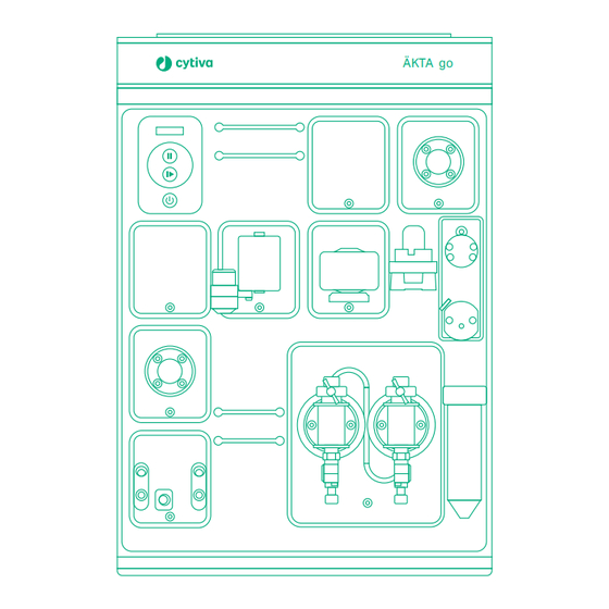
3 System description 3.1 ÄKTA go ÄKTA go Introduction This section provides an overview of the ÄKTA go instrument. Illustration of the ÄKTA go system The illustration below shows the ÄKTA go system. The computer with the UNICORN software is located on the right hand side of the instrument to make room for accesso- ries on the left hand side of the instrument. - Page 20 3 System description 3.1 ÄKTA go Illustration of the ÄKTA go instrument The illustration below shows the ÄKTA go instrument with all standard components denoted. The instrument in the illustration also has an optional column valve and a column connected. Part Function Pump...
- Page 21 3 System description 3.1 ÄKTA go Note: Control panel buttons can be locked using the UNICORN software. Part Function Display Status indicator Pause button Run/Continue button On/Off button Status indicators The display and status indicators on the instrument control panel indicate the current status of ÄKTA go.
- Page 22 3 System description 3.1 ÄKTA go State Display Description Offline Power is on, but the instrument has no communication with the UNICORN instrument server. The display toggles between Offline, the instrument IP address, and the Instrument serial number. Connecting The instrument is connecting to the UNICORN instrument server.
- Page 23 3 System description 3.1 ÄKTA go State Display Description Pause A run has been paused (pump is stopped). Hold A run has been put on hold (pump is still pumping at an unchanged flow rate). Wash A system wash or a pump wash instruction is ongoing.
- Page 24 3 System description 3.1 ÄKTA go State Display Description Power-save The instrument is in power- save mode. The status indicator is half-lit with a white light, flashing slowly. Re-program- A module is being re- ming programmed during an instru- ment configuration installa- tion.
-
Page 25: Available Modules
3 System description 3.2 Available modules Available modules Introduction The ÄKTA go instrument is delivered with standard modules installed. There is space for installation of six additional modules in the system, two inside the chassis and four connected via cables at the rear of the instrument. This section describes the standard and optional modules. - Page 26 3 System description 3.2 Available modules Optional modules The following modules can be added to the system. A maximum of six optional modules can be connected to the system. Module Description External air An air sensor used to either complete sample loading via the sensor L9‑1.5 pump, or to detect if the system has run out of buffer, depending on placement.
- Page 27 The system can be equipped with a Real-Time Unit (RTU), which must be installed by a Cytiva service representative. The RTU can be used in certain network environments to make sure the run continues if the computer is rebooted or otherwise locked due to, for example, software updates.
-
Page 28: Unicorn
Advanced features requires Evaluation Classic, avail- able from Cytiva. When working with the software modules Administration, Method Editor, System Control, and Evaluation Classic it is possible to access descriptions of the active window or software instruction by pressing the F1 key. - Page 29 3 System description 3.3 UNICORN Opening a UNICORN module Modules to open are selected at log in, but can also be opened from another module when the software is already open. In the Administration, Method Editor, or System Control modules, to open a software module, click Tools and select the applicable module.
- Page 30 Column Handling tool, Connect to Systems which contains a column dialog box where systems can be connected, and list, with parameters for Cytiva columns. With an currently connected users additional license, a are displayed. Column Logbook to keep track of user-purchased columns is also available.
- Page 31 3 System description 3.3 UNICORN Process Picture pane The most commonly used manual interactions can be executed using the Process Picture. Click on the different parts of the Process Picture pane to interact with the system. For a complete list of manual instructions, go to Manual → →Execute manual instructions.
-
Page 32: Installation
4 Installation Installation About this chapter This chapter provides the instructions necessary to enable users to install the instru- ment and the software. Read the entire Installation chapter before starting to install ÄKTA go. Note: For information how to unpack the ÄKTA go instrument and how to lift the instrument onto a laboratory bench refer to the ÄKTA go Unpacking instruc- tions. -
Page 33: Site Preparation
4 Installation 4.1 Site preparation Site preparation Introduction This section describes the site planning and the preparations necessary for the instal- lation of ÄKTA go. The performance specifications of the system can be met only if the laboratory envi- ronment fulfills the requirements stated in this chapter. In this section Section See page... -
Page 34: Delivery, Storage, And Unpacking
When you receive the delivery • Record on the receiving documents if there is any apparent damage on the delivery box. Inform your Cytiva representative of such damage. • Move the delivery box to a protected location indoors. Delivery box The ÄKTA go instruments are shipped in a delivery box with the following dimensions... - Page 35 4 Installation 4.1 Site preparation 4.1.1 Delivery, storage, and unpacking Moving the ÄKTA go instrument The instrument is heavier at the front. Do not tip the instrument when lifting. The illus- tration below shows the recommended way to lift the ÄKTA go instrument. ÄKTA go Operating Instructions 29360951 AE...
-
Page 36: Space Requirements
4 Installation 4.1 Site preparation 4.1.2 Space requirements 4.1.2 Space requirements Introduction This section describes the requirements for the laboratory bench on which the instru- ment is placed. WARNING Access to power plug. Do not block access to the power outlet and power plug. - Page 37 4 Installation 4.1 Site preparation 4.1.2 Space requirements Parameters Specifications Min. height above the laboratory bench 48 cm Space for handling of buffers and 10 cm samples Free space around the instrument to allow for 10 cm adequate ventilation Location of the computer with respect Right to instrument Dimensions and weight...
- Page 38 4 Installation 4.1 Site preparation 4.1.2 Space requirements Parameter Value Weight 27 kg Allowed weight of buffer bottles on the 10 kg top tray ÄKTA go Operating Instructions 29360951 AE...
-
Page 39: Site Environment
4 Installation 4.1 Site preparation 4.1.3 Site environment 4.1.3 Site environment Introduction This section describes the environmental requirements for installation of ÄKTA go. Environmental requirements The following general requirements must be fulfilled: • The room must have exhaust ventilation. • The instrument must not be exposed to direct sunlight. •... - Page 40 4 Installation 4.1 Site preparation 4.1.3 Site environment Heat output The heat output is listed in the table below. Component Heat output ÄKTA go instrument Typical 100 W Max 150 W Power save < 20 W For heat output of the computer, refer to the manufacturer's specifications. ÄKTA go Operating Instructions 29360951 AE...
-
Page 41: Power Requirements
WARNING Power cord. Only use power cords with approved plugs delivered or approved by Cytiva. The following table specifies the power requirements for the ÄKTA go instrument. For power requirements for the computer, refer to the manufacturer's specifications. -
Page 42: Computer Requirements
General requirements ÄKTA go instruments are controlled by UNICORN software running on an external computer. The computer is not included with the ÄKTA go instrument. A suitable computer may be ordered from Cytiva or obtained from a third party supplier. WARNING Fire hazard. -
Page 43: Required Materials
4 Installation 4.1 Site preparation 4.1.6 Required materials 4.1.6 Required materials Introduction This section describes the materials required for the installation and operation of the ÄKTA go instrument. Solutions The solutions listed in the following table are required during the installation procedure and should be provided at the installation site. -
Page 44: Hardware Installation
4 Installation 4.2 Hardware installation Hardware installation Introduction This section describes the installation procedures for ÄKTA go. In this section Section See page 4.2.1 Connect the system 4.2.2 Install waste tubing 4.2.3 Prepare the pump rinsing system 4.2.4 Start the instrument ÄKTA go Operating Instructions 29360951 AE... -
Page 45: Connect The System
Protective ground. The product must always be connected to a grounded power outlet. WARNING Power cord. Only use power cords with approved plugs delivered or approved by Cytiva. WARNING Supply voltage. Before connecting the power cord, make sure that the supply voltage at the wall outlet corresponds to the marking on the instrument. - Page 46 4 Installation 4.2 Hardware installation 4.2.1 Connect the system Connector illustration The illustration below shows where the connectors are located on the ÄKTA go instru- ment. For connectors on the computer equipment, refer to the manufacturer´s docu- mentation. Connect to power Follow the steps below to connect power to the ÄKTA go instrument and the computer.
- Page 47 4 Installation 4.2 Hardware installation 4.2.1 Connect the system Connect ÄKTA go to the computer Follow the steps below to connect the ÄKTA go to the computer. Step Action Connect a network cable to the back of the instrument. The appropriate port at the back of the instrument is indicated by this symbol: Connect the other end of the network cable to the appropriate connector on the computer.
-
Page 48: Install Waste Tubing
4 Installation 4.2 Hardware installation 4.2.2 Install waste tubing 4.2.2 Install waste tubing Introduction The table below lists the waste tubing of the instrument and where it is located. Make sure that the waste tubing is connected to the correct positions on the modules. Module Tubing connections Location of tubing... - Page 49 4 Installation 4.2 Hardware installation 4.2.2 Install waste tubing Step Action Insert the waste tubing from all installed modules in a suitable vessel. Cut the waste tubing to appropriate length. It is important that the tubing is not bent. Note: If the tubing is too short, replace it with new tubing.
-
Page 50: Prepare The Pump Rinsing System
4 Installation 4.2 Hardware installation 4.2.3 Prepare the pump rinsing system 4.2.3 Prepare the pump rinsing system Introduction The pump rinsing system protects the pump seals from damage caused by precipi- tated buffer remaining in the system. The seal prevents leakage between the pump chamber and the drive mechanism of the pump. - Page 51 4 Installation 4.2 Hardware installation 4.2.3 Prepare the pump rinsing system Step Action Unscrew and remove the rinsing solution tube from the holder. Fill the rinsing solution tube with 50 mL of 20% ethanol or aqueous buffer. Screw the rinsing solution tube back into the holder. Insert the inlet tubing into the solution in the rinsing solution tube.
- Page 52 4 Installation 4.2 Hardware installation 4.2.3 Prepare the pump rinsing system Step Action Unscrew the rinsing solution tube and fill it with 50 mL of 20% ethanol or aqueous buffer. ÄKTA go Operating Instructions 29360951 AE...
-
Page 53: Start The Instrument
4 Installation 4.2 Hardware installation 4.2.4 Start the instrument 4.2.4 Start the instrument Follow the steps below to start the instrument. Step Action Turn on the instrument by pressing the On/Off button. The instrument control panel displays a white light for approximately two seconds. -
Page 54: Software Installation
4 Installation 4.3 Software installation Software installation Introduction This section provides an overview of how to install UNICORN and adapt the software to your instrument. For more information, refer to the UNICORN Quick Installation Guide. The software should be installed by someone assigned to be a UNICORN system administrator at the site. -
Page 55: Download And Install Unicorn
4 Installation 4.3 Software installation 4.3.1 Download and Install UNICORN 4.3.1 Download and Install UNICORN UNICORN is delivered via e-Delivery. An URL to the e-Delivery and Activation ID are delivered upon ordering the ÄKTA go system. Follow the steps below to install the UNICORN software. For more information on installing UNICORN, Windows settings, and configuring the e-license, refer to the UNICORN Quick Installation Guide. -
Page 56: Download The Instrument Configuration
An instrument configuration is used to adapt UNICORN to your instrument. Follow the instructions below to import the Instrument Configuration into the UNICORN soft- ware. Step Action Go to cytiva.com. Click RELATED DOCUMENTS. Click SOFTWARE. Download the Instrument configuration software. Use the downloaded instrument configuration to define your system, see Section 4.3.3 Adapt UNICORN to your system, on page... -
Page 57: Adapt Unicorn To Your System
This is done following the steps below. Step Action Download the latest instrument configuration for ÄKTA go from cytiva.com/ aktago, see Section 4.3.2 Download the Instrument Configuration, on page Note: An instrument configuration is used to adapt UNICORN to your instrument. - Page 58 4 Installation 4.3 Software installation 4.3.3 Adapt UNICORN to your system Note: A detailed description of how to adapt UNICORN to your system, including system setup, is found in the UNICORN Administration and Technical Manual. ÄKTA go Operating Instructions 29360951 AE...
-
Page 59: Start Unicorn And Connect To System
4 Installation 4.4 Start UNICORN and connect to system Start UNICORN and connect to system Introduction This section describes how to start and log on to UNICORN, and how to connect to the system in UNICORN. Prerequisites For UNICORN to be correctly installed, the following conditions must be set: •... - Page 60 4 Installation 4.4 Start UNICORN and connect to system Step Action Click OK. Connect to system Follow the instructions to connect to the system in UNICORN. Note: The system must have been defined by the UNICORN system administrator for it to be present in the database. Step Action In the System Control module, click the Connect to Systems button.
- Page 61 4 Installation 4.4 Start UNICORN and connect to system Set up Power-save To minimize power consumption when the system is not used, there is a Power-save function in UNICORN. Follow the steps below to activate the Power-save function. Step Action In System Control click System →Settings →Advanced.
-
Page 62: Prepare The System For A Run
5 Prepare the system for a run Prepare the system for a run About this chapter This chapter gives instructions on how to prepare the ÄKTA go system for a run and what to do before the first run. In this chapter Section See page Prepare the flow path... - Page 63 5 Prepare the system for a run CAUTION Fasten bottles. Always fasten bottles to the rails at the front panel. Use appropriate holders for bottles. Shattered glass from falling bottles may cause injury. Spilled liquid may cause fire hazard and personal injury. CAUTION Max.
-
Page 64: Prepare The Flow Path
5 Prepare the system for a run 5.1 Prepare the flow path Prepare the flow path Introduction The ÄKTA go instrument, as delivered, is prepared with a default flow path. The modules in this flow path must be defined in the software, see Section 4.3.3 Adapt UNICORN to your system, on page 57. - Page 65 5 Prepare the system for a run 5.1 Prepare the flow path Part Description Part Description Outlet valve V9-Os/V9-O Mixer Injection valve V9-J Fraction collector F9-T/F9-R Column Prepare the waste tubing Make sure that the waste tubing is prepared according to the instructions in Section 4.2.2 Install waste tubing, on page Prepare the outlet tubing...
-
Page 66: Prime Inlets And Purge Pump Heads
5 Prepare the system for a run 5.2 Prime inlets and purge pump heads Prime inlets and purge pump heads Introduction Before using the pump, it is important to prime all inlets and purge the pump heads, that is, to fill the inlets and pump heads with liquid so that no air remains inside. Overview The procedure consists of the following stages: 1. - Page 67 5 Prepare the system for a run 5.2 Prime inlets and purge pump heads Step Action Connect a 25 to 30 mL syringe to the purge valve of one of the pump heads. Open the purge valve by turning it counter-clockwise one and a half turns. Draw liquid slowly into the syringe until liquid reaches the pump and the inlet tubing is filled with liquid.
- Page 68 5 Prepare the system for a run 5.2 Prime inlets and purge pump heads Step Action Result: The injection valve switches to waste position and opens inlet A. In the Process Picture pane, click Inlet Valve and select the inlet that will be used at the beginning of the run.
- Page 69 5 Prepare the system for a run 5.2 Prime inlets and purge pump heads Step Action Result: A system flow starts. Connect a 25 to 30 mL syringe to the purge valve of the left pump head. Open the purge valve by turning it counter-clockwise about one and a half turns.
- Page 70 5 Prepare the system for a run 5.2 Prime inlets and purge pump heads Step Action In the Chromatogram pane, check the pressure curve. If the pressure does not stabilize within a few minutes, there could be air left in the pump. Note: The pressure signal is considered stable if the fluctuation is no more than 5% up or down.
- Page 71 5 Prepare the system for a run 5.2 Prime inlets and purge pump heads Step Action Unstable pressure (air in the Pump) If the pressure does not stabilize within a few minutes, repeat the proce- dures to prime the inlet tubing and purge the pump. If the pressure still does not stabilize, refer to the ÄKTA go User Manual for further instructions.
-
Page 72: Performance Tests
5 Prepare the system for a run 5.3 Performance tests Performance tests Introduction This section describes how to run performance tests. Performance tests should be run before taking ÄKTA go into use, to check the functionality of the equipment. After installation of a standard equipped ÄKTA go instrument, the System test and Mixer test must be run. - Page 73 5 Prepare the system for a run 5.3 Performance tests Step Action Note: This dialog lists all tests that are available for the modules that can be installed in the ÄKTA go system. Attempting to run a test for a module that is not installed will generate an error message.
- Page 74 5 Prepare the system for a run 5.3 Performance tests Step Action Follow any instructions that are shown on the screen. Check whether the test was passed or failed in the System Performance Report. The location of the report can be found in the Method Notes panel when selecting the test in the System Performance Test tab in the System Control module.
-
Page 75: Connect A Column
5 Prepare the system for a run 5.4 Connect a column Connect a column Introduction This section describes how to connect a column to the instrument, without introducing air into the flow path. Use a column holder to secure the column. Several types of column holders are available for ÄKTA go. - Page 76 5 Prepare the system for a run 5.4 Connect a column Step Action In the Process Picture pane, select Pump, enter a low System flow (e.g. 0.2 mL/min), and click Set. Result: A system flow of 0.2 mL/min starts. Note: If your system is equipped with a column valve, make sure to start a flow in the correct position in the column valve, and connect the column to those positions.
- Page 77 5 Prepare the system for a run 5.4 Connect a column Step Action Cut a piece of tubing with appropriate length to connect the bottom of the column to the UV monitor. Remove the stop plug from the bottom of the column and connect this tubing in its place.
-
Page 78: Pressure Alarms
5 Prepare the system for a run 5.5 Pressure alarms Pressure alarms Introduction The ÄKTA go instrument is equipped with a pressure monitor directly after the pump, which measures the highest pressure in the instrument. The advanced column valve, V9-C, adds two extra pressure sensors, one directly before the column and one directly after the column. -
Page 79: Prepare For A Run At Low Temperature
5 Prepare the system for a run 5.6 Prepare for a run at low temperature Prepare for a run at low temperature Introduction The viscosity of the liquids increase as the temperature decreases. Therefore, when using the instrument in a cold room or cold cabinet, decrease the flow rate and follow the precautions listed below. -
Page 80: Run A Method
6 Run a method Run a method About this chapter This chapter gives instructions on how to run your method. In this chapter Section See page Create a method Prepare sample for loading Start a method run Monitor or interact with the run Evaluate the run Procedures after the run ÄKTA go Operating Instructions 29360951 AE... -
Page 81: Create A Method
6 Run a method 6.1 Create a method Create a method Introduction This section describes how to create a new method in the Method Editor. There are more ways to create methods in UNICORN. Refer to the UNICORN Method Manual for more information. - Page 82 6 Run a method 6.1 Create a method Step Action In the Sample Application phase, choose an appropriate sample applica- tion technique and volume. See Section 6.2 Prepare sample for loading, on page 84 for suitable sample application techniques for your sample volume.
- Page 83 6 Run a method 6.1 Create a method Tip: It is advisable to run a blank run, without sample, before running the method with sample. This makes sure that the column is clean and that the method and the system are set up properly. ÄKTA go Operating Instructions 29360951 AE...
-
Page 84: Prepare Sample For Loading
6 Run a method 6.2 Prepare sample for loading Prepare sample for loading Introduction This section describes how to prepare the sample for loading onto the column. This can be done using either a sample loop, a Superloop, or the pump. When using the pump to apply the sample, the sample inlet must first be primed. - Page 85 6 Run a method 6.2 Prepare sample for loading Prepare sample for application using the pump Follow the steps below to prepare for sample application using the pump. Step Action Make sure that the sample inlet tubing that is to be used during the run is placed in the sample container.
-
Page 86: Start A Method Run
6 Run a method 6.3 Start a method run Start a method run Introduction This section describes how to start a run using a previously created method. For further information on method creation, please refer to UNICORN Method Manual. Prerequisites Make sure that the system is correctly prepared. -
Page 87: Monitor Or Interact With The Run
6 Run a method 6.4 Monitor or interact with the run Monitor or interact with the run Introduction You can follow your ongoing method run in the System Control module. If you need to interrupt your run, use the Hold, Pause, or End buttons in the System Control toolbar. -
Page 88: Evaluate The Run
6 Run a method 6.5 Evaluate the run Evaluate the run Introduction After the run is completed, the results can be evaluated using the Evaluation module. To open the results, use the following steps. For more information on evaluating results, refer to the UNICORN user documentation. Step Action In the Evaluation module, click Result. - Page 89 6 Run a method 6.5 Evaluate the run Part Function Data from the integration is shown in a Peak table below the chromato- gram. Customize the Peak data table by clicking the settings icon on the top right of the Peak table. ÄKTA go Operating Instructions 29360951 AE...
-
Page 90: Procedures After The Run
6 Run a method 6.6 Procedures after the run Procedures after the run Introduction After the run, the instrument and column should be cleaned to prevent bacterial growth, sample contamination in the next run, and column clogging. This section describes how to clean the column using a Column CIP (Cleaning-In- Place) method, prepare the column and the instrument for storage, and how to shut down the system. - Page 91 6 Run a method 6.6 Procedures after the run Column storage If the column is not going to be used for a couple of days or longer, it must be placed in a storage solution (e.g. 20% ethanol) after a Column CIP run. Refer to the instructions for your column for specific storage instructions.
- Page 92 6 Run a method 6.6 Procedures after the run Step Action Replace the rinsing solution with 20% ethanol. See Section 4.2.3 Prepare the pump rinsing system, on page Note: If the system is equipped with a column valve, make sure all positions are cleaned with storage solution.
-
Page 93: Maintenance
This chapter provides information on how to perform basic maintenance procedures. For a complete list of maintenance procedures, refer to the ÄKTA go User Manual. WARNING All maintenance procedures inside the instrument chassis must be performed by a Cytiva service representative. In this chapter Section See page... -
Page 94: Clean The Instrument Externally
7 Maintenance 7.1 Clean the instrument externally Clean the instrument externally CAUTION Disconnect power. Always disconnect power from the instru- ment before performing any maintenance task. Maintenance interval Clean the instrument externally when required. Required material The following materials are required: •... -
Page 95: Perform System Cleaning-In-Place (Cip)
7 Maintenance 7.2 Perform system Cleaning-In-Place (CIP) Perform system Cleaning-In-Place (CIP) Introduction The System CIP method is used to clean the flow path. WARNING Explosion hazard due to leakage of flammable liquid. Make sure there is no leakage in the flow path of the instrument during the cleaning with a flammable liquid, such as ethanol. - Page 96 7 Maintenance 7.2 Perform system Cleaning-In-Place (CIP) • Syringe, 25 to 30 mL Create a System CIP method The default System CIP method comprises of phases that cleans the system with water, 1 M NaOH, 0.1 M NaCl, and buffer. Default inlets are B, C, Sample, and A, respec- tively.
- Page 97 7 Maintenance 7.2 Perform system Cleaning-In-Place (CIP) Perform a System CIP Follow the steps below to run a System CIP method. Step Action Remove the column tubing and connect tubing between the Col port on the injection valve and the UV monitor. Note: If you have a column valve, connect bypass tubing to all column positions.
- Page 98 7 Maintenance 7.2 Perform system Cleaning-In-Place (CIP) Step Action Fill a syringe with approximately 10 mL of an appropriate cleaning solution (1 M NaOH or buffer solution). Connect the syringe to injection valve port Syr, and inject the cleaning solution. Fill a syringe with distilled water.
-
Page 99: Replace Pump Rinsing Liquid
7 Maintenance 7.3 Replace pump rinsing liquid Replace pump rinsing liquid Replace pump rinsing liquid once a week if you are using 20% ethanol and daily if you are using an aqueous buffer. For instructions, see Section 4.2.3 Prepare the pump rinsing system, on page ÄKTA go Operating Instructions 29360951 AE... -
Page 100: Replace The Main Fuses
7 Maintenance 7.4 Replace the main fuses Replace the main fuses WARNING Disconnect power. Always disconnect power from the instru- ment before replacing fuses. WARNING For continued protection from fire hazard, replace only with same type and rating of fuse. WARNING If a fuse requires repeated replacement, do not continue to use the instrument. - Page 101 7 Maintenance 7.4 Replace the main fuses Step Action Use a small flat-bladed screwdriver to prise open the fuse holder cover on the power inlet. Pull the fuse holder out of the mains connector panel by hand. Remove the fuses from the fuse holder. Fit new fuses with size 5 x 20 mm and rating T4AL 250 V.
-
Page 102: Troubleshooting
8 Troubleshooting Troubleshooting About this chapter This chapter provides a list of the most commonly encountered problems that might occur when operating ÄKTA go. For a more comprehensive list and a more detailed description of the actions to take, refer to ÄKTA go User Manual. Problem Possible cause Corrective action... - Page 103 System error report When you request troubleshooting assistance from Cytiva, you should generate a System error report (system error report) and submit it to your service representa- tive. Follow the instructions below to generate a System error report.
-
Page 104: Reference Information
9 Reference information Reference information About this chapter This chapter contains reference information. In this chapter Section See page System specifications Chemical resistance specifications Recycling information Regulatory information ÄKTA go Operating Instructions 29360951 AE... -
Page 105: System Specifications
9 Reference information 9.1 System specifications System specifications Technical specifications Parameter Specification System configuration Benchtop system, external computer Flow rate range 0.01 to 25 mL/min Pressure range 0 to 5 MPa (0 to 50 bar) Control system ÄKTA go 1.0 UNICORN 7.4 or later version ÄKTA go 2.0 UNICORN 7.6 or later version ÄKTA go 3.0 UNICORN 7.6 or later version Connection between PC and instrument... -
Page 106: Chemical Resistance Specifications
Introduction This section provides detailed information about chemical resistance of the ÄKTA go instrument to some common aggressive chemicals used in liquid chromatography. For information regarding chemicals not listed in this section, contact your Cytiva repre- sentative. Note: Refer to Safety Data Sheets (SDS) for information regarding characteristics, human and environmental risks and preventive measures for chemicals used. - Page 107 9 Reference information 9.2 Chemical resistance specifications Chemical Concentration CAS no EC no Ethanol 75-08-1 200-837-3 Ethylene glycol 107-21-1 203-473-3 Ethylenediaminetetraacetic 100 mM 60-00-4 200-449-4 acid (EDTA) Glycerol 56-81-5 200-289-5 Guanidinium hydrochloride 50-01-1 200-002-3 Mercaptoethanol 20 mM 37482-11-4 253-523-3 Phosphoric acid 0.1 M 7664-38-2 231-633-2...
-
Page 108: Recycling Information
Recycling of hazardous substances The product contains hazardous substances. Detailed information is available from your Cytiva representative. Disposal of electrical components Waste electrical and electronic equipment must not be disposed of as unsorted munic- ipal waste and must be collected separately. -
Page 109: Regulatory Information
9 Reference information 9.4 Regulatory information Regulatory information Introduction This section lists the regulations and standards that apply to the product. Your system is marked or listed according to the applicable regulatory requirements for your region. Local language translations are only provided according to regulatory requirements. In this section Section See page... -
Page 110: Contact Information
Manufacturing information The table below summarizes the required manufacturing information. Requirement Information Name and address of manufacturer Cytiva Sweden AB Björkgatan 30 SE 751 84 Uppsala Sweden Telephone number of manufacturer + 46 771 400 600 ÄKTA go Operating Instructions 29360951 AE... -
Page 111: European Union And European Economic Area
9 Reference information 9.4 Regulatory information 9.4.2 European Union and European Economic Area 9.4.2 European Union and European Economic Area Introduction This section describes regulatory information for the European Union and European Economic Area that applies to the product. Conformity with EU Directives See the EU Declaration of Conformity for the directives and regulations that apply for the CE marking. -
Page 112: Great Britain
9 Reference information 9.4 Regulatory information 9.4.3 Great Britain 9.4.3 Great Britain Introduction This section describes regulatory information for Great Britain that applies to the product. Conformity with UK Regulations See the UK Declaration of Conformity for the regulations that apply for the UKCA marking. -
Page 113: Eurasian Economic Union (Евразийский Экономический Союз)
Customs Union and (or) the Eurasian Economic Union. Requirement Information Name, address and telephone See Manufacturing information number of manufacturer Importer and/or company for Cytiva RUS LLC obtaining information about 109004, Moscow importer internal city area Tagansky municipal district Stanislavsky str., 21, building 5, premises I,... - Page 114 ул. Станиславского, д. 21 стр. 5, помещ. I, ком. 24,25,29 Российская Федерация Телефон: +7 985 192 75 37 Адрес электронной почты: rucis@cytiva.com Description of symbol on the nameplate Описание символов на заводской табличке This Eurasian compliance mark indicates that the product is...
-
Page 115: North America
Note: The user is cautioned that any changes or modifications not expressly approved by Cytiva could void the user’s authority to operate the equip- ment. This equipment has been tested and found to comply with the limits for a Class A digital device, pursuant to part 15 of the FCC Rules. -
Page 116: General Regulatory Statements
9 Reference information 9.4 Regulatory information 9.4.6 General regulatory statements 9.4.6 General regulatory statements Introduction This section shows regulatory statements that are applicable to more than one geographical region. EMC emission, CISPR 11: Group 1, Class A statement NOTICE This equipment is not intended for use in residential environments and may not provide adequate protection to radio reception in such environments. -
Page 117: South Korea
9 Reference information 9.4 Regulatory information 9.4.7 South Korea 9.4.7 South Korea Introduction This section describes the regulatory information to comply with the Korean technical regulations. Compliance statement NOTICE Class A equipment (equipment for business use). This equipment has been evaluated for its suitability for use in a business environment. -
Page 118: China
9 Reference information 9.4 Regulatory information 9.4.8 China 9.4.8 China This section describes the information that applies to the product in China. 有害物质声明 (DoHS) Declaration of Hazardous Substances (DoHS) 根据 SJ/T11364-2014《电子电气产品有害物质限制使用标识要求》特提供如下 有关污染控制方面的信息。 The following product pollution control information is provided according to SJ/ T11364-2014 Marking for Restriction of Hazardous Substances caused by electrical and electronic products. - Page 119 9 Reference information 9.4 Regulatory information 9.4.8 China 电子信息产品污染控制标志说明 Explanation of Pollution Control Label 该标志表明本产品含有超过中国标准 GB/T 26572 《电子电气产品中限用物质的 限量要求 》中限量的有害物质。标志中的数字为本产品的环保使用期,表明本 产品在正常使用的条件下,有毒有害物质不会发生外泄或突变,用户使用本产 品不会对环境造成严重污染或对其人身、财产造成严重损害的期限。单位为 年。 为保证所申明的环保使用期限,应按产品手册中所规定的环境条件和方法进行 正常使用,并严格遵守产品维修手册中规定的定期维修和保养要求。 产品中的消耗件和某些零部件可能有其单独的环保使用期限标志,并且其环保 使用期限有可能比整个产品本身的环保使用期限短。应到期按产品维修程序更 换那些消耗件和零部件,以保证所申明的整个产品的环保使用期限。 本产品在使用寿命结束时不可作为普通生活垃圾处理,应被单独收集妥善处 理。 This symbol indicates the product contains hazardous materials in excess of the limits established by the Chinese standard GB/T 26572 Requirements of concentration limits for certain restricted substances in electrical and electronic products.
- Page 120 9 Reference information 9.4 Regulatory information 9.4.8 China 有害物质的名称及含量 Name and Concentration of Hazardous Substances 产品中有害物质的名称及含量 Table of Hazardous Substances’ Name and Concentration 部件名称 有害物质 Compo- Hazardous substance nent name 铅 汞 镉 六价铬 多溴联苯 多溴二苯醚 (Pb) (Hg) (Cd) (Cr(VI)) (PBB) (PBDE) 29375260...
-
Page 121: Health And Safety Declaration Form
Service Ticket #: To make the mutual protection and safety of Cytiva service personnel and our customers, all equipment and work areas must be clean and free of any hazardous contaminants before a Service Engineer starts a repair. To avoid delays in the servicing of your equipment, complete this checklist and present it to the Service Engineer upon arrival. - Page 122 To make sure the mutual protection and safety of Cytiva personnel, our customers, transportation personnel and our environment, all equipment must be clean and free of any hazardous contaminants before shipping to Cytiva. To avoid delays in the processing of your equipment, complete this checklist and include it with your return.
-
Page 123: Index
Index Index Instrument control panel, 20, 21 status indications, 21 ÄKTA go system, 105 Instrument overview, 19, 20 specifications, 105 exterior design, 19 Ambient environment, 39 instrument control panel, 20 CE, 111 Log on, 59 conformity, 111 UNICORN, 59 marking, 111 CIP, 95 system CIP, 95 Connect system units, 45... - Page 124 Index Pump piston rinsing system, 50 UKCA, 112 illustration, 50 marking, 112 prime, 50 UNICORN , 28, 59, 60 Pumps, 66 connect to system, 60 purge system pumps, 66 log on, 59 Purpose of this manual, 6 software modules, 28 start, 59 Recycling information, 108 decontamination, 108...
- Page 125 Page intentionally left blank...
- Page 126 QR code. cytiva.com Cytiva and the Drop logo are trademarks of Life Sciences IP Holdings Corp. or an affiliate doing business as Cytiva. ÄKTA, ÄKTA avant, ÄKTA go, ÄKTA pcc, ÄKTA pure, Superloop, and UNICORN are trademarks of Global Life Sciences Solutions USA LLC or an affiliate doing business as Cytiva.
Need help?
Do you have a question about the AKTA go and is the answer not in the manual?
Questions and answers