Table of Contents
Advertisement
Quick Links
51.99598-8262
MAN Truck & Bus AG
Vogelweiherstraße 33
90441 Nürnberg
oder
Postfach 44 02 58
90441 Nürnberg
MAN Industrial Diesel Engines
3st edition
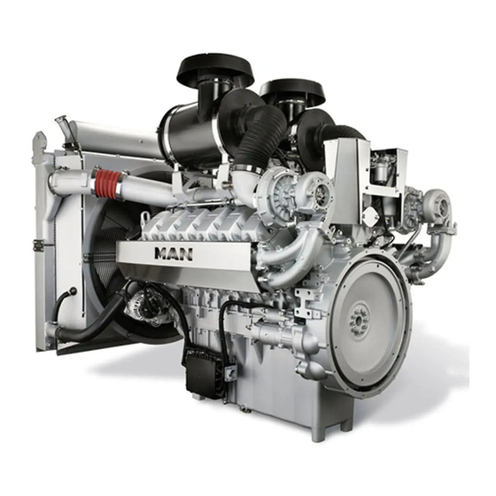
D2862 LE221
D2862 LE223
Copy deadline: 05.2015
Repair Manual
Reparaturanleitung AE6, 3. Ausgabe
MAN-Industriedieselmotoren
D2862 LE221
D2862 LE223
Printed in Germany
AE6
- Englisch -
Advertisement
Table of Contents


Need help?
Do you have a question about the D2862 LE221 and is the answer not in the manual?
Questions and answers
Selam.ben Man 2868 LE121 endüstriyel motor alacağım... Yardımcı olurmusunuz... Karel motorlu araçlar ltd sti Tural Erdoğan Tel. +905426545637
Selam.ben man 2868 LE121 endüstriyel yeni motor alacağım. Yardımcı olurmusunuz