Table of Contents
Advertisement
Quick Links
Advertisement
Table of Contents
Troubleshooting

Related Manuals for Man D 2866 LUE 605


Summary of Contents for Man D 2866 LUE 605
-
Page 3: Preface
We reserve the right to make technical modifications in the course of further development. 2003 MAN Nutzfahrzeuge Aktiengesellschaft Reprinting, copying or translation, even in the form of excerpts, is forbidden without the written permission of MAN. MAN expressly reserves all rights in accordance with the law on copyright. MTDA Technical status: 06.2003... -
Page 4: Instructions
Tighten bolts evenly to the specified torque. Fitting toric seals Use only genuine MAN toric seals. The sealing faces must be undamaged and clean. Always wet toric seals with engine oil before fitting them... -
Page 5: Table Of Contents
..........Repairing coolant pump with high-temperature and low-temperature parts D 2866 LUE 605 . - Page 6 ............Engine lubrication D 2866 LUE 605 .
-
Page 7: Engine Type Classification
The “6” indicates the number of cylinders 6 This letter stands for “charge-air cooling” (German: Ladeluftkühlung) The “U” stands for “Underfloor” The “E” stands for “fitted engine” (German: Einbaumotor) and is intended to distinguish MAN vehicle engines 602/6.. This is a factory-internal development number. - Page 8 Safety instructions General information This brief overview summarises important instructions and is structured into areas of main concern in order to impart the knowledge necessary to prevent accidents involving injury to persons, damage to the engine or other property and harm to the environment. Additional notes are included in the operator’s manual for the engine.
-
Page 9: Safety Instructions
D In the event of operational faults immediately identy the cause and rectify to prevent more serious dam- age. D Always use genuine MAN parts only. Installation of “equally” good parts from other suppliers may cause severe damage for which the workshop carrying out the work is responsible. - Page 10 Safety instructions 3. Instructions for preventing environmental damage Engine oil and filter cartridges and elements, fuel/fuel filters D Take old oil to an old oil disposal point only. D Ensure without fail that oil and Diesel fuel will not get into the sewerage system or the ground. Caution: Danger of contaminating potable water! D Treat filter elements and cartridges as special waste.
-
Page 11: General Notes On Engine Overhaul
D Inspection if installation by authorised personnel D Proper design and setting of and supply to the mixture formation system and the ignition system D Selection and quality of lubricants, gas and coolant according to publication “Fluids and lubricants for MAN Diesel Engines”... -
Page 12: Commissioning After Engine Overhaul
Commissioning after engine overhaul Pressurisation It is extremely important for internal combustion engines (following the completion of repair work, i.e. in their dry state) to be pressurised with lube oil before being recommissioned. This procedure can also be used for ascertaining damage and its causes. If engines are not pressurised, the risk of premature damage to bearing surfaces is very high because it takes a relatively long period of time for the lube oil drawn in from the oil pan via the oil pump to reach the individual bearings. - Page 13 Commissioning after engine overhaul Pressurising an engine affords the following advantages: D All engine parts are lubricated before engine startup; a lubricating film can be built up inside the bea- rings as early as after the first few rotations of the crankshaft, thereby preventing damage to the bearing races.
- Page 14 Notes ..........................................................................................................................................................................................................................................................................................................................................................................................................................................................................................................................................................................................................................................................................................................................................................................................
-
Page 15: Fault Table
The precondition for this, however, is that the experts are familiar with the Repair Manual for the engine as well as the accompanying Operating Instructions and the publication “Fuels, Lu- bricants and Coolants for MAN Diesel Engines”. -
Page 16: Troubleshooting Chart
Troubleshooting chart EDC self-diagnosis or flash code output Starter turns over engine only slowly or not at all Starter turns, engine does not start, engine does not start / difficult to start when cold Engine stalls (dies) during operation, no longer starts (starter turns), engine does not start / starts with difficulty when hot Sudden, temporary engine shut-down, engine does not reach full revs Engine only runs at idle speed, no throttle response Engine only runs at increased idle speed, no throttle response... - Page 17 Troubleshooting chart EDC self-diagnosis or flash code output Starter turns over engine only slowly or not at all Starter turns, engine does not start, engine does not start / difficult to start when cold Engine stalls (dies) during operation, no longer starts (starter turns), engine does not start / starts with difficulty when hot Sudden, temporary engine shut-down, engine does not reach full revs Engine only runs at idle speed, no throttle response Engine only runs at increased idle speed, no throttle response...
- Page 18 Line defective: Pin 23 or 41 o o o EDC control unit faulty (internal fault) x x x Incorrect EDC control unit (check MAN part number) Intermediate engine speed activated EOL programming terminated / voltage interrupt Afterrunning not completed (e.g. shut-down via EMERGENCY STOP)
- Page 19 Memoranda ..........................................................................................................................................................................................................................................................................................................................................................................................................................................................................................................................................................................................................................................................................................................................................................................................
-
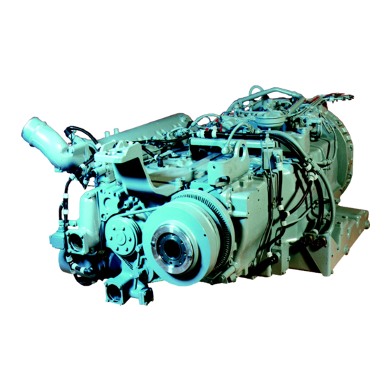
Page 20: Engine Views
Engine views Engine views... - Page 21 Engine views 1 Injection pump 2 Crankcase breather 3 Oil filter 4 Turbocharger 5 Flame-starter sheathed-element glow plug 6 Solenoid valve for flame-starter 7 Electro-hydraulic cutout (EHAB) (only D 2866 LUE 602) 8 Oil drain plugs 9 Pilot clutch 10 TDC mark 11 Water pump...
-
Page 22: Engine Lubrication Diagram
Engine lubrication diagram Schematic diagram of engine lubrication system 1 Oil cooler 11 Oil pump 2 Bore for rocker arm lubrication 12 Oil suction pipe 3 Bore for oilcooler 13 Oil suction pipe 4 Bore for injection pipe-lubrication 14 Spray nozzles for piston cooling 5 injection pump 15 Bore for main bearing lubrication 6 Bore for oil cooler... -
Page 23: Fuel System Diagram
Fuel system diagram Fuel system - Schematic diagram D 2866 LUE 602 1 Flame-starter sheathed-element glow plug 7 Hand pump 2 Soleniod valve 8 Fuel filter 3 Injection pump 9 Fuel supply from tank 4 Fuel return to tank 10 Fuel pre-filter 5 Leak fuel 11 Electro-hydraulic shut-off (EHAB) 6 Fuel delivery pump... - Page 24 Fuel system diagram Fuel system - Schematic diagram D 2866 LUE 605 1 Flame-starter sheathed-element glow plug 6 Tank 2 Solenoid valve 7 Fuel pre-filter 3 Injection pump 8 Hand pump 4 Fuel return to tank 9 Fuel Filter 5 Fuel delivery pump...
-
Page 25: Cooling System Diagram
Cooling System Diagram 1 Surge tank 6 Retarder-oil cooler 2 Positive pressure / negative pressure valve 7 Thermostat 3 Coolant filler neck 8 Water pump 4 Thermostat 9 Oil cooler 5 Radiator 10 Engine / crankcase... -
Page 26: Engine Management Diagram
Engine management schedule 1 Oil pump impeller gear 4 Injection pump drive gear 2 Oil pump drive gear 5 Idler gear 3 Crankshaft gear 6 Camshaft gear... -
Page 27: Checking And Adjusting Start Of Fuel Delivery
Checking and adjusting start of fuel delivery Checking start of delivery Fig. 1 For the purpose of checking the start-of-delivery setting, an “OT” (= TDC) mark and a scale from 10 ... 50_ before TDC are engraved on a disc Á fitted in front of the torsional vibration damper. - Page 28 Checking and adjusting start of fuel delivery Fig. 5 Remove screw plug À on governor housing. If fitted, take out blocking pin Á. Caution: If the injection pump is blocked the cam- shaft must on no account be loaded or turned because parts of the blocking pin may break off and fall into the governor.
- Page 29 Checking and adjusting start of fuel delivery 2. Sleeve ø15 Fig. 8 ø12 If a light signal transmitter is not available, good ø9 measurement results can also be achieved with a plug-in sleeve. The sleeve is to be made of aluminium or steel. Set engine to start of delivery as described above.
- Page 30 Checking and adjusting start of fuel delivery Adjusting start of delivery If the check according to method 1) or 2) should prove that the delivery start is not correct, proceed as follows: Remove timing case cover. Fig. 9 Loosen all bolts fastening the drive gear to the in- jection pump hub.
-
Page 31: Removing And Installing Injection Pump
Removing and Installing Injection Pump Removing injection pump Fig. 1 and Fig. 2 Remove the injection lines from the injection pump and from the injection nozzles. Note: The subsequent reinstallation of the injec- tion pump is rendered considerably ea- sier if before its removal the engine has been turned to start of delivery. - Page 32 Removing and Installing Injection Pump Fig. 5 Turn engine to angle for delivery start. Remove the cylinder head cover from cylinder no. 6 (flywheel end). When the valves for this cylinder overlap, the piston in cylinder no. 1 is at firing TDC. Fig.
-
Page 33: Removing And Installing Injection Nozzles
Removing and Installing Injection Nozzles Removing injection nozzles Fig. 1 Remove the injection lines from the injection pump and from the injection nozzles. Remove the fuel return lines. Fig. 2 Remove pressure screw from fuel injector using a pin spanner. Fig. - Page 34 Removing and Installing Injection Nozzles Fig. 5 (Example) The lubricant, which is available as a spray, must be applied to the inside of the pressure screw, to the threaded portion of the pressure screw and to the nozzle holder (see shaded area). Fig.
-
Page 35: Checking And Repairing Fuel Injectors
Checking and repairing fuel injectors Checking fuel injectors Fig. 1 The nozzle tester (manual test stand) is used to check the opening pressure tightness spray pattern of the injection nozzle. Use pure testing oil or pure Diesel fuel for the test. Prior to testing, clean nozzle and check it for wear, see page 34. - Page 36 Checking and repairing fuel injectors Disassembling fuel injectors Fig. 3 Insert injector assembly (the inlet orifice facing downwards) into the clamping device and hold in a vice. Remove union nut and take out nozzle body, inter- mediate washer, pressure pin, compression spring and shim.
- Page 37 Checking and repairing fuel injectors Fig. 7 Dip nozzle body and nozzle needle separately into filtered Diesel fuel and check their gliding quality. When pulled out of the nozzle body by up to a third of its length the nozzle needle must sink back to its seat under its own weight when released.
-
Page 38: Fuel Prefilter
D Screw in and tighten the hand pump plunger D Start the engine D Check the fuel prefilter for leaks Cleaning fuel pre-cleaner (D 2866 LUE 605) Strip the fuel pre-cleaner: D Remove filter housing À D Wash out filter housing À and gauze filter Á in... -
Page 39: Removing And Attaching Fuel Filter, Exchanging Filter Cartridge
Removing and attaching fuel filter, exchanging filter cartridge Changing fuel filter Only when the engine is swiched off. D Remove filter cartridge using tape wrench. D Wet seal on new filter with fuel D Screw on filter by hand D After this, bleed the fuel system D Check the filter for leaks Caution: Used fuel filters are classed as dange-... -
Page 40: Flame Starter Sheathed-Element Glow Plug,Removing And Installing
Flame starter sheathed-element glow plug, removing and installing Removing sheathed-element glow plug Fig. 1 Disconnect the electric connections from the shea- thed-element glow plug. Remove fuel line carefully. Loosen counter nut on sheathed-element glow plug and remove glow plug. Installing sheathed-element glow plug Fig. -
Page 41: Draining And Filling Coolant
The cooling system of the engine is to be filled with a mixture of drinking water from the mains and anti- freeze based on ethylene glycol and/or anticorrosion additive. See Publication “Fuels, Lubricants and Coolants for MAN Diesel Engines”. Coolant must be poured in according to the vehicle manufacturer’s filling specifications. -
Page 42: Removing And Installing Thermostats
Removing and installing thermostats D Draining off coolant, see page 39 Remove the three mounting bolts from coolant neck and take off coolant neck. Take out short-circuit inserts / thermostats. Check the function of the thermostat insert as follows. D Suspend the thermostat in a bowl of water D Heat up the water D Using a suitable thermometer, ascertain the start of opening and compare it with the setpo-... -
Page 43: Removing And Installing Engine Water Pump
Removing and installing engine water pump Removing engine water pump D Draining off coolant, see page 39 D Remove the thermostats, see page 40 Take V-belt off see page 125. Fig. 1 Remove V-belt pulley. Fig. 2 Remove the mounting bolts from water pump and take off water pump. - Page 44 Removing and installing engine water pump Installing engine water pump Fig. 3 Renew O-ring. Fit water pump with new seal. Tighten the securing bolts with the prescribed tor- que. Fig. 4 Refit V-belt pulley and coolant neck. Insert thermostat insert, see page 40. Fit and tension the V-belt see Page 126.
-
Page 45: Repairing Engine Water Pump D 2866 Lue 602
Repairing engine water pump D 2866 LUE 602 Fig. 1 1 Pump housing 2 Impeller 3 Cap 4 Mechanical seal 5 Water pump bearing 6 Hub 7 Circlip Remove water pump, see page 41 Disassembling water pump Fig. 2 Clamp the water pump in a vice (use protective jaws). - Page 46 Repairing engine water pump D 2866 LUE 602 Fig. 5 Pull impeller off the pump bearing. For this purpose four threaded bores M8 are provi- ded. Fig. 6 Align water pump housing on a suitable and stable surface. Use a suitable mandrel to press the water pump shaft together with bearing out of the housing.
- Page 47 Repairing engine water pump D 2866 LUE 602 Fig. 9 Turn water pump housing over. Press in new mechanical seal with press-fitting sleeve (special tool) until it stops. Observe installation note for seal on page 47. Note: The seal can be exchanged even without removing the water pump shaft.
- Page 48 Repairing engine water pump D 2866 LUE 602 Fig. 13 If no suitable pressing tool is available, you may use self-made special tools (see chapter “Special tools”) and proceed as follows: D Align guide ring Á with the two dowel pins on the pump housing D Insert pressing ring À...
- Page 49 Fit the mechanical seal “wet”, i.e. when fitting, coat holding sleeve à and coolant pump shaft À with a mix- ture of 50% water and 50% cleaning spirit or 40% to 50% antifreeze as per MAN 324 and water. Other antiseize agents must not be used.
-
Page 50: Repairing Coolant Pump With High-Temperature And Low-Temperature Parts D 2866 Lue 605
Repairing coolant pump with high-temperature and low-temperature parts D 2866 LUE 605 Coolant pump for three thermostats Fig. 1 and 2 1 Pump housing HT (high-temperature part) 2 Pump housing LT (low-temperature suction part) 3 Hub 4 Bolt DIN 931-M8x155, hex nut DIN 934-M8 5 Bolt DIN 933-M8x35-8.8... - Page 51 Repairing coolant pump with high-temperature and low-temperature parts D 2866 LUE 605 Fig. 5 Knock out cover by driving a suitable mandrel un- der it (Fig. 1, item 3) at notch (arrow). Fig. 6 Pull impeller off coolant pump shaft.
- Page 52 Install mechanical seal while “wet”, i.e. to install it, coat holding sleeve and water pump shaft with a mixture of either 50% water and 50% cleaning spi- rit or 40% to 50% antifreeze agent as per MAN 324 and water.
- Page 53 Repairing coolant pump with high-temperature and low-temperature parts D 2866 LUE 605 Fig. 12 Note: Brace the bearing shaft. Slowly press impeller on to bearing shaft to ensure +0,4 correct gap (0,5 Fig. 13 Press in new mechanical seal (pos.8) with press- fitting sleeve (special tool) until it stops.
- Page 54 Repairing coolant pump with high-temperature and low-temperature parts D 2866 LUE 605 Fig. 16 Note: For subsequent steps brace the bearing shaft. Press grooved ball bearing 6003 into position using special tool. Fig. 17 Press in new mechanical seal (pos.6) with press- fitting sleeve (special tool) until it stops.
- Page 55 Repairing coolant pump with high-temperature and low-temperature parts D 2866 LUE 605 Fig. 20 Fit new pump cover and press it into housing, using a suitable pressing tool. Fig. 21 If no suitable pressing tool is available, you may use self-made special tools (see chapter “Special tools”) and proceed as follows:...
- Page 56 Install mechanical seal while ”wet”, i.e. to install it, coat holding sleeve and water pump shaft with a mixture of either 50% water and 50% cleaning spirit or 40% to 50% antifreeze agent as per MAN 324 and water. Other antiseize agents must not be used.
-
Page 57: Cleaning Cooling System
In such cases, the insects, dust etc. should be removed from the honeycomb system of the radia- tor block and the radiator itself then cleaned with the cleansing agent HENKEL P3-begesol. This cleansing agent is available from MAN in 10-kg cans under Part No. 09.21002-0164. Procedure:... - Page 58 Cleaning cooling system Removal of lime deposits in the cooling system Procedure: D Drain the coolant D Fill the system with undiluted original pickling fluid (Lithsolventsäure or engine pickling fluid RB-06), see sources of supply D Let the engine run (also in normal operation) for approx. 8 hours with this filling in the cooling circuit D Drain the pickling fluid and thoroughly flush the system with tap water D If necessary, refill the circuit again with fresh pickling fluid and pickle the engine for another 8 hours D Drain the pickling fluid, fill the system with tap water, and run the engine at idle for 5 minutes to flush out...
-
Page 59: Changing The Oil Filter
Changing the oil filter Caution: Used oil and oil filters are classed as dan- gerous waste. Observe safety instructions for the pre- vention of environmental damage. Fig. 1 Open the oil drain plug on the oil filter casing and catch emerging oil in a suitable container. Danger: The oil filter casing and filter insert are filled with hot oil;... -
Page 60: Removing And Installing The Oil Cooler
Removing and installing the oil cooler Removing the oil cooler Caution: Old oil is hazardous waste. Observe safety instructions for the preven- tion of environmental damage. Fig. 1 Oper oil drain plug and use container to catch the oil that may emerge. Use a vessel of sufficient size to ensure that the oil does not overflow. - Page 61 Removing and installing the oil cooler Fig. 5 Take a new o-ring for oil cooler housing. Screw on oil cooler housing together with attached oil cooler. Fig. 6 Tighten the securing bolts with the prescribed tor- que. D Attach oil filter with new seals D Top up engine with oil D Top up coolant.
-
Page 62: Removing And Installing The Oil Pan
Removing and installing the oil pan Remove oil pan Caution: Old oil is hazardous waste. Observe safety instructions for the pre- vention of environmental damage. Fig. 1 Open oil filler neck. Remove oil drai plugs and allow the oil to drain off completely. - Page 63 Removing and installing the oil pan Fig. 5 Fitting the EHAB, crankcase breather and oil filler neck. Refit oil drain plugs with new seals. Fill up the engine oil. Check oil level. Check the oil pan for leaks.
-
Page 64: Removing And Installing / Repairing Oil Pump
Removing and installing / Repairing Oil Pump Removing oil pump Fig. 1 Remove the oil pan, see Page 60 Take off oil suction pipes. Measure backlash between oil pump drive gear and crankshaft gear and compare value with the nominal value. Replace worn gears. - Page 65 Removing and installing / Repairing Oil Pump Repairing the oil pump Fig. 5 Clamp the oil pump in a vice (use protective jaws). Remove the oil pump cover. Fig. 6 Pull the follower oil pump gear out of the housing. Check gears and pump housing for wear.
- Page 66 Fig. 10 Before installing, check whether the oil pumps runs smoothly and then fit them free of tension. Fit oil suction line with seal in a tension-free man- ner. Screw on pressure-relief valve without seal. Tighten the securing bolts with the prescribed tor- que.
-
Page 67: Removing And Installing Oil Spray Nozzle
Removing and Installing Oil Spray Nozzle Removing oil spray nozzle D Draining off oil, see page 60 D Removing the oil pan, see page 60 Fig. 1 Unscrew the oil spray nozzle valve (arrowed) and remove with the oil spray nozzle. Fig. - Page 68 Memoranda ..........................................................................................................................................................................................................................................................................................................................................................................................................................................................................................................................................................................................................................................................................................................................................................................................
-
Page 69: Removing And Fitting Vibration Damper, Replacing Front Crankshaft Gasket
Removing and fitting vibration damper, replacing front crankshaft gasket Removing pilot clutch Note: Match-mark the parts and remove them. Fig. 1 D Remove bolts À and take off washer  D Disconnect propshaft from clutch and pull it off D Remove inner bolts Á and lift out clutch. The driver flange remains on the engine Strip and check pilot clutch;... - Page 70 Removing and fitting vibration damper, replacing front crankshaft gasket Replacing front crankshaft gasket Fig. 3 Loosen the securing screws of the cover. Fig. 4 Remove the cover. Only replace the front crankshaft gasket as a com- plete unit, i.e. replace the bearing race and the radial shaft sealing ring.
- Page 71 Removing and fitting vibration damper, replacing front crankshaft gasket Fig. 7 Note: The engine is not delivered with the thrust ring as a series feature. The spare crankshaft seal also contains the thrust ring. A special too is required to fit the bearing race. Clean the inside of the bearing race and tail shaft.
- Page 72 Removing and fitting vibration damper, replacing front crankshaft gasket Fitting vibration damper Fig. 11 Position vibration damper with driver flange; note the position of the scale disc relative to the cranks- haft as you do so! Tighten the securing bolts with the prescribed tor- que.
- Page 73 Removing and fitting vibration damper, replacing front crankshaft gasket Fitting pilot clutch Fig. 14 Before assembly clean all clutch parts, see page 127. Push pre-assembled clutch on to driver flange and fasten it with interior bolts Á, 69 Nm. Connect propshaft to clutch again and fit washer  with bolts À, 25 Nm.
-
Page 74: Removing And Installing Flywheel, Replacing Starter Gear Ring
Removing and installing flywheel, replacing starter gear ring Removing flywheel Fig. 1 Release the mounting bolts, securing the engine against rotating if necessary. Fig. 2 Unscrew two bolts opposite one another and re- place with two guide mandrels (special tool). Remove all the bolts. - Page 75 Removing and installing flywheel, replacing starter gear ring Replacing starter gear ring Fig. 5 Remove the flywheel. Drill the starter motor toothed wheel and break with a chisel. Caution: In doing so, do not damage the flywheel. Fig. 6 Note: As the maximum axial run-out of the starter motor toothed wheel must not be exceeded, the axial run-out of the flyw-...
-
Page 76: Removing And Installing Crankshaft Seal (Flywheel End)
Removing and installing crankshaft seal (flywheel end) Removing crankshaft seal Fig. 1 Remove flywheel, see page 72. Use special tool (Fig. 2) or a screwdriver to prise out seal. Fig. 2 Special tool for prising out crankshaft seal. Installing crankshaft seal Fig. -
Page 77: Exchanging Bearing Race
Pull off the bearing race to be exchanged using a puller (special tool). Fig. 2 Insert the new bearing race into the pressing man- drel (special tool) so that for the subsequent as- sembly the internally chamfered side faces the fly- wheel. -
Page 78: Crankshaft Seals
Crankshaft seals General remarks on crankshaft seals As a matter of fundamental principle only radial shaft seals made of polytetrafluor ethylene (PTFE), trade name Teflon, are used. PTFE seals can be easily distinguished from the former elastomer seals by their considerably wider and flat sealing lip which is no longer pre-loaded by means of a tubular spring. -
Page 79: Removing And Installing Intake Manifold
Removing and installing intake manifold Note: When working on the air intake system, ensure meticulous cleanliness to prevent penetration of dirt and foreign bodies. Removing intake manifold Fig. 1 Disconnect electric cables to boost pressure sen- sor, to sheathed-element flame glow plug, to sole- noid valve and to temperature sensor. -
Page 80: Removing And Installing Exhaust Manifold
Before unscrewing all securing bolts, if appropriate replace 2 bolts by stud bolts as guides. The stud bolts with thread M10 have been produ- ced by MAN. The exhaust-gas pipe can be removed with the exhaust manifold attached. Remove the heat shields. -
Page 81: Turbocharger, Troubleshooting
Turbocharger, troubleshooting Before replacing the turbocharger, perform the following checks It is frequently the case that with excessive engine oil consumption, low power or abnormal intake and/or exhaust noise the turbocharger is replaced. When the allegedly defective part is then checked by the manufacturer, it is often determined that the char- ger is OK. - Page 82 Under no circumstances should cleaner be sprayed in while the engine is running ineffective danger of accident! In problem cases, use oil types that are less likely to lead to compressor carbonisation (see publication “Fuels, Lubricants and Coolants for MAN Diesel Engines”).
-
Page 83: Checking Charge-Air Pressure
Extreme operating conditions (full-load operation and high air temperature) and the use of unsuitable en- gine oils (see also publication “Fuels, Lubricants and Coolants for MAN Diesel Engines”) may give rise to deposits on the compressor and in the intercooler, resulting in a reduction in boost pressure. -
Page 84: Removing And Installing The Turbocharger
Removing and installing the turbocharger Removeing turbocharger Fig. 1 Detach bleed pipe leading to cylinder head cover of cylinder 6 À and oil return pipe Á from turbo- charger. Fig. 2 Then detach the pipe to the crankcase breather  and the oil pressure pipe Ã. - Page 85 Removing and installing the turbocharger Fig. 5 Detach flange either direct at turbocharger or at turbocharger flange. Take off turbocharger. Note: When placing the turbocharger to one side, ensure extreme cleanliness to pre- vent penetration of dirt and foreign bo- dies.
-
Page 86: Measuring The Axial / Radial Clearance Or The Turbocharger Shaft
Measuring the axial / radial clearance or the turbocharger shaft D Removing the turbocharger, see page 82 D Mark turbine housing relative to the bearing housing and remove turbine housing D Removing turbine housing Axial clearance Fig. 1 Apply dial gauge holder and dial gauge under pre- load to shaft end face of the turbine wheel as shown. -
Page 87: Removing And Installing Cylinder Head
Removing and installing cylinder head Removing the rocker arms and push rods Fig. 1 Take off the cylinder head covers. Caution: Residual amounts of oil may emerge du- ring this operation. Used oil is dangerous waste. Observe safety regulations to prevent da- mage to the environment. - Page 88 Removing and installing cylinder head Fig. 5 Take off cylinder head and cylinder head gasket. Check whether cylinder head sealing face and cyl- inder block are plane using a straight edge. Non-plane cylinder heads can be remilled 1 mm. Notice specified projection of injection nozzles and valve recess.
- Page 89 Removing and installing cylinder head Figs. 9 and 10 Tighten bolts by angle. Observe tightening sequence, the specified tighte- ning method, the instructions and notes concerning the cylinder head bolts. Note: To avoid any distortion between cylinder heads and exhaust manifolds, we recom- mend proceeding as follows: D Place cylinder head gaskets and cylin- der heads in position...
- Page 90 Removing and installing cylinder head General notes The sealing effect of the cylinder head gasket largely depends on whether the required initial tension for the cylinder head bolts is reached and maintained. Use calibrated torque wrenches to tighten the cylinder head bolts. When the specified final torque is applied it must be maintained for at least 5 seconds.
-
Page 91: Setting Valve Claerance
Setting valve claerance Adjust the valves only when engine is cold (max. coolant temperature 50°C). Fig. 1 Remove cylinder head cover. Caution: Residual amounts of oil may emerge du- ring this operation. Used oil is dangerous waste. Observe safety regulations to prevent da- mage to the environment. -
Page 92: Disassembling And Assembling Rocker Arm Mechanism
Disassembling and Assembling Rocker Arm Mechanism Fig. 1 Removing the rocker arm mechanism, see page 85 Disengage securing ring. Fig. 2 Remove rocker arm from rocker shaft. Note: If the rocker arm bearing bushes need to be replaced, new or exchange rocker arms ready for fitting are to be used. -
Page 93: Removing And Installing Valves
Removing and installing valves Removing valves Remove rocker arms. Take off cylinder head, see page 85. Fig. 1 Note: Valve spring and valve spring retainer can also be replaced with the cylinder head installed. For this purpose the relevant piston must be at TDC, and the valve assembly lever is required. - Page 94 Removing and installing valves Installing valves Fig. 5 Note: Minor damage to the valve seat can be eliminated by lapping using valve lapping paste. New valves must always be lapped until an even valve seat has been achieved. Machine valve seat insert if necessary. Turn cylinder head over and insert valve spring washers.
- Page 95 Removing and installing valves Fig. 9 Screw valve assembly lever on to cylinder head. Insert the valve spring washers. Insert discs and valve springs. The word “TOP” facing upwards, the tight coils facing downwards. Replace damaged or weak springs. Fig. 10 Compress the valve springs using assembly lever and insert the valve cone pieces.
-
Page 96: Removing And Installing Valve Guides
Removing and installing valve guides D Removing and installing cylinder head, see page 85 D Removing and installing valves, see page 91 Fig. 1 Press valve guide out of the combustion chamber side using pressing mandrel (special tool). Oil new valve guide and drive / press it into the cylinder head using pressing mandrel and spacer sleeve (special tool). -
Page 97: Replacing Valve Seat Insert
Replacing valve seat insert Removing valve seat insert Note: If the valve seat inserts have to be changed it is necessary to change the valve guides too, as otherwise exact refacing of the valve seat inserts after the replacement cannot be guaranteed. For these reasons previously mentioned the tool for removing and installing valve guides and valve seat inserts was also designed in such a way that if this tool is used valve seat inserts can be replaced only together with the valve guides, i.e. - Page 98 Replacing valve seat insert Installing valve seat insert Fig. 4 Cool new valve seat insert down to approx. -200°C and insert it into the cylinder head (at an ambient temperature of approx. 20°C). Carry out check by driving it in until the stop is re- ached using pressing tool.
-
Page 99: Reworking Valve Seat
Reworking valve seat Reworking valve seat (with Mira precision valve seat machining device) Fig. 1 1 Feed nut with mm scale 2 Guide ball 3 Jaccard lever 4 Lubricating nipple 5 Rotary head 6 Hex socket screw 7 Tool 8 Guide mandrel 9 Driving crank 10 Toggle switch 11 Handle... - Page 100 Reworking valve seat Fig. 4 Release Jaccard lever, place magnetic flange flush on the clamping plate and set the height so that the tool does not contact the valve seat. Set toggle switch to position 1. Tighten the Jaccard lever. Fig.
- Page 101 Reworking valve seat Fig. 8 Note: When dressing the valve seat inserts, remove as little material as possible from the seat face. The valve retrusion is to be used as ref- erence value. If the cylinder head interface is to be machined (max.
-
Page 102: Refacing Valves
Refacing valves Fig. 1 Apply abrasive paste to tapered area on the valve seat. Oil valve guide and insert valve. Fig. 2 Use valve refacer to reface valve seat by applying moderate axial pressure and describing a turning motion. Caution: Keep valve stem and valve guide free of abrasive paste. -
Page 103: Checking Compression Pressure
Checking compression pressure Fig. 1 D Check valve clearance and adjust, if necessary, see page 89 D Let engine run until coolant temperature re- aches approx. 60-80°C D Remove all fuel injectors, see page 31 D For compression guideline values, see publica- tion “Service Data”... -
Page 104: Removing And Installing The Gear Case
Removing and installing the gear case Removing the gear case D Removing the starter motor, see page 124 D Removing flywheel, see page 72 Fig. 1 Remove pipes. The timing case is bolted to the oil pan at the bot- tom. -
Page 105: Removing And Installing The Camshaft, Replacing Camshaft Bearings
Removing and installing the camshaft, replacing camshaft bearings Removing the camshaft D Draining off coolant, see page 39 D Removing the oil pan, see page 60 D Removing the starter motor, see page 124 D Removing the flywheel and timing case, see page 102 D Removing the rocker arm mechanisms and tappet push rods, see page 85 Note: When removing the camshaft, the engine must be turned by 180_. - Page 106 Removing and installing the camshaft, replacing camshaft bearings Fitting the camshaft Fig. 4 Oil and insert the valve tappets. Oil the camshaft bearing bushings. Oil the camshaft and insert carefully. Caution: Do not damage the bearings. Fig. 5 In doing so, note the marking of the crankshaft and camshaft gear wheel.
-
Page 107: Checking The Valve Timing
Checking the valve timing Note: Unsynchronised valve timing can cause severe engine damage. For this reason, following engine faults that can cause twisting of the shrunk-on camshaft toothed wheel, the correct sea- ting must be checked by checking the valve timing. This check is also recommended after the camshaft is fitted. -
Page 108: Removing And Installing The Crankshaft
Removing and installing the crankshaft Removing the crankshaft D 2866 LUE 602 D Removing the oil pan and oil pump, see page 62 D Removing the gear case, see page 102 D Remove front cover for sealing crankshaft and cylinder heads Fig. - Page 109 Removing and installing the crankshaft Check the spread of the bearing bushes Fig. 5 Place the bearing bushes together on a level sur- face. Measure and note down dimensions “A” and “B”. Spread dimension = A - B Install the crankshaft Fig.
- Page 110 Removing and installing the crankshaft Checking axial clearance Fig. 9 Note: The crankshaft axial clearance is deter- mined by the centre crankshaft bearing (thrust bearing). D Fit dial gauge holder with dial gauge to crank- case D Apply the tip of the dial gauge to the crankshaft D Move the crankshaft back and forth in axial di- rection and read off the clearance from the dial gauge...
- Page 111 Removing and installing the crankshaft Removing the crankshaft D 2866 LUE 605 D Removing the oil pan and oil pump, see page 62 D Removing the gear case, see page 102 D Remove front cover for sealing crankshaft and cylinder heads Fig.
- Page 112 Removing and installing the crankshaft Check the spread of the bearing bushes Fig. 5 Place the bearing bushes together on a level sur- face. Measure and note down dimensions “A” and “B”. Spread dimension = A - B Install the crankshaft Fig.
- Page 113 Removing and installing the crankshaft Checking axial clearance Fig. 9 Note: The crankshaft axial clearance is deter- mined by the centre crankshaft bearing (thrust bearing). D Fit the dial gauge bracket with dial gauge to the crankcase D Apply the tip of the dial gauge to the crankshaft D Move the crankshaft back and forth in axial di- rection and read off the clearance from the dial gauge...
-
Page 114: Removing And Installing Pistons With Conrods
Removing and installing pistons with conrods Removing piston with connecting rod D Remove oil pan and oil suction pipe, see Page 62 D Removing cylinder heads, see page 85 Fig. 1 Loosen and remove conrod bearing cover bolts. Fig. 2 Remove conrod bearing covers with bearing bus- hes;... - Page 115 Removing and installing pistons with conrods Installing piston with connecting rod Note: If the pistons have to be replaced, it must be determined whether oversize pistons were fitted by measuring the pistons or reading off the dimension on the piston crown.
- Page 116 Removing and installing pistons with conrods Fig. 9 Put connecting rod bearing caps in place. Caution: The numbers on the conrod bearing cap and the conrod big end must be on one side. Fig. 10 Screw in the conrod bolts and tighten them in sta- ges to the prescribed value.
-
Page 117: Removing Pistons From Conrod And Fitting, Checking - Replacing Conrod
Removing pistons from conrod and fitting, checking - replacing conrod Removing pistons from conrod and fit- ting Fig. 1 Remove pistons with conrods Fit conrod in a vice, use protective jaws. Disengage piston pin fastening. Fig. 2 Press out piston pins; in doing so, hold the piston. Remove piston and place to one side. - Page 118 Removing pistons from conrod and fitting, checking - replacing conrod Fig. 5 Clean conrod. Check for externally visible damage; if necessary, scrap damaged rods. Check parallel location of conrod and twisting of piston pin eye to bearing bush bore hole. In the case of deviations beyond the tolerance range, replace conrod.
-
Page 119: Removing And Installing / Replacing Piston Rings
Removing and installing / replacing piston rings Piston ring arrangement Fig. 1 1 Compression ring (keystone ring) 2 Compression ring (taper-face ring) 3 Oil control ring (bevelled ring) Removing piston rings Fig. 2 Remove the piston and conrod. Clamp the conrod in a vice, use protective jaws. Adjust the piston ring pliers to the piston diameter. - Page 120 Removing and installing / replacing piston rings Fitting piston rings Fig. 5 Use the piston ring pliers to engage the piston rings in the relevant piston ring groove (TOP facing upwards). Checking piston ring axial clearance Fig. 6 Determine the piston ring clearance in each piston ring groove at various points using a feeler gauge.
-
Page 121: Replacing Cylinder Liners
Replacing cylinder liners Removing cylinder liners Note: Observe oversizes for cylinder liner out- side diameters and collar heights (see ”Service Data”). D Remove cylinder head, see Page 85 D Remove piston, see Page 112 Fig. 1 Special tool for removing the cylinder liners Fig. - Page 122 Replacing cylinder liners Fig. 5 Deposit cylinder liner upright. Number cylinder li- ners in order of installation. Take off O-rings. Fig. 6 Remove O-rings from the crankcase. Clean seat for cylinder liners in the crankcase.
- Page 123 Replacing cylinder liners Checking cylinder liner protrusion Fig. 7 Clean basic bore and cylinder liner. Insert cylinder liner without O-rings into crank- case, observing the marking (ensure that it is iden- tical with the position prior to removal). Measure cylinder liner protrusion at at least four different points, using gauge holder and gauge.
- Page 124 Replacing cylinder liners Installing cylinder liners Fig. 9 Insert dry new O-rings for the lower seal (144x4) into the crankcase. Insert new O-rings for the upper seal (138x2) into the grooves on the cylinder liner. Do not overstretch the O-rings. Note: No grease or sealing agents of any kind must be used for installing cylinder liners...
-
Page 125: Measuring Piston Protrusion
Measuring piston protrusion Measuring piston protrusion Fig. 1 Remove the cylinder heads. Turn the piston to be measured to TDC. Apply the dial gauge holder with dial gauge to the crankcase sealing face. Set the dial gauge to -0-. Fig. 2 Carefully slew dial gauge holder round, lifting the dial gauge tip as you do so. -
Page 126: Removing And Installing The Starter Motor
Removing and installing the starter motor Fig. 1 Disconnect the negative cable from the battery or, if present, switch off the main battery switch. Disconnect the negative cable from the battery or, if present, switch off the main battery switch. Disconnect connecting cable at Terminal 31 (nega- tive electrode, thick cable), connecting cable Ter- minal 30 (positive electrode, thick cable) and Ter-... -
Page 127: V-Belts
V-belts Checking condition Fig. 1 D Check V-belts for cracks, oil, overheating and wear D Change demaged V-belts Checking tension Fig. 2 Use a V-belt tension tester to check V-belt tension. D Lower indicator arm À into the scale Fig. 3 D Apply tester to belt at a point midway between two pulleys so that edge of contact surface Á... - Page 128 V-belts Tensioning and changing V-belts Fig. 5 D Loosen securing bolts À. D Remove lock-nut Á D Adjust nut  until V-belt have correct tension D Retighten the lock nut and mounting bolts To replace the V-belts loosen lock-nut  and swing alternator inwards.
-
Page 129: Pilot Clutch D 2866 Lue 602
Pilot clutch D 2866 LUE 602 Dismantle pilot clutch Removing pilot clutch, see page 67 Remove external bolts À. Clutch can be dismantled into its individual parts. Clean pilot cluntch Before assembly clean all clutch parts. No petrol, kerosene or oil may be used on rubber. If there is little contamination, i.e. - Page 130 Pilot clutch Wear limits for the friction disk and friction ring above which it is advisable to replace these components Type 005 010 020 030 035 040 045 050 055 060 065 070 075 080 085 090 Thickness Permissi- ble wear Caution: All front-mounted clutches are balanced with a balance quality of Q = 6.3! If running after repairs is not smooth the clutch must be rebalanced with the limits contained in...
- Page 131 Pilot clutch D 2866 LUE 602 Friction ring wear If the wear limits of the friction ring at the propshaft are exceeded vibrations in the entire unit may arise- Service times or kilometrages when a wear check measurement must be carried out. To this end the relative movement between the clutch housing and the hub or the connected propshaft flange is measu- red with a measuring test gauge.
- Page 132 Pilot clutch Assemble pilot clutch When assembling the clutch the bolt tightening torques must be observed. Place friction disk Á and friction ring à in the flange plate Å (if re-utilised the friction disk and the friction ring should be inserted dry). Push on hub Â...
-
Page 133: Service Data
Service Data... -
Page 134: Engine
Specifications Engine Design ..........in-line, underfloor Mode of operation . -
Page 135: Crankcase
Dimensions Service Data imit values Crankcase standard size: 153.90-153,94 mm for cylinder liners with 0,5 und 1,0 mm larger outside Ø: 154,40-154,44 mm Ø standard size: Ø 145,80-145,84 mm for cylinder liners with 0,5 mm larger outside Ø: 146,30-146,34 mm for cylinder liners with 1,0 mm larger outside Ø: 146,80-146,84 mm... -
Page 136: Crankshaft
Dimensions Service Data Limiting values Crankshaft Crankshaft, front (opposite side to flywheel) 99,985-100,020 mm standard size: 89,98-90,00 mm undersize -0,25: 89,73-89,75 mm undersize -0,50: 89,48-89,50 mm undersize -0,75: 89,23-89,25 mm undersize -1,00: 88,98-89,00 mm standard size: 103,98-104,00 mm undersize -0,25: 103,73-103,75 mm undersize -0,50: 103,48-103,50 mm undersize -0,75: 103,23-103,25 mm undersize -1,00: 102,98-103,00 mm... - Page 137 Dimensions Service Data Limiting values Main bearing Data for wall thickness and bearing inner diameter also apply to the align- ment bearing standard size: 3,455-3,467 mm undersize -0,25: 3,580-3,592 mm undersize -0,50: 3,705-3,717 mm undersize -0,75: 3,830-3,842 mm undersize -1,00: 3,955-3,967 mm Bearing bore in installed condition: standard size: 104,066-104,112 mm...
-
Page 138: Flywheel And Starter Motor Gear Ring
Dimensions Service Data Limiting values Flywheel and starter motor gear ring Ø Flywheel: 432,490-432,645 mm Starter gear ring, inside diameter: 432,000-432,155 mm Interference: 0,335-0,645 mm Installation temperature: 200-230_C Ø Ø m = 65,1 kg (with starter gear) J = 2,412 kgm Number of teeth: Z = 160, Module 3 Matching gear: Starter pinion: number of teeth: (Z = 9) -
Page 139: Conrods
Dimensions Service Data imit values Conrods 46,055-46,065 mm Conrods which are discoloured and tar- nished at the big end must not be re-in- stalled. Bearing bore in directions 1, 2 and 3 and in planes a and b: 90,075-90,120 mm 8 mm 8 mm Pre-conditions:... -
Page 140: Pistons
Dimensions Service Data Limit values Pistons Compression height: 89,70-89,75 mm 0,2 mm: 89,50-89,55 mm 0,4 mm: 89,30-89,35 mm 0,6 mm: 89.10-89,15 mm Piston protrusion above crankcase: 0,013-0,331 mm Ø 46,008-46,016 mm Piston bolt diameter: 45,994-46,000 mm Ø 127,840-127,870 mm Piston weight difference per set in an engine: max. -
Page 141: Cylinder Head
Dimensions Service Data Limiting values Cylinder head Ø 12,000-12,018 mm Ø Wear limit: half the height of the valve guide: 12,05 mm ö Intake valve ö = 60_ Exhaust valve b = 45_ Ø Valve guide bore in cylinder head: 18,000-18,018 mm Ø... - Page 142 Dimensions Service Data Limiting values Cylinder-head bolts Length: With each tightening, the bolts are deliberately stressed beyond the stretch limit and each tightening thus ex- tends their length permanently. When the max. length has been reached, the bolt may no longer be used. Angle of rotation symbol 51.90490-0022: new: 167,5-168 mm, max.
-
Page 143: Valve Gear
Dimensions Service Data Limiting values Valve gear Rocker arm bearing pedestal 24,967-24,980 mm Ø Rocker arms Rocker arm radial clearance: 0,025-0,054 mm Wear limit: 0,08 mm 25.005-25.021 mm Camshaft Replace if there are traces of wear Camshaft axial clearance: 0,20-0,90 mm Wear limit: 1.5 mm 69.91-69.94 mm Backlash:... - Page 144 Dimensions Service Data Limiting values Valve tappet Bore in crankcase: 20,000-20,021 mm Ø 19.944-19.965 mm Valve clearance set when engine is cold Intake valve: 0,5 mm Exhaust valve: 0,5 mm Valve timing 1 = engine direction of turn 2 = intake valve opens 23° before TDC 3 = exhaust valve closes 30°...
-
Page 145: Engine Lubrication D 2866 Lue 602
Dimensions Service Data imit values Engine lubrication D 2866 LUE 602 Valve opening pressures Bypass valve for oil filter 1,8-2,6 bar Overpressure valve on the oil pump 9-10 bar Pressure valve of the oil injection nozzles Opening pressure 1,4-1,6 bar Pressure at max. -
Page 146: Engine Lubrication D 2866 Lue 605
Dimensions Service Data Limiting values Engine lubrication D 2866 LUE 605 Valve opening pressures Bypass valve for oil filter 1,8-2,6 bar Overpressure valve on the oil pump 9-10 bar Pressure valve of the oil injection nozzles Opening pressure 1,4-1,6 bar Pressure at max. -
Page 147: Engine Coolant Pump D 2866 Lue 602
Bore in hub / belt pulley: 25,007-25,020 mm (Ø 25 G6) Ø of bearing shaft: 25,048-25,061 mm Interference: 0,028-0,054 mm Coolant pump with high-temperature and low-temperature parts D 2866 LUE 605 gap: 0,7-0,8 mm Ø impeller: 120 mm Bearing seat in housing: Ø 61,976-61,995 mm Ø... -
Page 148: Turbocharger S3A - 91H39Gavm- 1.40Cf6
Abmessungen Service Daten Grenzwerte Turbocharger S3A - 91H39GAVM- 1.40CF6 Axial clearance Max. axial clearance: max. 0,16 mm Radial clearance Max. radial clearance: 0,64 mm... -
Page 149: Fuel System
Injectors: KDEL 82 P 7 Injection pump In-line injection pump with electromagne- tic fuel volume regulator Governor: Electronic Diesel Control (EDC) Type: M(S)5 Start of delivery Model crank angle before TDC D 2866 LUE 602 14°$1° D 2866 LUE 605 13°$1°... -
Page 150: Torque Guide Values
Torque guide values Note: All screw connections whose purpose is not stated in the following table are to be tightened in accordance with the guide values in our company standard M 3059 (see page 150). Fit the bolts slightly oiled! Screw plugs DIN 908 M14x1.5, M16x1.5... - Page 151 Torque guide values Lubrication Oil pump to crankcase M8, 8.8 ..........22 Nm Cover, oil pump M8, 8.8 .
- Page 152 Torque guide values Installation tightening torques according to company standard M 3059 Bolts / nuts with external or internal hexagon, head without collar or flange Thread size Property classes / tightening torques in Nm x pitch for 8.8 / 8 for 10.9 / 10 for 12.9 / 12 13,0...
-
Page 153: Cylinder-Head Bolts
Torque guide values Cylinder-head bolts General notes The engine can be equipped with the following cylinder-head bolts: D Rotation angle cylinder-head bolts with hexagon head, WAF 17 D Rotation angle cylinder-head bolts with Torx head Torx WAF E20 Bolts to be fitted on repair: Hexagon bolts can be replaced by Torx bolts if all the bolts of an engine are replaced. - Page 154 Torque guide values Tightening the cylinder-head bolts on a new engine Engine cold or warm) The cylinder heads are fitted with cylinder-head bolts for rotation angle tightening. On new engi- Erster Nachzug der Zylinder- nes, the cylinder-head bolts are retightened at kopfschrauben erledigt the factory after running in and marked by the sticker “First retightening of cylinder-head...
- Page 155 Torque guide values Tightening the cylinder-head bolts following a repair (engine cold) Before inserting the cylinder-head bolts, apply Intake side / injection nozzle engine oil to the thread (not the threaded hole) and coat the seating surface of the bolt head with installation paste “Optimoly White T”.
- Page 156 Torque guide values Reuse of used cylinder-head bolts Check Before used cylinder-head bolts are reused, they must be checked as follows: Length With each tightening, the bolts are deliberately stressed beyond the stretch limit and each tighte- L = shaft length ning thus extends their length permanently.
- Page 157 Special tools...
-
Page 158: Special Tools
Special tools... - Page 159 Special tools Fig. no. Designation Item code Test connection for compression recorder 80.99607-0002 V-belt tension indicator 81.66814-6001 Valve gauge 80.99607-0076 Valve setting key 80.99603-6007 Spanner for nuts on injection lines (17 mm) 80.99603-0025 Socket spanner set for fuel injector 4-groove 80.99603-0049 4-groove with fixing screw 80.99603-0121...
- Page 160 Special tools 12.2 12.1 14.1 15.6 15.7 15.4 15.3 15.1 15.3 15.5 15.1 15.2 18.1...
- Page 161 Special tools Fig. no. Designation Item code Stripping device for v-belt pulley of the water pump 80.99601-0037 Press-in mandrel for cassette sealing in conjunction with handle 14.1 80.99617-0091 Drift for sealing ring in the gear case consisting of: 12.1 Guide bush 80.99604-0068 12.2 Press plate in conjunction with handle 14.1...
- Page 162 Special tools 19.1 19.2 20.1 20.2 25.1 25.2 27.1 27.2...
- Page 163 Special tools Fig. no. Designation Item code Sleeves for valve-stem sealing 19.1 Guide sleeve for valve shaft sealing ring 80.99616-0004 19.2 Press-in sleeve for valve shaft sealing ring 80.99604-0005 Pressing tool for valve guide 20.1 Press mandrel for valve guide 80.99617-0013 20.2 Press rings in conjunction with 20.1...
- Page 164 Special tools 32.2 32.1...
- Page 165 Special tools Fig. no. Designation Item code Dial gauge bracket 90.99605-0172 Valve fitting lever 80.99606-0031 Compression recorder 10-40 bar 80.99605-0164 32.1 Tachograph disc 100 pcs 80.99605-0165 32.2 Angle adapter 81.98110-0099...
- Page 166 Special tools Fig. no. Designation Item code Measuring combination, consisting of: (1) Dial gauge 08.71000-1205 (2) Tracing pin for dial gauge 80.99605-0197 (3) Dial gauge bracket 80.99605-0179 (4) Seating pin 80.99605-0180 (5) Dial gauge bracket 80.99605-6006 (6) Dial gauge bracket 80.99605-0172 Press-on measuring plate 80.99605-0195...
- Page 167 Special tools Pressing mandel for cap, dia Ø 50,1 mm Pressing mandel for cap, dia Ø 62,1 mm...
- Page 168 Special tools Special tools for water pump repair for local manufacture (Material: steel as available) Support ring for pressing out the water pump bearing Ø 68 Ø 56...
- Page 169 Special tools Pressing ring for coolant pump cover Ø 153,8 - 154,2 Ø 137 Support ring for pressing out the water pump cover Ø 134 Ø 168...
- Page 170 Notes ..........................................................................................................................................................................................................................................................................................................................................................................................................................................................................................................................................................................................................................................................................................................................................................................................
- Page 171 Index Axial clearence ......Dismantling the oil pump ....Drain oil .
- Page 172 ......105, 142 D 2866 LUE 605 ..... .
Need help?
Do you have a question about the D 2866 LUE 605 and is the answer not in the manual?
Questions and answers