Dräger Infinity M300 Series Instructions For Use Manual
Hide thumbs
Also See for Infinity M300 Series:
- Supplemental manual (46 pages) ,
- Supplement manual (58 pages)

Subscribe to Our Youtube Channel
Related Manuals for Dräger Infinity M300 Series


Summary of Contents for Dräger Infinity M300 Series
- Page 1 Instructions for use Infinity ® M300 and M300+ Series Infinity ® M300 and M300+ Series WARNING To properly use this medical device, Software VG3.0 read and comply with these instructions for use.
- Page 3 Typographical conventions 1 Consecutive numbers indicate steps of action, with the numbering restarting with “1” for each new se- quence of actions. Bullet points indicate individual actions or different options for action. – Dashes indicate the listing of data, options, or objects. (A) Letters in parentheses refer to elements in the related illustration.
-
Page 4: Trademarks
Trademarks Trademarks owned by Dräger Trademark ® (Arrhythmia Classification Expert) Infinity ® Pick and Go ® TruST ® MCable ® MonoLead ® The following web page provides a list of the countries in which the trademarks are registered: www.draeger.com/trademarks Trademarks owned by third-party manufacturers All other brand or product names are trademarks of their respective owners, including, without limitation: Trademark Trademark owner... -
Page 5: Open-Source Software
Open-source software Dräger devices that use software may use open-source software, depending on their setup. Open-source software may be subject to different terms of license. Additional information regarding the open-source software used in this device is available at the following web page: www.draeger.com/opensource Safety information definitions WARNING... -
Page 6: User Groups
User groups Clinical users This user group operates the product in accordance with the intended use. Users have medical specialist knowledge in the application of the product. Reprocessing personnel This user group carries out the necessary activities to reprocess the product. Reprocessing personnel has specialist knowledge in the reprocessing of medical devices. -
Page 7: Table Of Contents
For your safety and that of your patients For your safety and that of your patients Mandatory reporting of adverse events ..Strictly follow these instructions for use ..Storing the instructions for use ... . . Training. -
Page 8: Mandatory Reporting Of Adverse Events
For your safety and that of your patients Mandatory reporting of adverse events Serious adverse events with this product must be reported to Dräger and the responsible authorities. Strictly follow these instructions for use WARNING Risk of incorrect operation and of incorrect use Any use of the medical device requires full understanding and strict observation of all sections of these instructions for use. -
Page 9: Maintenance
For your safety and that of your patients Maintenance WARNING Risk of medical device failure and of patient injury The medical device must be inspected and serviced regularly by service personnel. Repair and complex maintenance carried out on the medical device must be performed by experts. If the above is not complied with, medical device failure and patient injury may occur. -
Page 10: Installing Accessories
For your safety and that of your patients Installing accessories CAUTION Risk of device failure Install accessories to the basic device in accordance with the instructions for use of the basic device. Make sure that there is a safe connection to the basic device. Strictly observe instructions for use and assembly instructions. -
Page 11: Connected Devices
For your safety and that of your patients Connected devices WARNING Risk of electric shock and of device malfunction Any connected devices or device combinations not complying with the requirements mentioned in these instructions for use can compromise the correct functioning of the medical device and leads to an electric shock. -
Page 12: Connection To Other Devices
For your safety and that of your patients Connection to other devices CAUTION Combinations of Dräger devices and third-party devices that are not approved by Dräger may adversely affect operation of those devices and may put the patient at greater risk of injury. CAUTION The medical device must only be used with software tested and approved by Dräger. -
Page 13: Patient Safety
For your safety and that of your patients CAUTION To avoid injuring the patient, do not touch any connector or mounting screw on the device when you are touching the patient. In addition, do not allow the conductive parts of electrodes and cables to contact other conductive parts or ground. - Page 14 For your safety and that of your patients WARNING Inaccurate SpO2 measurements may result under the following conditions: – Elevated levels of methemoglobin – Elevated levels of total bilirubin – Excessive patient motion – Severe anemia – Low arterial perfusion WARNING Risk of electric shock and device malfunction.
-
Page 15: Not For Use In Areas Of Explosion Hazard
For your safety and that of your patients WARNING Follow local regulations for safe disposal of batteries. To prevent fire or explosion, never dispose of batteries in fire. WARNING To avoid electric shock, inspect all cables before use. Never use cables that appear cracked, worn, or damaged in any way. -
Page 16: Site Of Operation
For your safety and that of your patients WARNING Do not connect connectors with an ESD warning symbol and do not touch their pins without implementing ESD protective measures. Such protective measures may include antistatic clothing and shoes, touching a potential equalization pin before and during connection of the pins, or using electrically insulating and antistatic gloves. -
Page 17: Defibrillator Precautions
For your safety and that of your patients Defibrillator precautions The M300 and Bedside Charger are protected against high-frequency interference from defibrillators and against 50-Hz and 60-Hz power line interference. CAUTION To prevent burns and electric shock due to rerouting of electrical current through electrodes, do not po- sition the defibrillator pads near any electrodes or sensors. - Page 18 This page has been left blank intentionally. Instructions for use – Infinity ® M300 and M300+ series – VG3.0...
-
Page 19: Cybersecurity
Cybersecurity Cybersecurity Definition of cybersecurity terminology..20 Cybersecurity safety information ..21 Cybersecurity information and recommendations..... . 23 Passwords . -
Page 20: Definition Of Cybersecurity Terminology
Cybersecurity Definition of cybersecurity terminology The following table lists the cybersecurity terms used in the instructions for use or displayed on the M300/M300+ and/or ICS. Term Description Application Control Service. ACS is a Dräger-specific network func- tionality that allows remote control over the network or a patient moni- tor. -
Page 21: Cybersecurity Safety Information
Cybersecurity Term Description Tampering Malicious activities of altering data. Protecting integrity mitigates tam- pering activities. Transmission Control Protocol. TCP is the industry standard transport layer protocol that provides an ordered and reliable byte stream of data between two network entities. Cybersecurity safety information The following WARNING and CAUTION statements apply to cybersecurity. - Page 22 Cybersecurity WARNING Risk of delayed response due to packet storms When a sustained network packet storm occurs: Network config error is displayed in a banner in the screen’s header bar. A delayed response such as display and keypad response, alarms, patient data, and/or notifications during this time may occur.
-
Page 23: Recommendations
Cybersecurity Cybersecurity information and recommendations Dräger provides the following security information and recommendations: Dräger recommends always following network security best practices, such as: – Maintaining software – Segmenting via firewalls – Closing unused ports – Restricting user permissions – Limiting third party access –... - Page 24 Cybersecurity The M300/M300+ device contains the following interfaces: Type Purpose Display Visualize various clinical parameters and device configuration settings Keypad Provides for modest level of user interaction, such as startup/shutdown of device; alarm silence; and local discharge Wireless Network Provides for communication with other Infinity network devices and some diagnostic tools via 802.11 Serial Console...
-
Page 25: Passwords
Cybersecurity To enhance network and device security, restrict physical access to the following based on job function and classification: – Infinity network – Monitoring devices – Accessories In addition, physical access must also be restricted to: – Unused Ethernet ports –... -
Page 26: Cybersecurity Incident Response
Cybersecurity WARNING Risk due to lost passwords If passwords are lost or forgotten, the user will no longer have access to the Service menu where the security settings are located. A factory reset is required if the service password is lost or forgotten. Store your passwords in a safe location. -
Page 27: Infinity Network Configuration
Cybersecurity Infinity network configuration The following diagram shows an example of the Infinity network configuration. Instructions for use – Infinity ® M300 and M300+ series – VG3.0... -
Page 28: Security Modes Of Operation
Cybersecurity Security modes of operation There are two security modes of operation for the M300/M300+ and ICS. Secure mode Secure mode is an enhanced Infinity network protocol that includes authentication, integrity and encryption. Secure communication can be intercepted but not read or altered by an unauthorized device. The ICS always uses Legacy communication (standard Infinity protocol) to communicate with all other non-M300/M300+ devices on the Infinity network. -
Page 29: Conditions
Cybersecurity Network security troubleshooting and error conditions The following alarms may display on the M300/M300+ and/or ICS when secure communication is failed. If the device displays the error persistently, the clinician should contact the hospital’s biomedical department, DrägerService, or specialized service personnel, or replace the device. Condition Action/Condition Error message... - Page 30 Cybersecurity Condition Action/Condition Error message Admit screen pop-up that caused error ICS in Secure Admit a new patient at ICS: Infinity network security mode and PSK M300/M300+. PSK keys expire in less None expired than seven days. Telemetry devices cannot be admitted.
-
Page 31: M300/M300+ Network Error Message
Cybersecurity M300/M300+ network error message The following error message may display on the M300/M300+: Priority Message Description Action None Multicast traffic is detected Contact your hospital’s Network config error on the VLAN. biomedical and IT departments for support. PSK security credential expiration The PSK security credential is valid for 2.5 years by default. -
Page 32: Network Support Matrix
Cybersecurity Network support matrix The following matrix identifies the interaction of Dräger devices on the Infinity network when the operation mode is secure and legacy: Product Security M300 (+) M300 (+) M300 (+) IACS/ Delta Mode VG3 and VG2.4 M540 VF10 below VG7.1.1... - Page 33 Contents Contents Trademarks ......Definition of cybersecurity terminology ..20 Trademarks owned by Dräger .
- Page 34 Contents Charge status for swappable battery Overview of monitoring a patient... 102 attached to the M300+ ....56 Turning the M300 on/off .
- Page 35 Contents Arrhythmia parameter ranges and Viewing all ST complexes ... . . 164 defaults ......135 Zooming in on an ST complex .
- Page 36 Contents Processing of strip recordings ... . . 194 Classification of device-specific Requesting a remote recording ..194 components ......249 Setting up a recording.
- Page 37 Contents Infinity M300 Central Charger (MS25699) ..278 Infinity M300+ ......278 Infinity M300+ battery charging station.
- Page 38 This page has been left blank intentionally. Instructions for use – Infinity ® M300 and M300+ series – VG3.0...
-
Page 39: Indications For Use
Indications for use Indications for use Indications for use ..... 40 Contraindications ..... . 40 Instructions for use –... -
Page 40: Indications For Use
Indications for use Indications for use The Infinity M300/M300+ is intended for use with the Infinity CentralStation to monitor ECG and pulse oximetry on ambulatory and non-ambulatory adult and pediatric patients using wireless communication over the Infinity patient monitoring network. The Infinity M300/M300+ with TruST is intended for 12-Lead ECG monitoring with a reduced set of electrodes. -
Page 41: System Overview
System overview System overview Overview of the ICS relative to M300+ battery charging station for M300/M300+ ......42 swappable batteries . -
Page 42: Overview Of The Ics Relative To M300/M300
System overview Overview of the ICS relative to M300/M300+ The ICS acquires and displays information from bedside monitors and M300. NOTE All references to M300 in these instructions for use include M300+ unless otherwise specified. The following diagram shows the basic components of the ICS with M300. A Infinity network B M300 and/or bedside monitors C ICS (displays) -
Page 43: Overview Of The M300/M300
System overview Overview of the M300/M300+ WARNING The M300 speaker is only intended for use in the patient vicinity. It is not intended for primary alarm annunciation. The ICS is the designated primary alarm annunciator for M300 patients. The Infinity M300 is a wireless telemetry, patient-worn device with rechargeable lithium-ion battery which monitors ECG and SpO2 physiological data, features a color display, and local alarm alerts and keypad interface. -
Page 44: Infinity M300/M300+ Communications
System overview Infinity M300/M300+ communications Infinity M300/M300+ connects to the Infinity network via 802.11 wireless communication with hospital access points (AP). From the AP, data is routed over the Infinity network via wired Ethernet for real-time display and annunciation at the Infinity CentralStation Wide (Widescreen) central monitoring workstation. The Infinity CentralStation (ICS) Wide allows for simultaneous central monitoring of up to thirty-two (32) Infinity M300/M300+ devices to support wireless telemetry monitoring. -
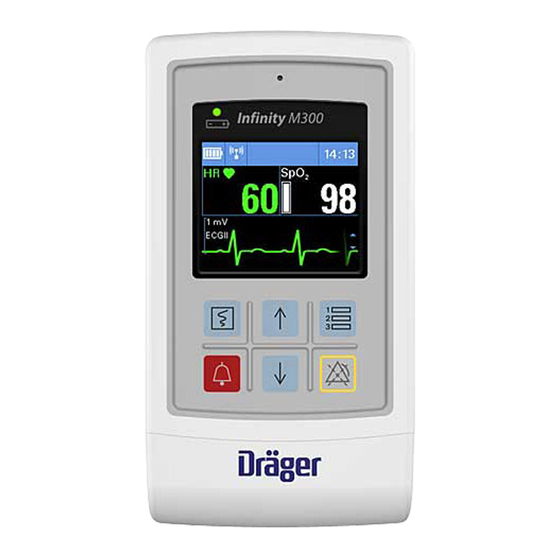
Page 45: Front Panel Of The M300
System overview Front panel of the M300 The following illustration shows the elements of the front panel of the M300: A Speaker for audio alarm signals B Keys C Battery compartment D Battery symbol indicating the remaining charge E Battery status LED Battery status LED of the M300 When the M300 screen is enabled, the battery symbol (D) indicates the available battery power. -
Page 46: Low Battery Alarm
System overview Low battery alarm When the battery power level has reached approximately 30 minutes of remaining charge, a Low battery message is reported visually and acoustically at both the ICS and M300/M300+ to indicate that the battery is low. The M300/M300+ displays the Low battery status once every three minutes, plus or minus five seconds. -
Page 47: Keys Of The M300
System overview Keys of the M300 Function Depending on the enabled setting at the ICS (see page 205), pressing this key does one of the following: – Generates a strip recording and stores an event at the ICS – Cancels a strip recording that was initiated from the M300 If the Staff alert setting is enabled at the ICS (see page 205), pressing this key does the following: –... -
Page 48: Back Panel Of The M300
System overview Back panel of the M300 The following illustration shows the elements of the back panel of the M300: A Cover for SpO2/Aux port B ECG lead connector C Lead wire diagram D Bedside Charger interface NOTE The SpO2 port is also used to run diagnostics. If a service mode message appears, contact your technical personnel. -
Page 49: Overview Of The Bedside Charger
System overview Overview of the Bedside Charger The following illustration shows a Bedside Charger which is used to charge the battery of the M300. For information on how to charge the battery, see “Using the Bedside Charger” on page 95. Avoiding charger and adapter damage To avoid causing damage to the Bedside Charger, the wall adapter should be grasped firmly and pulled straight from the wall when unplugging the charger. -
Page 50: M300 Screen Examples
System overview M300 screen examples Power on/off To turn on and off the Infinity M300/M300+, simultaneously press the Up ( ) arrow and Down ( ) arrow keys located in the middle of the Infinity M300/M300+ panel (shown circled in red in the illustration). NOTE M300/M300+ device settings, including clinical data and current alarm settings, are retained for a maxi- mum of 2 minutes after the device is powered off. -
Page 51: Overview Of The Central Charger
System overview Overview of the Central Charger The M300 Central Charger is a charging station used to store and recharge the batteries of up to ten unused M300s temporarily. The Central Charger is intended to be used outside the patient vicinity. The following illustration shows a Central Charger and some of its identifiable parts. -
Page 52: Infinity M300
System overview Infinity M300+ M300+ front of the device The following figure shows the M300+ front of the device. NOTE Figures of products and screen content in this document may differ from the actual products depending on configuration and design. Speaker for acoustic alarm signal Status LED Battery charge symbol... -
Page 53: M300+ Swappable Battery
System overview M300+ swappable battery The new Infinity M300+ operates with a swappable, externally rechargeable battery with the following specifications: Battery recharging time of approximately 3.5 hours Battery swaps retain clinical data and current alarm settings for approximately two minutes ... -
Page 54: Battery Safety Information
System overview Battery safety information Observe the following warnings and cautions for the swappable battery. WARNING Risk if the swappable battery is not replaced properly. If the swappable battery is not reattached or serviced and replaced properly, short circuits and high temperatures leading to explosion or fire may occur. -
Page 55: Preventive Maintenance
System overview M300+ with swappable battery Typical Battery Run Time Load Conditions 802.11 b/g/n 2.4 GH 18 hours – ECG – Continuous SpO 802.11 a/n 5 GH 18 hours – Display off – Audio off Preventive Maintenance The following table shows the preventive maintenance interval for the M300+ swappable battery: Component Interval Measure... -
Page 56: Charge Status For Swappable Battery Attached To The M300
System overview Charge status for swappable battery attached to the M300+ The M300+ LED indicates battery charge status as follows: Battery charge status Blinks green every 5 seconds Power on Blinks amber every 5 seconds Low battery charge To check the charge status on the swappable battery When you press the TEST button on the M300+ swappable battery, the battery LEDs light to indicate the battery charge status. - Page 57 System overview Charge Indicator Lights Connector Contacts 1 2 3 4 4 LEDs indicates a 90-100% charge TEST button 3 LEDs indicates a 64-89% charge 2 LEDs indicates a 38-63% charge 1 LED indicates a 11-37% charge Note: When the charge is less than 11%, one LED will blink.
-
Page 58: To Insert The Swappable Battery Into The M300
System overview To insert the swappable battery into the M300+ 1 Press the buttons on the swappable battery. 2 Align and insert the battery into place. 3 Slide the battery retainer down over the M300+ into place above the battery. NOTE Make sure the swappable battery correctly aligns with the M300+ before securing into place. -
Page 59: M300+ Battery Charging Station For Swappable Batteries
System overview M300+ battery charging station for swappable batteries The wall-mountable or counter top M300+ battery charging station recharges up to 10 M300+ batteries at a time. Contact your service representative for the wall mounting installation instructions. Approximate charging time is 10 batteries within 4 hours. The charging station provides auto shut off to prevent overcharging, and indicates charging status through illuminated LEDs. -
Page 60: Inserting The Swappable Battery Into The Charger
System overview Inserting the swappable battery into the charger 1 After removing the swappable battery from the M300+, insert it into the charging station. 2 Press the battery into place. Removing the swappable battery from the charger 1 Press the two tabs on each side of the swappable battery. 2 Pull the battery up to remove. -
Page 61: Device Symbols
System overview Device symbols The following table lists the hardware device symbols displayed on various Dräger hardware. Symbol Description Read accompanying IFU for specific safety information. Refer to the instruction manual/booklet. Electrical connectors caution symbol On/off AC power Defibrillator-proof equipment, type CF Non-disposable part IPX1 Protected against dripping water... - Page 62 System overview Symbol Description ESD warning Rx only Caution: Federal law restricts this device to sale by or on the order of a physician European Union Representative Device part number and revision Device serial number Manufacturer Date of manufacture Complies with the European Medical Device Regulation (EU) 2017/745 Complies with applicable EU regulations and directives.
- Page 63 System overview Symbol Description Underwriters Laboratories certification (Canada and US) BSMI certification (Taiwan) China Compulsory Certification ETL listed GOST-R certification Certification that device is tested to comply with 802.11 b/g standards for interop- erability of wireless devices by WI-FI Alliance Certification marking and number for wireless devices with FCC approval FCC ID: Certification that Industry Canada technical specifications were met...
- Page 64 System overview Symbol Description INMETRO certification mark TÜV Rheinland testing approval Chinese Metrological Compliance symbol with approval number Expiration date Quantity China RoHS mark Do not re-use, single patient use Do not re-use Not made with natural rubber latex Instructions for use – Infinity ®...
- Page 65 System overview Symbol Description Not made with natural rubber latex Not made with natural rubber latex Medical Device Caution: Federal law restricts this device to sale by or on the order of a physician. For USA: Rx only Keep this device outside the MRI scanner room Importer Importer Revision index...
-
Page 66: Abbreviations
System overview Abbreviations The following table lists the abbreviations used in these instructions for use and those that are displayed on the ICS and/or M300. For any abbreviations of parameters originating from external devices, refer to the corresponding instructions for use. Abbreviation Description % Paced Percentage of paced beats... - Page 67 System overview Abbreviation Description Advisory (alarm) Life-threatening (alarm) Left ventricular pressure Pulmonary arterial pressure Pulse rate from SpO2 PVC/min Rate of PVC per minute Resistance Right arm (ECG) Right leg (ECG) Ventricular run Serious (alarm) SpO2 Oxygen saturation measured by pulse oximetry ST(x) ST deviation of lead (x) STd(x)
- Page 68 This page has been left blank intentionally. Instructions for use – Infinity ® M300 and M300+ series – VG3.0...
-
Page 69: Operating Concept
Operating concept Operating concept Overview of M300 operating concept ..70 M300....... . . 70 M300 terminology . -
Page 70: Overview Of M300 Operating Concept
Operating concept Overview of M300 operating concept NOTE The ICS is the primary user interface and alarm annunciator for Infinity M300 patient data. M300 The M300 is a patient-worn transceiver used to monitor adult and pediatric patients. It uses the ICS as the primary patient monitoring display and primary alarm source. -
Page 71: Ics Components
Operating concept – Remote Telemetry Viewport a remote viewport represents a patient who is assigned to an ICS Main screen, but is actually ad- mitted to a different ICS. ICS components The following diagram shows one possible configuration with an ICS. A Wireless monitor B M300 C Docked monitor... -
Page 72: Telemetry Monitoring
Operating concept F Infinity network G Primary displays in dual-configuration H Mouse Keyboard J CPU of the ICS K Wireless access points Telemetry monitoring The Infinity M300 monitors ECG and SpO parameters for adult and pediatric patients. M300 patients typically require ambulatory activity as part of their therapeutic regimen. To provide comfort for mobile patients, the M300 should be placed in a disposable pouch (part number MS22905), a reusable shower pouch (part number MS32401), or the patient's hospital gown pocket while the patient is ambulatory. -
Page 73: M300 Power
Operating concept M300 power The Infinity M300 has a rechargeable battery. When the M300 screen is active, a battery symbol ( displays to indicate the remaining battery power. When the M300 is in power-save mode, the LED can be used to identify the status of the battery. Battery life is approximately 12 months. CAUTION Contact your technical personnel when the M300 battery requires replacing. -
Page 74: Minimum Alarm Volume
Operating concept – If the volume control has been enabled in the configuration menu, you can adjust the M300 alarm vol- ume freely in the ICS BedView for the M300, and on the M300 transmitter. – If the volume control is disabled in the configuration menu, you will be able to change the alarm volume in the ICS BedView for the M300, but you will not be allowed to access the alarm volume menu on the M300 transmitter. -
Page 75: Communicating With The Infinity Network
Operating concept Communicating with the Infinity network The Infinity network allows data exchange among Infinity bedside monitors, M300, and the ICS. The Infinity network supports wired and wireless devices. WARNING Loss of communication between the ICS and a monitor is possible. If the ICS loses communication with the Infinity Network, an audio alarm signal sounds at the ICS and displays a message indicating that the bedsides are offline. -
Page 76: Local Ics
Operating concept Local ICS A local ICS is the primary display for all admitted M300s. The ICS also provides the primary alarm signals for any network issues related to recorders. The ICS makes its M300 patients available to the Infinity network for remote viewing by any remote ICS or bedside monitor. -
Page 77: Communication Management
Operating concept Communication management The following table summarizes some of the special circumstances that affect communication between the ICS, the M300, and bedside monitors. What happens if... Behavior the ICS goes offline (for example, due to a – The ICS stops displaying all patient data and disconnected network cable)? sounds a one-shot alarm. -
Page 78: Moving An M300/Patient From One Room (Viewport) To A Different Room (Viewport)
Operating concept Moving an M300/patient from one room (viewport) to a different room (viewport) The following instructions describe how to move a patient from the current viewport (represented by A in the following illustration) to a ’Discharged’ viewport (represented by B). T123_01 T123_08 1 Select the BedView of the new viewport (B) -
Page 79: Supported Symbols
Operating concept A new Question dialog displays when an M300 patient is moved to a new room (viewport). For viewports on the same ICS, the dialog contains the following buttons: – Cancel – Move – moves the M300 patient to the new viewport, and then discharges the patient from the original viewport. - Page 80 Operating concept Symbol Possible Locations Description – In the header bar of the viewport, to the This symbol appears when a monitor is in left of the bed label wireless mode. – In header bar of the BedView, to the left of the bed label –...
-
Page 81: Electronic Patient Data Transfer
Operating concept Electronic patient data transfer An electronic patient data transfer allows you to move patient data across the Infinity network from one device to another using the ICS. A patient data transfer for wired and wireless monitors behaves the same. For example, you can transfer the data of an M300 at the ICS to most bedside monitors on the Infinity network. -
Page 82: Transferring Patient Data
Operating concept Transferring patient data The following diagram shows the Transfer page from which you initiate a data transfer. A Transfer tab B Arrow button for selecting another care unit C Selected care unit label D List of beds in selected care area (must be in Standby to be available for transfer) E Start transfer button Instructions for use –... - Page 83 Operating concept To transfer data from a bedside monitor to an M300 In the following procedure, the letters in parentheses refer to the letters of the Transfer page diagram. 1 Put the source bedside monitor in standby mode. Only patients in standby mode are candidates for transfer.
-
Page 84: Ics And M300 Online Help
Operating concept To transfer data from an M300/M300+ to another M300/M300+ 1 Put the M300/M300+ (containing the data you want to transfer) into standby mode (see "Enabling standby mode" on page 87). Only patients in standby mode are candidates for transfer. 2 Proceed to the parameter box of the M300/M300+ you want to transfer the data to. -
Page 85: Standby Mode
Operating concept Standby mode You can temporarily interrupt patient monitoring by placing the monitor in standby. For an M300, standby mode can only be enabled from the ICS. Standby mode has the following effect: – The Standby banner is displayed in the waveform area of the ICS Main screen, in the BedView of the patient. -
Page 86: Standby/ Discharge Page
Operating concept Standby/ Discharge page The following diagram shows the Standby/ Discharge page for placing an M300 in standby. A Standby/ Discharge tab B Standby On button C Standby Off button D Event duration selection list for standby mode E Admit/Standby button F Apply button G Undo button H Patient Discharge button... -
Page 87: Enabling Standby Mode
Operating concept Enabling standby mode The letters appearing in parentheses (below) refer to the diagram of the Standby/ Discharge page.You can only initiate standby mode for an M300 from the ICS. To enable standby mode 1 Select the parameter box of the M300 patient you want to place into standby mode, or select the pa- tient name or bed label from the Main screen viewport (if using this method, skip the next step). - Page 88 Operating concept To cancel standby mode at the ICS The letters in parentheses refer to the diagram on page 86. Option 1: 1 Select the parameter box of the M300 patient you wish to take out of standby. Once in BedView, the banner displays Standby. Select here to resume monitoring. 2 Select the Admit/Standby button (E) on the BedView menu bar to display the Admit/Standby dialog window.
-
Page 89: M300 User Interface
Operating concept M300 user interface The following sections describe the user interface of the M300. The screen of the M300 is divided into the following main areas. A Arrows on the screen indicate that you can scroll through the waveform using the arrow keys on the M300 (see "M300 keypad"... -
Page 90: M300 Header Bar
Operating concept M300 header bar The header bar appears along the top of the M300. Unless an alarm condition is present, the header bar always appears blue. During an alarm, the message area of the header bar (H) appears in the color of the associated alarm grade. -
Page 91: M300 Keypad
Operating concept M300 keypad The following diagram shows the keypad of the M300 which allows you to execute numerous functions. For a detailed description of these keys, see "Keys of the M300" on page 47. M300 waveforms Waveform colors follow the colors selected at the ICS. For details on the waveform color, refer to the Instructions for use Infinity CentralStation Wide, Software VG4.0 or later. - Page 92 This page has been left blank intentionally. Instructions for use – Infinity ® M300 and M300+ series – VG3.0...
-
Page 93: Charging The M300 Battery
Charging the M300 battery Charging the M300 battery Overview ......94 Battery status LED ..... 94 Using the Bedside Charger . -
Page 94: Overview
Charging the M300 battery Overview This section describes the following basic assembly tasks: – "Battery status LED" on page 94 – "Using the Bedside Charger" on page 95 – "Using the Central Charger" on page 97 Battery status LED The battery LED on the M300 indicates the status of the battery charge. The following table describes the various indications of the battery status LED. -
Page 95: Using The Bedside Charger
Charging the M300 battery Using the Bedside Charger The following illustration shows a Bedside Charger, which is used to charge an individual M300. When the green LED (A) of the Bedside Charger is illuminated, the Bedside Charger is connected to power and is ready to charge an M300. - Page 96 Charging the M300 battery 3 Press the top of the M300 toward the back of the Bedside Charger until it snaps into place. Behavior when the M300 is docked to the Bedside Charger – The wireless communication of the M300 is disabled, causing the wireless icon ( ) to disappear from the M300 display –...
-
Page 97: Using The Central Charger
Charging the M300 battery 1 Grab the M300 on the top and carefully pull it away from the Bedside Charger. 2 Lift the M300 out of the Bedside Charger. When the M300 is removed from the Bedside Charger, the battery status LED indicator flashes once every 5 seconds. - Page 98 Charging the M300 battery To plug in the Central Charger 1 Plug one end of the power cable in the Central Charger connector (E). 2 Plug the other end of the power cable into an appropriate power outlet. The LED (C) lights up green when the Central Charger is plugged in. A M300 devices placed in the Central Charger B Available charging slots on the Central Charger C Power LED...
- Page 99 Charging the M300 battery To place the M300 into the Central Charger Place the bottom of the M300 into one of the empty slots (B) and push it back until it is firmly seated. To remove the M300 from the Central Charger ...
- Page 100 This page has been left blank intentionally. Instructions for use – Infinity ® M300 and M300+ series – VG3.0...
-
Page 101: Getting Started
Getting started Getting started Overview of monitoring a patient ..102 Turning the M300 on/off ....102 Telemetry/Parameters dialog window (BedView in ICS) . -
Page 102: Overview Of Monitoring A Patient
Getting started Overview of monitoring a patient This chapter describes the steps necessary to start monitoring a patient with the M300. Specifically, this chapter describes the following procedures: – Turning the M300 on/off – Admitting/discharging patients Turning the M300 on/off To turn the M300 on ... -
Page 103: Telemetry/Parameters Dialog Window
Getting started To turn the M300 off 1 Simultaneously press and hold both arrow keys (A) and (B) for 3 seconds. 2 Select the up arrow to highlight Yes. 3 Press the button to confirm the shutdown. NOTE M300/M300+ device settings, including clinical data and current alarm settings, are retained for a maxi- mum of 2 minutes after the device is powered off. - Page 104 Getting started For descriptions of the tab contents, refer to the following pages corresponding to each tab: – Layout See "Layout/ Parameters > Layout page" on page 216 – ECG See "Layout/ Parameters > ECG page" on page 221 – SpO2 See "Layout/ Parameters >...
-
Page 105: M300 Demographics Screen
Getting started M300 Demographics screen The Infinity M300 two Demographic screens display patient demographic information. All patient demographic information is received from the ICS. Use the Up/Down arrows to jump from screen to screen. Screen 1 Name Bed label Care unit Patient category Adult / Pediatric Use up and down arrows to go from... -
Page 106: Admitting A Patient
Getting started Admitting a patient You can admit M300 patients at the ICS for central monitoring. However, for M300 patients, the ICS is the primary display. Therefore, you cannot monitor patients with an M300 without also admitting them to the ICS. -
Page 107: Admitting A New M300 Patient
Getting started Admitting a new M300 patient Whenever you turn on an M300 and previous patient data is stored on the M300, the New patient? Yes/No screen appears automatically. This screen allows you to decide whether the currently-stored patient data remains or is deleted to make room for a new patient. -
Page 108: Admitting Under Special Circumstances
Getting started Admitting under special circumstances The following table lists certain conditions that affect a patient admission. Circumstance Effect on admit functions The M300 cannot communicate with the – A medium-priority alarm sounds at the ICS. network. – Patient admission is not possible. Admitting a patient at the ICS You can admit a patient in the following two ways: –... -
Page 109: Populating Patient Data Over The Network
Getting started 8 Enter the patient’s birth date in the Date of birth field (E) – Day, Month, Year. 9 Enter the admit date in the Admit date fields (F) – Day, Month, Year. 10 Enter the weight of the patient in the Weight field (G). For M300 patients, the supported weight range is: 0.1 kg to 350 kg (1 lb to 772 lb). -
Page 110: Discharging A Patient
Getting started 4 Enter the patient ID in the Patient ID field on the Demographics page (B). 5 Select the Get data button (L) in the Demographics page. The Get data button appears grayed out and is not selectable when the HIS is not available. The button is also not selectable when the ICS is disconnected from the network. -
Page 111: Discharging An M300+ Patient
Getting started Discharging an M300+ patient Patient discharge occurs from the ICS as well as from the M300+. To discharge a patient from the M300+ screen, do the following: 1 On the M300+ keypad, press the Staff alert setting key and the Alarm pause setting simultaneously for 3 seconds. -
Page 112: Patient Categories
Getting started Patient categories The patient category setting controls alarm and arrhythmia settings, the QRS sensitivity, and so on. Whenever you admit a new patient at the ICS, the patient category matches the setting of the ICS for the M300. A corresponding symbol (see page 79) appears in the viewport header bar in ICS and in the header bar of the BedView in ICS. - Page 113 Getting started NOTE Changing the patient category of an M300 causes the ICS database (Full disclosure, Events, and trends) to behave as if a new patient has been admitted, which creates a brand new patient record. Although the original patient record (Full disclosure, Events, and trends) is not erased, it is changed to an archived state.
- Page 114 This page has been left blank intentionally. Instructions for use – Infinity ® M300 and M300+ series – VG3.0...
-
Page 115: Alarms
Alarms Alarms Overview of alarms..... 116 Alarm groups ......133 Alarm priorities . -
Page 116: Overview Of Alarms
Alarms Overview of alarms The ICS is the primary alarm annunciator for the M300. The ICS displays visual and audio alarms based on information received from the source device. Although audio tone characteristics cannot be changed by the user, three distinctive alarm patterns (IEC fast, IEC slow, and Infinity) are provided from which you can select to best fit your environment. -
Page 117: Alarm Priorities
Alarms Alarm priorities Every alarm condition is assigned to one of three priorities: high, medium, or low. Visual and audio alarm signals indicate the level of the alarm priority. For more information on how alarm priorities affect alarm reporting, see "Alarm signals" on page 122. High-priority alarm conditions All high-priority alarms are physiological alarm conditions that can be life-threatening and require immediate intervention. -
Page 118: M300 Alarm Processing
Alarms When a parameter is alarming, the parameter box of the BedView page and the entire parameter area of the viewport of the alarming bedside monitor flashes in the color representing the alarm priority (red for high, yellow for medium, or cyan for low). When multiple alarm conditions occur simultaneously, the parameter boxes flash for all alarming parameters. -
Page 119: Parameter Box Flashing Rate
Alarms Parameter box flashing rate The parameter box will flash at a 50% duty cycle for high- and medium-grade priority alarms, as follows: High-priority alarm = 1.4 to 2.8 Hz Medium-priority alarm = 0.4 to 0.8 Hz The parameter box for Low-priority alarms will remain solid (no flashing). The M300 transceiver sends audio pause information to the network so the ICS can display the "Audio paused"... -
Page 120: Latching And Non-Latching Alarm
Alarms Latching and non-latching alarm When an alarm condition no longer exists, the associated audible and visual alarms behave in the following manner: – For high-priority alarms Both audible and visual alarm signals normally continue until you acknowledge the alarm, even though the alarm condition has ceased to exist. -
Page 121: Activating Or Deactivating Alarm Validation
Alarms Activating or deactivating alarm validation When alarm validation is enabled (see "Telemetry defaults > Alarms > Device settings tab" on page 214), an alarm condition must exist for a certain period of time before audible and visual alarm signals are triggered. -
Page 122: Alarm Signals
Alarms Alarm signals Visual alarm indicators on the M300 The M300 screen displays visual alarm in the message field and the parameter boxes. For information about alarm signal colors for a bedside monitor, refer to the instructions for use of the specific monitor. A Alarm message field –... -
Page 123: M300 Speaker Alarm Tones
Alarms Alarm volume range Alarm priority level Minimum alarm volume Maximum alarm volume High 39 – 55 dB 64 – 81 dB Medium 42 – 52 dB 67 – 79 dB 41 – 54 dB 65 – 79 dB CAUTION Setting the auditory alarm signal sound pressure levels lower than the ambient levels can impede oper- ator recognition of alarm conditions. -
Page 124: Adjusting The M300 Alarm Volume
Alarms Adjusting the M300 alarm volume The volume of the M300 built-in speaker is adjustable. For more information on configuring the Volume Control of the M300, see page 205. NOTE The M300 alarm volume can be set to Off only while it is displayed at the ICS. If communication is inter- rupted between the network and the M300, the M300 continues monitoring and automatically sets its alarm volume to 100 %. -
Page 125: Pausing Audio Alarms For The M300
Alarms Pausing audio alarms for the M300 You can pause (silence) all active audio alarm signals for an individual patient at their bedside monitor and at the ICS using the Bed audio pause button. The Bed audio pause button appears in the parameter box area of the viewport or in the menu bar of the BedView page. -
Page 126: Pausing Audio Alarms For The M300 From A Remote Network Device
Alarms Pausing audio alarms for the M300 from a remote network device If the Audio pause from remote ICS setting is enabled at the local ICS (see page 214), you can pause (silence) active audio alarm signals from the following devices: –... -
Page 127: Pausing Alarms For The M300 From A Remote Network Device
Alarms Pausing alarms for the M300 from a remote network device You can pause all alarm functions for the M300 from other ICS in the local monitoring units if the Control from remote ICS setting is enabled at the local ICS. Note that, in all cases with the M300, a change in any system setup or telemetry setup from the Main screen menu bar pages will take effect only after the device is re-admitted. -
Page 128: Configuring Alarm Settings For Multiple
Alarms A Parameter labels column B Alarm (on/off) column C Lower limits column D Actual (current) parameter values column E Upper limits column F Archive column G Restore button in the Limits defaults field– restores system default settings; only available for the M300 H Apply button Undo button... - Page 129 Alarms – Record – generates a strip recording. – Store/Rec. – generates a strip recording and stores the event in the disclosure database. 7 Repeat steps 3 through 6 for each parameter you want to configure. Or, select the Auto set button in the Limits field (J), to reset the alarm limits of all the available pa- rameters to automatically calculated values.
-
Page 130: Alarm Setup For Arrhythmia Parameters
Alarms Alarm setup for arrhythmia parameters The following diagram shows the Alarms > Arrhythmia page where you configure alarm settings for arrhythmia parameters. This page consists of a table with setup rows for each arrhythmia parameter. Each setup row consists of several fields for configuring the individual arrhythmia alarm settings. A ARR mode buttons: Off, Basic, Advanced –... -
Page 131: Configuring Arrhythmia Alarm Settings
Alarms Configuring arrhythmia alarm settings In the following steps, the letters in parentheses refer to the diagram of the Alarms > Arrhythmia page (see "Alarm setup for arrhythmia parameters" on page 130). For alarm ranges and defaults for the M300, see "M300 alarm ranges and defaults" on page 134. To configure the arrhythmia alarm settings of a bedside monitor or M300 1 Select the Alarms button in the menu bar of the BedView page. -
Page 132: Auto Setting All Alarm Limits
Alarms Auto setting all alarm limits The auto set function allows you to quickly adjust alarm limits based on preset percentages. The following table lists the percentages for the M300. For other monitors, consult the instructions for use for the specific model. -
Page 133: Storage
Alarms Special conditions for alarm event storage When an alarm is re-enabled (for example, when an alarm condition is valid beyond an audio pause), a new event is not stored. Alarm groups The alarm group feature enables you to configure several bedside monitors as members of a group. This enables the bedside monitors to display the group’s highest priority active alarm at each bedside monitor within that alarm group. -
Page 134: M300 Alarm Ranges And Defaults
Alarms M300 alarm ranges and defaults Parameter ranges and defaults Parameter Alarm limit range Upper limit Lower limit Alarm Alarm defaults defaults default archive default Upper: 25 to 300 bpm 120 bpm 45 bpm Store/Rec. (adult) (adult) Increment: 5 bpm Lower: 20 to 295 bpm 150 bpm 50 bpm... -
Page 135: Arrhythmia Parameter Ranges And Defaults
Alarms Arrhythmia parameter ranges and defaults NOTE Items in parentheses are default values. Parameter Alarm grade Rate (default) Count (default) Alarm archive default factory default AIVR Adult: Not adjustable, Adult: Not adjustable VTach rate –1 (119) Pediatric: Not adjustable, Pediatric: Not adjustable VTach rate –1 (159) ARTF... - Page 136 Alarms Parameter Alarm grade Rate (default) Count (default) Alarm archive default factory default Medium Not adjustable Not adjustable (Rate = VTach) 3 to VTach count –1 (3 to 9) Medium 120 to 200 3 to 10 (3) (150) Increments of 10 Increments of 1 TACH Adult: 100 to 200...
-
Page 137: Monitoring With M300
ECG, arrhythmia, and ST segment monitoring with M300 ECG, arrhythmia, and ST segment monitoring with M300 Overview of telemetry defaults ... 138 Overview of arrhythmia monitoring..152 ECG signal processing and display . -
Page 138: Overview Of Telemetry Defaults
ECG, arrhythmia, and ST segment monitoring with M300 Overview of telemetry defaults This chapter describes heart rate (HR), arrhythmia (ARR), and ST monitoring for the M300. For all other bedside monitors, refer to their respective instructions for use. The M300 calculates and displays heart rate values, identifies paced beats, reports arrhythmia conditions, and measures ST deviations. -
Page 139: Supported Parameters
ECG, arrhythmia, and ST segment monitoring with M300 Supported parameters – ECG: HR (heart rate) – Arrhythmia: ARR (ASY, VF, ARTF, VTach, RUN, AIVR, SVT, CPT, BGM, TACH, BRADY, PAUSE; see page 157 for a description of these arrhythmia modes) and PVC/min –... -
Page 140: Ecg Precautions
ECG, arrhythmia, and ST segment monitoring with M300 ECG precautions WARNING Do not rely solely on the ECG when monitoring seizure-prone patients. Electrical artifacts of non- cardiac origin, such as seizure, may prevent detection of certain arrhythmias. ECG display On the ICS and M300, the ECG display consists of: –... -
Page 141: Ecg Parameter Box In The Ics Bedview
ECG, arrhythmia, and ST segment monitoring with M300 ECG parameter box in the ICS BedView ECG parameter box on the M300 A Parameter label B Heart blip that flashes with each detected pulse (if pacer detection is enabled, the symbol appears as when a paced beat is detected) C Heart rate value –... -
Page 142: Ecg Waveform On A Bedview Page Of The Ics
ECG, arrhythmia, and ST segment monitoring with M300 ECG waveform on a BedView page of the ICS For information on the ECG waveform on a BedView page in the ICS, refer to the Instructions for use Infinity CentralStation Wide, Software VG4.0 or later. ECG waveform on the M300 A Selected waveform scale B Lead label... -
Page 143: Ecg Electrode Colors
ECG, arrhythmia, and ST segment monitoring with M300 ECG electrode colors Electrodes are labeled and color-coded according to IEC (IEC1) and AHA (IEC2). AHA/US Electrode location Yellow Black Left arm Green Left leg White Right arm Black Green Right leg (neutral) White Brown Moveable chest... -
Page 144: Electrode Placement
ECG, arrhythmia, and ST segment monitoring with M300 Electrode placement Standard configuration, three electrodes (IEC/AHA) Instructions for use – Infinity ® M300 and M300+ series – VG3.0... -
Page 145: Standard Configuration, Five Electrodes
ECG, arrhythmia, and ST segment monitoring with M300 Standard configuration, five electrodes (IEC/AHA) Instructions for use – Infinity ® M300 and M300+ series – VG3.0... -
Page 146: Pacer Configuration, Five Electrodes
ECG, arrhythmia, and ST segment monitoring with M300 Pacer configuration, five electrodes (IEC/AHA) Instructions for use – Infinity ® M300 and M300+ series – VG3.0... -
Page 147: Accessing The Ecg Setup Page
ECG, arrhythmia, and ST segment monitoring with M300 Standard configuration, six electrodes (IEC/AHA) Accessing the ECG setup page The ECG setup page for a telemetry patient can only be accessed through the BedView page of the ICS. 1 Open the BedView page by selecting the viewport of the telemetry patient in the ICS Main screen. 2 Select the Telemetry/ Parameters button. -
Page 148: Ecg Parameter Setup Functions
ECG, arrhythmia, and ST segment monitoring with M300 ECG parameter setup functions All ECG parameter setup functions take place in the ECG setup page (see page 147). To configure the alarm functions, refer to the Instructions for use Infinity CentralStation Wide, Software VG4.0 or later. -
Page 149: Monitoring Paced Patients
ECG, arrhythmia, and ST segment monitoring with M300 Monitoring paced patients When pacer detection is enabled, the M300/M300+ uses the following specifications to identify a pulse as a pacer pulse: Amplitude: ±2 to ±700 mV Width: 0.2 to 2.0 ms , ≤100 μs Rise/Fall times (min.): 0.1 d Overshoot (min.): 0.025, ≤2 mV... - Page 150 ECG, arrhythmia, and ST segment monitoring with M300 – Paced pulses of 0.2 – 0.5ms and amplitude voltage from -2.0 – 700 mV with overshoot greater than 0.3% may result in missed valid heart beats, contributing to a lower than actual heart rate. Dräger recommends closely monitoring paced patients.
-
Page 151: Pacer Fusion Mode
ECG, arrhythmia, and ST segment monitoring with M300 Pacer Fusion mode Pacer Fusion mode offers increased detection sensitivity to fused paced beats, which reduces false asystole and low heart rate alarms. WARNING Pay close attention to pacemaker patients being monitored in fusion mode because this mode may increase the risk of falsely counting pacemaker spikes as QRS complexes, thus failing to detect cardiac arrest. -
Page 152: Overview Of Arrhythmia Monitoring
ECG, arrhythmia, and ST segment monitoring with M300 – Transcutaneous electrical nerve stimulators Signals from transcutaneous electrical nerve stimulators (TENS) often resemble pacemaker signals and can be labeled as such. The M300 can reject valid QRS complexes, which follow misinterpreted TENS signals. -
Page 153: M300/M300+ Arrhythmia Processing
ECG, arrhythmia, and ST segment monitoring with M300 M300/M300+ Arrhythmia processing Arrhythmias are identified using an internal detection process. This process does the following: – Filters out ECG signal artifacts – Detects the beat pattern – Classifies the beat pattern –... -
Page 154: Selecting Arrhythmia Leads
ECG, arrhythmia, and ST segment monitoring with M300 Selecting arrhythmia leads Appropriate lead selection is essential for accurate arrhythmia monitoring. It is ideal to assign the two best ECG leads as the arrhythmia monitoring leads. The following two options are available: –... - Page 155 ECG, arrhythmia, and ST segment monitoring with M300 The following table describes the ECG lead status and notifications. Lead status Notification One lead is not detected, but is not required to <xx> Lead off message will be displayed on the process the heart rate or arrhythmia.
- Page 156 ECG, arrhythmia, and ST segment monitoring with M300 The following table lists the ECG lead functionality for 3-, 5-, or 6-lead ECG cable set. ECG cable Disconnected Selected Neutral Valid leads available for ECG electrode(s) processing lead electrode processing None (RA, LA, and LL are valid) Any one or more None...
-
Page 157: Recommended Remedies For Lead-Off
ECG, arrhythmia, and ST segment monitoring with M300 Recommended remedies for lead-off notifications Inspect and periodically replace electrodes according to the electrode manufacturer’s recommendation. Inspect ECG wire connections from M300/M300+ to patient electrodes. Inspect and replace faulty lead sets. ... -
Page 158: Arrhythmia Display
ECG, arrhythmia, and ST segment monitoring with M300 Eight or more consecutive normal beats, with an average rate ≤ BRADY Bradycardia bradycardia rate. PAUSE Pause A sequence of two normal beats occur with an Normal-Normal in- terval greater than the PAUSE rate times the average N-N interval (±100 ms). -
Page 159: Accessing The Arrhythmia Setup Page
ECG, arrhythmia, and ST segment monitoring with M300 Accessing the Arrhythmia setup page The Arrhythmia setup page for a telemetry patient can only be accessed through the BedView page of the ICS. 1 Open the BedView page by selecting the parameter box of the telemetry patient in the ICS Main screen. - Page 160 ECG, arrhythmia, and ST segment monitoring with M300 A Fiducial point B ST measurement point C ST level D QRS offset E QRS onset F ISO point The ST algorithm has been tested for accuracy of the ST segment data. The significance of the ST segment changes need to be determined by a clinician.
-
Page 161: Connecting Lead Wire Sets For St Monitoring
ECG, arrhythmia, and ST segment monitoring with M300 Connecting lead wire sets for ST monitoring ST monitoring uses the following lead configurations for each available ST monitoring mode: – Standard ST monitoring – uses the standard 3- 5-, and 6-lead wire sets. For more information connect- ing lead wire sets, see page 144. -
Page 162: 12-Lead Trust Monitoring
ECG, arrhythmia, and ST segment monitoring with M300 12-lead TruST monitoring This feature offers real-time assessment of 12-lead ST deviations, with only six electrodes, which provide eight measured ECG leads and four derived chest leads. The derived leads are identified by adding the letter ‘d’... -
Page 163: St Display
ECG, arrhythmia, and ST segment monitoring with M300 ST display The ST parameter box displays in the following locations: – The viewports in the ICS Main screen – The BedView page of the patient NOTE The M300 does not display the ST values but does show ST alarm messages. The ST parameter box and alarm messages appear in the viewport and the BedView page of the ICS. -
Page 164: Viewing All St Complexes
ECG, arrhythmia, and ST segment monitoring with M300 In the ST complex tab, a solid yellow vertical line marks changes in ST points (ISO or measurement). Viewing all ST complexes The number of displayed ST complexes depends on the connected lead wire set. To access the multiple ST complexes page 1 Open the BedView page by selecting the parameter box of the telemetry patient in the ICS Main screen. - Page 165 ECG, arrhythmia, and ST segment monitoring with M300 A ST complexes tab B Waveform label (for each waveform) C ST panels for each monitored ST lead (including scale, ST measurement point, ISO point, and refer- ence point) D Save reference button E Save reference button (on, off) F Undo button G Size [mV] selection control...
-
Page 166: Zooming In On An St Complex
ECG, arrhythmia, and ST segment monitoring with M300 Zooming in on an ST complex You can zoom in on a single ST complex to view it in greater detail. To access a single ST complex 1 Open the BedView page by selecting the parameter box of the telemetry patient in the ICS Main screen. -
Page 167: St Measuring And Iso Points
ECG, arrhythmia, and ST segment monitoring with M300 A ST complexes tab B ST label (unique for each ST lead) C Scale D Waveform area E Save reference button F Reference button (on, off) G Undo button H Size [mV] selection control Set points button J ST measuring point selection controls K ISO point adjustment controls... -
Page 168: St Reference
ECG, arrhythmia, and ST segment monitoring with M300 ST reference You can save ST reference complexes as a reference point for future ST deviation measurement comparisons. The first time you relearn ECG complexes, the current ST data are saved as a reference data. -
Page 169: St Parameter Setup Functions
ECG, arrhythmia, and ST segment monitoring with M300 ST parameter setup functions All ST parameter setup functions take place in the ST setup page (see page 168). To configure the alarm functions, refer to the Instructions for use Infinity CentralStation Wide, Software VG4.0 or later. - Page 170 ECG, arrhythmia, and ST segment monitoring with M300 – The patient category changes at the M300 During the learning phase, which lasts approximately 30 to 40 seconds, the message ECG relearn appears in the viewport header bar message area. In addition, the message LRN appears in the ECG parameter box.
-
Page 171: Masimo And M300
and pulse rate monitoring with Masimo and M300 and pulse rate monitoring with Masimo and M300 Overview of SpO monitoring with Masimo ......172 Supported parameters . -
Page 172: Supported Parameters
and pulse rate monitoring with Masimo and M300 Overview of SpO monitoring with Masimo This chapter describes SpO2 monitoring for the ICS with M300 devices configured for use with Masimo sensors. For all other bedside monitors, refer to their respective instructions for use. SpO2 monitoring is only possible when the SpO2 license option is enabled at the ICS, an SpO2 license is available, and SpO2 monitoring is set to On. -
Page 173: Spo 2 Precautions
and pulse rate monitoring with Masimo and M300 precautions Interfering Substances: Carboxyhemoglobin may erroneously increase measurement values. The level of increase is approximately equal to the amount of carboxyhemoglobin present. Dyes, or any substance containing dyes that change arterial pigmentation, may cause erroneous measurement values. NOTE You can configure the alarm priority for the SpO2 sensor off alarm condition. -
Page 174: Starting Spo 2 Monitoring On A Patient
and pulse rate monitoring with Masimo and M300 NOTE A functional tester can be used to measure the total error of a pulse oximeter monitor-probe system if a particular calibration curve has been independently demonstrated to be accurate for that system. The functional tester can then measure how accurately a particular pulse oximeter is in reproducing the cali- bration curve. -
Page 175: Connecting The Spo
and pulse rate monitoring with Masimo and M300 Connecting the SpO cable to the M300 The SpO2 cable connects directly to the M300. To connect the SpO cable to the M300 1 Attach the blue connector of the intermediate cable (B) to the blue SpO2 connector (A) of the M300. 2 Attach the appropriate sensor to the end of the intermediate cable (C). -
Page 176: Applying The Sensor
and pulse rate monitoring with Masimo and M300 – Arterial occlusion proximal to the sensor – Patient is in cardiac arrest or is in shock – Bright light causing erratic measurement or missing values. Cover the sensor with opaque material if it is likely to be exposed to direct bright light. -
Page 177: Turning Spo 2 Monitoring On/Off
and pulse rate monitoring with Masimo and M300 Turning SpO monitoring on/off 1 Access the SpO2 setup page at the ICS, (see "Accessing the SpO2 page" on page 179). 2 Select On for SpO2 monitoring. 3 Optional: Select On for Bar graph to display a pulse bar in the SpO2 parameter box on the M300 (the pulse bar does not display on the ICS). -
Page 178: Spo 2 Parameter Box In The Ics Bedview
and pulse rate monitoring with Masimo and M300 parameter box in the ICS BedView parameter box on an M300 A SpO2 label B SpO2 saturation value C Crossed triangle symbol when the SpO2 alarm is turned off. D PLS label E Crossed triangle symbol when the pulse alarm is turned off. -
Page 179: Accessing The Spo2 Page
and pulse rate monitoring with Masimo and M300 Accessing the SpO page 1 Open the BedView screen by selecting the viewport of the telemetry patient on the ICS main screen. 2 Select the Telemetry/ Parameters button. 3 Select the Layout/ Parameters tab (if not already selected). 4 Select the SpO2 tab. - Page 180 This page has been left blank intentionally. Instructions for use – Infinity ® M300 and M300+ series – VG3.0...
-
Page 181: Nellcor And M300
and pulse rate monitoring with Nellcor and M300 and pulse rate monitoring with Nellcor and M300 Overview of SpO monitoring with Nellcor . 182 Supported parameters ....182 precautions . -
Page 182: Supported Parameters
and pulse rate monitoring with Nellcor and M300 Overview of SpO monitoring with Nellcor This chapter describes SpO2 monitoring for the ICS with M300 devices configured for use with Nellcor sensors. For all other bedside monitors, refer to their respective instructions for use. SpO2 monitoring is only possible when the SpO2 license option is enabled at the ICS, an SpO2 license is available, and SpO2 monitoring is set to On. -
Page 183: Spo 2 Precautions
and pulse rate monitoring with Nellcor and M300 precautions Interfering Substances: Carboxyhemoglobin may erroneously increase measurement values. The level of increase is approximately equal to the amount of carboxyhemoglobin present. Dyes, or any substance containing dyes that change arterial pigmentation, may cause erroneous measurement values. NOTE You can configure the alarm priority for the SpO2 sensor off alarm condition. -
Page 184: Starting Spo 2 Monitoring On A Patient
and pulse rate monitoring with Nellcor and M300 NOTE A functional tester can be used to measure the total error of a pulse oximeter monitor-probe system if a particular calibration curve has been independently demonstrated to be accurate for that system. The functional tester can then measure how accurately a particular pulse oximeter is in reproducing the cali- bration curve. -
Page 185: Connecting The Spo
and pulse rate monitoring with Nellcor and M300 Connecting the SpO cable to the M300 The SpO2 cable connects directly to the M300. To connect the SpO cable to the M300 1 Attach the blue connector of the intermediate cable (B) to the blue SpO2 connector (A) of the M300. 2 Attach the appropriate sensor to the end of the intermediate cable (C). -
Page 186: Patient Preparation For Spo Monitoring
and pulse rate monitoring with Nellcor and M300 Patient preparation for SpO monitoring The following tips provide optimal SpO2 monitoring results but should never replace hospital-approved practices or sensor manufacturer’s recommendations. The accuracy of SpO2 monitoring depends largely on the strength and quality of the SpO2 signal. If a finger is used as a monitoring site, remove any nail polish. -
Page 187: Turning Spo 2 Monitoring On/Off
and pulse rate monitoring with Nellcor and M300 To apply the sensor 1 Select the size and type of sensor that is best suited for your patient. Follow the recommendations of the manufacturer. 2 Position the sensor correctly and attach it to your patient. 3 Connect the sensor to the SpO2 cable (see page 185). -
Page 188: Spo 2 Display
and pulse rate monitoring with Nellcor and M300 display On the ICS and M300, the SpO2 display consists of: – SpO2 parameter box – SpO2 pulse plethysmogram waveform NOTE The pulse plethysmogram waveform is directly proportional to the pulse amplitude strength. The SpO2 parameter box displays in the following locations: –... -
Page 189: Spo 2 Parameter Box On An M300
and pulse rate monitoring with Nellcor and M300 parameter box on an M300 A SpO2 label B SpO2 saturation value C Crossed triangle symbol when the SpO2 alarm is turned off. D PLS label E Crossed triangle symbol when the pulse alarm is turned off. F PLS value G Pulse bar graph –... -
Page 190: Accessing The Spo 2 Setup Page
and pulse rate monitoring with Nellcor and M300 Accessing the SpO setup page 1 Open the BedView screen by selecting the viewport of the telemetry patient on the ICS Main screen. 2 Select the Telemetry/ Parameters button. 3 Select the Layout/ Parameters tab (if not already selected). 4 Select the SpO2 tab. -
Page 191: Recordings/Reports
Recordings/reports Recordings/reports Overview ......192 R50N recorder......193 Recorder setup . -
Page 192: Overview
Recordings/reports Overview The ICS offers a real-time record of its monitoring results on R50N recorders. You can also request various reports and screens to be printed on a configured laser printer. The content of the reports and recordings depend on the configured settings, which can be customized within the Recorders/ Reports setup pages. -
Page 193: R50N Recorder
Recordings/reports R50N recorder Manual and alarm recordings are printed on R50N recorders via the network. Recorder setup A Stop button B mm/s button The R50N recorders have two buttons: – The Stop button stops a recording in progress. – The mm/s button on the recorder’s front panel (Alternate Speed on older recorders) enables you to change the recording speed while a recording is in progress. -
Page 194: Initiating Manual Recordings
Recordings/reports Initiating manual recordings Recordings Required steps Manual recording For an individual patient: (from the Main screen) – Select the Main screen viewport to display a button which, when se- lected, will print the recording. If the patient is discharged or in Standby mode, you cannot request a manual recording. -
Page 195: Manual (Timed) Recordings
Recordings/reports Manual (timed) recordings Manual recordings are strip recordings of a specified duration. These recordings contain delay data originating before the recording is initiated and real-time data acquired after the recording started. NOTE If the patient was monitored for less time than the specified delay, the amount of delay data is adjusted accordingly. - Page 196 Recordings/reports Header information The header of a manual recording contains the following information: – Parameter values at the time the recording starts printing – Patient name and ID number – Date and time The following diagram shows a representation of a typical manual recording: Manual (timed) recording with header A Patient name B Patient ID...
- Page 197 Recordings/reports Diagnostic code Digit Description Possible Definition values Lead processed for VF and None pacer pulse detection ECG filter Monitor Pacer detection On - Artifact Rejection <Medium> Off - Artifact Rejection <Medium> Fusion - Artifact Rejection <Medium> QRS/arrhythmia processing ECG1 & ECG2 ECG1 Instructions for use –...
- Page 198 Recordings/reports Digit Description Possible Definition values Patient category/ <Space> Adult, neither lead completed learning QRS classification Adult, ECG1 lead completed learning Adult, ECG2 lead completed learning Adult, ECG1&2 lead completed learning Neonate No valid lead to process Leads available for processing ECG1 is valid to process ECG2 is valid to process ECG1 &...
-
Page 199: Canceling A Recording
Recordings/reports Digit Description Possible Definition values RESP size Value = (RESP size)/5 (where A-K corresponds to 10-20) <Space> 18, 19 Minutes since breath 00-99 Number of minutes that have elapsed since detector initialization the breath detector was initialized (where 99 corresponds to ≥... -
Page 200: Actions That Affect Recordings
Recordings/reports Actions that affect recordings Action Effect on pending recordings Effect on recordings in progress Patient Discharge Pending recordings are discarded Recording is canceled Edit patient’s demographic No effect No effect data Patient monitoring put in No effect Recording is canceled Standby mode Configuration change of Patient’s pending recordings are... -
Page 201: System Configuration
System configuration System configuration Overview ......202 The Biomed page ..... . 202 Biomed >... -
Page 202: Overview
System configuration Overview This chapter describes the System setup screens, which consist of several setup pages for configuring the ICS and the M300 telemetry functions. Some of these setup pages are password protected and are only accessible to authorized personnel. For more information about configuring the ICS, refer to the Instructions for use Infinity CentralStation Wide, Software VG4.0 or later. - Page 203 System configuration CAUTION The ECG notch filter [Hz] setting can affect ECG waveform artifacts. If there are monitoring performance concerns, contact the hospital’s biomedical department, DrägerService, or specialized service personnel. Biomed > Configure telemetry > General settings tab Selection Settings Description 50, 60 (default) Assigns the M300 ECG notch filter setting.
- Page 204 System configuration Biomed > Configure telemetry > Telemetry devices tab Selection Settings Description User input Enables the installation personnel to add a Add device new M300 device by selecting this button and entering the appropriate information. The Telemetry devices table can accept a maximum of 255 rows.
- Page 205 System configuration Biomed > Configure telemetry > Telemetry settings tab Selection Settings Description Enabled (default), Disabled, Enables installation personnel to activate or Alarm pause deactivate the Alarm pause key for all M300 Per patient devices admitted to the ICS permanently. The Per patient option allows you to activate or de- activate this key for each individual patient af- ter the patient is admitted.
-
Page 206: Telemetry Default Setup (System Setup)
System configuration Telemetry setup defaults The Telemetry defaults window consists of several setup pages for configuring the M300 telemetry system defaults. Some of these setup pages can be password protected and are only accessible to authorized personnel. Telemetry setup is available only when the Telemetry Locked option is enabled. Most setup pages consist of selections for configuring individual features. -
Page 207: The General Settings Page
System configuration The General settings page The Telemetry defaults > General settings page is used to configure general M300-related system default settings. To access the Telemetry > General settings page 1 Select the Telemetry defaults button from the Main menu bar. 2 Select the General settings tab (if not already selected). - Page 208 System configuration Selection Settings Description Enabled (default), Disabled Allows you to activate or deactivate functions Control from re- from other remote ICS devices within the same mote ICS monitoring unit. When set to Enabled, all M300 telemetry devices can be controlled by remote network devices.
-
Page 209: The Alarms Page (Telemetry)
System configuration The Alarms page (telemetry) The Telemetry defaults > Alarms page enables you to configure system default settings relating to alarm annunciation, and change the alarm limits and arrhythmia settings for all M300 devices admitted to that ICS. To access the alarm setup for telemetry 1 Select the Telemetry defaults button on the Main menu bar. - Page 210 System configuration A Alarms tab B Limits tab C Patient category buttons (Pediatric, Adult) D Parameter labels column E Alarm on/off column F Lower limits column G Actual parameter values H Upper limits column Archive column J Apply button K Undo button Instructions for use –...
-
Page 211: Changing Alarm Limits Settings
System configuration Changing alarm limits settings In the following steps, the letters in parentheses refer to the preceding diagram of the Limits page. For related information, refer to page 134. WARNING Setting alarm limits to extreme values may prevent certain alarm conditions from being detected and from being annunciated with audible and visual alarm signals. -
Page 212: Alarms > Arrhythmia Page
System configuration Alarms > Arrhythmia page The following diagram shows an example of the Arrhythmia tab contents from the Alarms page, where you configure default alarm settings for available arrhythmia parameters. As with the previous Limits page, this setup page consists of a table with setup rows for each arrhythmia parameter. - Page 213 System configuration A Alarms tab B Arrhythmia tab C Patient category buttons (Pediatric, Adult) D ARR mode buttons (Off, Basic, Advanced) E Arrhythmia column for identifying the arrhythmia label F Alarm column for selecting an alarm priority G Rate column for setting the rate H Count column for setting the count Archive column J Apply button...
-
Page 214: Telemetry Defaults > Alarms > Device Settings Tab
System configuration 8 Use one of the following settings in the Archive column (I) to determine what happens in response to an alarm: – Off – no event is stored and no recording is generated. – Record – generates a manual recording. –... -
Page 215: Patient
System configuration Selection Settings Description Determines the alarm priority for this alarm ECG leads off Low (default), Medium, High condition. alarm Determines the alarm priority for this alarm Critical battery Medium (default), High condition. alarm Restores alarm limits and arrhythmia settings Restore alarm fac- Restore to factory defaults for all patient categories. -
Page 216: Layout/ Parameters > Layout Page
System configuration – Layout (see page 216) – ECG (see page 221) – SpO2 (see page 222) – ST (see page 222) Layout/ Parameters > Layout page The Layout page enables you to configure the default parameters, scales, and waveforms for each channel that will display in BedView for telemetry patients. - Page 217 System configuration Selection Settings Description Waveform col- – 3-wires - I, II, III Enables you to click in the channel’s Waveform – 5-wires - I, II, III, aVR, aVL, column to make a selection. aVF, V PLS is available as a waveform setting only when –...
- Page 218 System configuration ICS Telemetry defaults screen To set the Adult QRS threshold or Pediatric QRS threshold, navigate to the Telemetry defaults screen and select the Layout/ Parameters tab, then the Layout tab. Reduced Main screen showing vital signs in real time Main menu bar Telemetry Layout Tab page QRS/ARR processing...
- Page 219 System configuration QRS Threshold Depending on the software versions running on the ICS and the M300/M300+ devices, the procedure you follow to set the QRS threshold on the M300/M300+ will differ: If ICS is VG2.1.1 or later, and the M300/M300+ is VG2.4 or later, you set the QRS threshold by a menu selection, either Normal or Low ...
- Page 220 System configuration ANSI/AAMI/ IEC 60601- 2-27:2011 QRS detection amplitude QRS detection amplitude: 0.5 to 5.0 mVp-v RTI QRS threshold detection duration: Adult: 70 to 120 ms Pediatric: 40 to 120 ms Configuring the QRS threshold to Low may extend the QRS detection amplitude to as low as 0.17 mVp- v RTI.
-
Page 221: Layout/ Parameters > Ecg Page
System configuration Layout/ Parameters > ECG page The ECG page enables you to define the system-wide default ECG patient monitoring settings shown in the following table. Selection Settings Description On, Off (default) Enable/disable TruST monitoring of the M300 TruST 12-lead (see "12-lead TruST monitoring"... -
Page 222: Layout/ Parameters > Spo2 Page
System configuration Layout/ Parameters > SpO2 page The SpO2 page enables you to define default system-wide SpO2 monitoring settings, and to adjust the settings displayed in the following table. Selection Settings Description On, Off (default) Enable or disable SpO2 monitoring. SpO2 monitoring SpO2 Monitoring can be enabled for local te- lemetry patients only. - Page 223 System configuration ST setup screen selections: 3-Wire Selection Settings Description I (default), II, III, None Sets ECG lead vector for ST lead 1 param- ST lead %1 eter box Note: %1 is a place- holder for available ST lead 1. mm (default), mV Sets units for ST measurements ST units...
- Page 224 System configuration ST setup screen selections: 6-Wire, TruST OFF Selection Settings Description Sets ECG lead vector for ST lead 1 - 8 pa- ST lead %1 Available selections: rameter box Note: %1 is a place- I , II, III, aVR, aVL, aVF, V, V+, None holder for available ST lead defaults: ST leads 1 - 8.
- Page 225 System configuration ST setup screen selections: 6-Wire, TruST ON Selection Settings Description Sets ECG lead vector for ST lead 1 - 14 pa- ST lead %1 Available selections: rameter box Note: %1 is a place- I , II, III, aVR, aVL, aVF, V, V+, None holder for available ST lead defaults: ST leads 1 - 14.
-
Page 226: The Find Device Page
System configuration The Find device page The Telemetry defaults > Find device page is used to help locate a specific misplaced M300. This is achieved by causing it to sound a series of five alternating tones (assuming the M300 device is on, has a sufficiently charged battery, and is within the wireless coverage area). -
Page 227: Device Setup > Status Page
System configuration Device setup > Status page The Status page is for checking the device ID# of the M300, remaining battery life, signal level, ECG electrode status. This page also allows you to see if the M300 is connected to the bedside charger. Selection Description The ID number assigned to that M300 device in the Telemetry devices table. -
Page 228: Device Setup > Setup Page
System configuration Device setup > Setup page After admitting a patient, you can configure several settings for a specific M300 device. These settings include the Alarm pause key, Volume control screen, Alarm volume [%], Staff alert key, and Record key. These settings are based on the default telemetry settings entered from the ICS main screen. -
Page 229: Problem Solving
Problem solving Problem solving Overview of problem solving ... . 230 M300 – arrhythmia alarm messages ..231 M300 – ECG alarm messages ... . 232 M300 –... -
Page 230: Overview Of Problem Solving
Problem solving Overview of problem solving Multiple alarm messages cycle in the alarm message field of the header bar. For example, if two faults are detected simultaneously, the more urgent of the two is displayed. The exclamation marks in the following tables indicate the priority level of the alarm messages (see page 117 for definitions). -
Page 231: M300 - Arrhythmia Alarm Messages
Problem solving M300 – arrhythmia alarm messages The following table lists arrhythmia alarm messages that may display on the M300. Priority Message Problem Solution The indicated arrhyth- – Check the patient and treat mia was detected. if necessary. – Some messages only ap- VTach pear when the full arrhyth- mia option is installed and... -
Page 232: M300 - Ecg Alarm Messages
Problem solving M300 – ECG alarm messages The following table lists ECG alarm messages that may display on the M300. Priority Message Problem Solution – Patient movement – Check the electrodes and ECG artifact (shivering, tremors) reapply if necessary. – Bad electrode contact –... - Page 233 Problem solving Priority Message Problem Solution Check the patient and treat if The parameter value is HR out of range high necessary. above the measurement range of the monitor. Reattach the electrode to the None <xx> Lead off The indicated electrode is patient.
-
Page 234: M300 - St Alarm Messages
Problem solving M300 – ST alarm messages The following table lists ST alarm messages that may display on the M300. Priority Message Problem Solution The algorithm cannot – Perform a relearn Cannot analyze ST determine ST values (see page 169). due to artifact, the ab- –... - Page 235 Problem solving Priority Message Problem Solution None ST relearn is in prog- Informational message (no ST relearning ress. action required). Lead-off condition de- – Replace defective ca- Lead off tected due to: ble(s). – Broken cable(s) – Reapply gel on reusable electrodes or replace dried –...
-
Page 236: M300 - Spo 2 Alarm Messages
Problem solving M300 – SpO alarm messages The following table lists SpO2 alarm messages that may display on the M300. Priority Message Problem Solution The parameter value is – Check the patient and treat PLS out of range high above/below the mea- if necessary. - Page 237 Problem solving Priority Message Problem Solution Nothing has been detect- – Ensure sensor is properly SpO2 sensor off ed between the sensor's connected to patient's light source and detector finger for 5 seconds. Insufficient light is reach- – Ensure that light detector SpO2 light blocked ing the sensor's light de- side of the sensor is not...
-
Page 238: M300 Messages
Problem solving M300 messages The following table lists various messages that may display on the M300. Priority Message Description Action Informational message, None The alarm function of the All alarms paused no action required. M300 device is temporarily disabled. The message is followed by minutes and seconds which represent a count-down timer. - Page 239 Problem solving Priority Message Description Action None An error was detected with Informational message, Low battery reset the battery. no action required. ! (M300) The M300 cannot commu- – Check the patient. Offline !! (ICS) nicate with the ICS. – Ensure that the patient is The M300 device is out of not out of the designated range of its wireless cover-...
- Page 240 This page has been left blank intentionally. Instructions for use – Infinity ® M300 and M300+ series – VG3.0...
-
Page 241: Maintenance
Maintenance Maintenance Overview ......242 Definition of maintenance concepts ..243 Inspection . -
Page 242: Overview
Maintenance Overview This chapter describes the maintenance measures required to maintain the proper functioning of the medical device. Maintenance measures must be performed by the responsible personnel. WARNING Risk of infection Users and service personnel can become infected with pathogenic germs. Disinfect and clean the device or the device parts before any maintenance measures and also before returning the medical device for repair. -
Page 243: Definition Of Maintenance Concepts
Maintenance CAUTION When servicing devices from Dräger, always use replacement parts that are qualified to Dräger stan- dards. Dräger cannot warrant or endorse the safe performance of third-party replacement parts for use with the devices. CAUTION If you spill liquid on the equipment or accessories, or immerse these components in liquid, allow them to dry completely for at least 24 hours to 48 hours. -
Page 244: Inspection
Maintenance Inspection Perform inspections at regular intervals and observe the following specifications. M300: Checks Interval Personnel responsible Inspection/safety checks Every 1 year Expert NOTE In addition to periodic inspections, the Infinity M300 battery should be replaced every 12 months by your technical Service personnel. -
Page 245: Preventive Maintenance
Maintenance – SpO2/Pulse (if option is enabled) – Visual and audio alarms – Keypad (all 6 keys) 3 Check that the device combination is in good condition: – All labels are complete and legible – There is no visible damage 4 Use the instructions for use to check that all components and accessories needed to use the product are available. - Page 246 This page has been left blank intentionally. Instructions for use – Infinity ® M300 and M300+ series – VG3.0...
-
Page 247: Reprocessing
Reprocessing Reprocessing Safety Information ..... 248 After reprocessing ....260 Assembling and attaching device-specific Information on reprocessing. -
Page 248: Safety Information
Reprocessing Safety Information WARNING Risk due to inappropriately reprocessed products Reusable products must be reprocessed, otherwise there is an increased risk of infection. – Follow the infection prevention policies and reprocessing regulations of the healthcare facility. – Follow national infection prevention policies and reprocessing regulations. –... -
Page 249: Components
Reprocessing Classification Explanation Non-critical Components that come only into contact with skin that is intact Semi-critical Components that carry breathing gas or come into contact with mucous mem- branes or pathologically altered skin Critical Components that penetrate skin or mucous membranes or come into contact with blood Classification of device-specific components The following classification is a recommendation from Dräger. -
Page 250: Before Reprocessing
Reprocessing Before reprocessing Observe before disassembly WARNING A risk of an electric shock might occur due to penetrating liquid. Follow the instructions below to disconnect power before reprocessing. 1 Turn off the M300/M300+ Telemetry Device: a. Simultaneously press and hold both arrow keys. b. -
Page 251: Consumables
Reprocessing Patient-specific accessories and consumables The patient-specific accessories and consumables must be removed from the device and, if necessary, disassembled. Reusable products: If the reusable product has its own instructions for use, perform reprocessing in accordance with the separate instructions for use. Further information can be found in the list of accessories. ... -
Page 252: Device-Specific Components
Reprocessing Device-specific components The device-specific components must be removed from the device. To remove the swappable battery and battery retainer from the M300+ 1 Grip the sides of battery retainer and slide up to remove the retainer. 2 Press the two buttons on each side of the swappable battery. 3 Pull down to remove the battery. -
Page 253: Validated Reprocessing Procedures
Reprocessing Validated reprocessing procedures Overview of the reprocessing procedures of the components Components Surface disin- Manual clean- Machine Steam Description of the fection with ing followed cleaning with steriliza- procedure cleaning by disinfec- thermal disin- tion tion by im- fection mersion M300/M300+ See "Surface disin-... -
Page 254: Cleaning
Reprocessing WARNING Do not immerse or rinse the device and its peripherals. If you spill liquid on the device (including the battery or accessories), or accidentally immerse it in liquid, allow contacts to thoroughly dry. CAUTION Do not use excessive pressure when cleaning the charging contacts. Excessive pressure can damage the contacts. -
Page 255: Supplementary Information
Reprocessing 7 Wipe all surfaces until no remains of the surface disinfectant, such as foam residues or streaks, are visible. 8 Wait until the surfaces are dry. 9 Check the surfaces for visible damage and, if necessary, replace the product. Supplementary information Cleaning inside surface of battery retainer and device connectors and ports. - Page 256 Reprocessing Class of active Surface disinfectant Manufacturer Listing ingredient Chlorine-releasing BruTab 6S Brulin agents Clorox Professional Disinfecting Clorox Bleach Cleaner Dispatch Hospital Cleaner Disin- fectant Towels with Bleach Klorsept 17 Medentech Actichlor plus Ecolab USA Oxygen-releasing Oxycide Ecolab USA agents 1) United States Environmental Protection Agency Dräger states that oxygen-releasing agents and chlorine-releasing agents may cause color change in some materials.
-
Page 257: Reprocessing Of Patient-Specific Accessories
Reprocessing Reprocessing of patient-specific accessories Categorization of accessories Category Classification Part number Description of the procedure ECG monolead Non-Critical MS14555 See "Surface disinfection with cleaning" on page 257. MS14556 MS14559 MS14560 MS14683 MS14682 SpO2 intermediate cable Non-Critical MS18683 MS17330 SpO2 sensor Non-Critical MS13235 Pouch M300+ disposable 100 pcs Non-Critical... -
Page 258: Cleaning
Reprocessing WARNING Risk of electric shock and device malfunction. Penetrating liquid may cause the following: – Damage to the device – Electric shock – Device malfunctions Ensure that no liquid penetrates the device. CAUTION To avoid damaging the device, do not use sharp tools or abrasives. Never immerse electrical connectors in water or other liquids. -
Page 259: Reprocessing Of The Category Pouch
Reprocessing Reprocessing of the category Pouch The non-disposable transmitter pouch can be cleaned using mild soap and water on a damp cloth. Air dry. Laundering and solvents are not recommended. Storage and transport After reprocessing, there are no special requirements for the storage and transport of the product. However, the following must be observed: –... -
Page 260: After Reprocessing
Reprocessing Dräger states that oxygen-releasing agents and chlorine-releasing agents may cause color change in some materials. Color change does not indicate that the product is not functioning correctly. Other surface disinfectants are used at one's own risk. After reprocessing Assembling and attaching device-specific components Prerequisite: –... - Page 261 Reprocessing Grip retainer and slide down into place Press buttons, align and insert the battery into place CAUTION When inserting the swappable battery, carefully align the battery with the bottom of the monitor and press firmly from the bottom of the battery to avoid pinching fingers when the battery snaps into place. Ensure any objects or potential obstructions are clear before attaching the battery.
-
Page 262: Preparation Before Next Use Of Device
Reprocessing Preparation before next use of device Assembling and fitting patient-specific accessories and consumables Assemble the ECG lead wire and SpO2 intermediate cable Checking the operational readiness Prerequisite: – The device has been assembled and prepared so that it is ready for operation. Check the operational readiness (see "Getting started"... -
Page 263: Disposal
Disposal Disposal Disposal of the medical device ... 264 M300/M300+, Bedside Charger, and Central Charger ..... . . 264 Instructions for use –... -
Page 264: Disposal Of The Medical Device
Disposal Disposal of the medical device When disposing of the medical device: Consult the relevant waste disposal company for appropriate disposal. Observe the applicable laws and regulations. For countries subject to the EU Directive 2002/96/EC This device is subject to EU Directive 2002/96/EC (WEEE). In order to comply with its registration according to this directive, this device may not be disposed of at municipal collection points for waste electrical and electronic equipment. -
Page 265: Clause 14.13
IFU CONTENT TO COMPLY WITH IEC 60601-1:2005 and with IEC 60601-1:2012 CLAUSE 14.13 IFU CONTENT TO COMPLY WITH IEC 60601-1:2005 and with IEC 60601-1:2012 CLAUSE 14.13 Dräger provides patient monitoring, therapy, and IT products that may exchange information electronically with each other in the clinical environment, as well as other non-Dräger devices, over information technology networks (IT networks). - Page 266 IFU CONTENT TO COMPLY WITH IEC 60601-1:2005 and with IEC 60601-1:2012 CLAUSE 14.13 – The specifications of the LAN connection for Dräger medical devices to the IT-Network are outlined in the IEEE 802.3 wired and IEEE 802.11(b, g, n) wireless Ethernet standards. Port settings for layer 2 and layer 3 switches are defined on a product-specific basis.
- Page 267 IFU CONTENT TO COMPLY WITH IEC 60601-1:2005 and with IEC 60601-1:2012 CLAUSE 14.13 Data privacy lost due to missing firewall/virus protection Wrong equipment settings/wrong or no alarms due to missing firewall/virus protection Instructions for use – Infinity ® M300 and M300+ series –...
- Page 268 This page has been left blank intentionally. Instructions for use – Infinity ® M300 and M300+ series – VG3.0...
-
Page 269: Technical Specifications
Technical specifications Technical specifications Site of operation ..... . . 270 Infinity R50N ......270 Infinity M300 . -
Page 270: Site Of Operation
Technical specifications Site of operation NOTE The specifications displayed within this chapter are subject to change without notice. The site of operation of all equipment must meet environmental requirements as specified in this section. For related information, refer to "General safety information" on page 13. The Infinity CentralStation and Infinity M300 are not intended for home care use or the following hospital environments: –... -
Page 271: Infinity M300
Technical specifications Temperature 10 to 45 °C (50 to 113 °F) Relative humidity 20 to 95 %, non-condensing Atmospheric pressure 525 to 795 mmHg (70 to 106 kPa) Storage Temperature range –20 to +50 °C (–4 to +122 °F) Relative humidity 10 to 95 %, non-condensing Atmospheric pressure 375 to 795 mmHg (50 to 106 kPa) - Page 272 Technical specifications Infinity M300 Battery operating time ECG only: 22 to 26 hrs ECG + continuous SpO2: 18 to 20 hrs Operation time varies according to use of display, alarms, and wireless environment (roaming). NOTE The battery runtime of the M300 may be reduced by character- istics of the wireless environment such as signal quality, power levels, power-save mode, etc.
- Page 273 Technical specifications Infinity M300 Heart rate level alarm adjust- 20 to 300 bpm ment range Monitoring frequency response 0.5 to 40 Hz: ±3 dB Sweep speed 25 mm/s ±10 % Detected events/rhythms Asystole, Ventricular Fibrillation, Ventricular Tachycardia, Brady- cardia, Ventricular Run, Accelerated Idioventricular Rhythm, Su- praventricular Tachycardia, Ventricular Couplet, Ventricular Bi- geminy, Tachycardia, Pause, Artifact, PVC/min Time to alarm for the two ven-...
- Page 274 Technical specifications Infinity M300 Pacer detection Leads I and (II or III) Amplitude ±2 to ±700 mV Width (dp) 0.1 to 2.0 ms NOTE The Infinity M300 device contains a magnet which generates an extremely low static magnetic field of approximately 2 gauss at 12.7 mm (0.5 in) distance.
- Page 275 Technical specifications Infinity M300 Accuracy SpO2: 0 to 69 % not specified 70 to 100 % sensor-specific as follows: Masimo LNOP Sensors SpO2 accuracy 1, 2, 3, 4 LNOP adt, LNOP Pdt, LNOP neo, LNOP DCI, LNOP TC-I, LNOP DCIP, LNOP YI ±3 % Pulse rate accuracy:...
- Page 276 Technical specifications Infinity M300 NOTE Since pulse oximeter measurements are statistically distributed, only about two-thirds of those mea- surements can be expected to fall within ±1 A of the value measured by a co-oximeter. These accuracies have been validated using blood samples obtained from healthy adult volunteers during induced hypoxia studies in the range of 70 to 100% SpO2 against a laboratory co-oximeter and ECG monitor.
-
Page 277: Infinity M300 Bedside Charger (Ms29558)
Technical specifications Infinity M300 Bedside Charger (MS29558) Infinity M300 Bedside Charger Physical specifications Size, H x W x D 45.7 x 162.5 x 99.1 mm (1.8 x 6.4 x 3.9 in) Weight 375 g (13.2 oz) to 447 g (15.8 oz) depending on plug style Cooling Convection Connections... -
Page 278: Infinity M300 Central Charger (Ms25699)
Technical specifications Infinity M300 Central Charger (MS25699) Infinity M300 Central Charger Physical specifications Size, H x W x D 230 x 525 x 190 mm (9.0 x 20.7 x 7.5 in) Weight 6.8 kg (15 lb) Cooling Convection Connections Up to ten (10) Infinity M300 devices Electrical specifications Input Voltage 100 to 240 VAC... - Page 279 Technical specifications Infinity M300+ specifications Environmental requirements Atmospheric pressure Operating: 64.7 to 106 kPa Storage: 50 to 106 kPa Temperature Operating: 0 to 40 °C (32 to 104 °F) Storage: –20 to +60 °C (–4 to +140 °F) Humidity (non-condensing) Operating: 10 to 85% Storage: 10 to 85 % Protection against ingress of...
- Page 280 Technical specifications Infinity M300+ specifications Available leads 3-wire lead set: I, II, or III 5-wire lead set: I, II, III, aVL, aVR, aVF, V 6-wire lead set: I, II, III, aVL, aVR, aVF, V, V+ 6-wire lead set with Infinity TruST: I, II, III, aVL, aVR, aVF, dV1, V2, dV3, dV4, V5, dV6 Leads analyzed Any one or two user-selected ECG leads (simultaneously)
- Page 281 Technical specifications Infinity M300+ specifications Pacer detection Leads I and (II or lll) Amplitude ±2 to ±700 mV Width (dp) 0.1 to 2.0 ms ST segment analysis Leads analyzed 3-wire lead set: I, II, or III 5-wire lead set: I, II, III, aVL, aVR, aVF, V 6-wire lead set: I, II, III, aVL, aVR, aVF, V, V+ 6-wire lead set with Infinity TruST: I, II, III, aVL, aVR, aVF, dV1, V2, dV3, dV4, V5, dV6...
- Page 282 Technical specifications Infinity M300+ specifications Accuracy SpO2: 0 to 69 % not specified 70 to 100 % sensor-specific as follows: Masimo LNCS Sensors SpO2 accuracy 1, 2, 3, 4 LNCS DCI, LNCS DCIP, LNCS Adtx, LNCS Pdtx Not specified Pulse rate accuracy: ±3 bpm or ±3 %, whichever is greater Low perfusion accuracy, SpO2:...
-
Page 283: Infinity M300+ Battery Charging Station
Technical specifications Infinity M300+ specifications NOTE Since SpO2 measurements are statistically distributed, only about two-thirds of those measurements can be expected to fall within ±1 A of the value measured by a CO-oximeter. These accuracies have been validated using blood samples obtained from healthy adult volunteers during induced hypoxia studies in the range of 70 to 100% SpO2 against a laboratory CO-oximeter and ECG monitor. -
Page 284: M300/M300+ Performance Data
Technical specifications Infinity M300+ battery charging station specifications Electrical specifications Input Voltage 100 V to 240 V AC CAUTION: Use a surge protector with all electrical hookups. Input frequency (Hz) 50 Hz to 60 Hz AC inputs Protection Class Class 1 Mode of Operation Continuous Swappable battery recharging time... -
Page 285: Electromagnetic Compatibility
Technical specifications M300/M300+ ECG/Arrhythmia/ST Supplemental information Response time of heart rate me- HR change from 80 to 120 bpm: ter to change in heart rate Range: < 13 seconds HR change from 80 to 40 bpm: Range: < 13 seconds Heart rate meter accuracy and Ventricular bigeminy: 80 bpm response to irregular rhythm... - Page 286 Technical specifications – Strictly limit access to portable radio-frequency sources, e.g., cellular phones, and radio transmitters. Be aware that portable phones may periodically transmit even when in Standby mode. – Maintain good cable management. Try not to route cable over electrical equipment. Do not intertwine cables.
- Page 287 Technical specifications Electromagnetic immunity Immunity IEC 60601-1-2 Compliance Electromagnetic environ- against... 3rd edition level (of this ment test level device) ±6 kV Electrostatic Contact discharge: Floors should be wood, con- ±6 kV discharge, ESD crete or ceramic tile. If floors (IEC 61000-4-2) are covered with synthetic ma- Air discharge:...
- Page 288 Technical specifications Electromagnetic immunity Immunity IEC 60601-1-2 Compliance Electromagnetic environ- against... 3rd edition level (of this ment test level device) Conducted RF 150 kHz to 80 MHz: 3 Vrms Portable and mobile RF com- munications equipment should RF coupled into be used no closer to any part of lines the monitor, including cables,...
- Page 289 Technical specifications Electromagnetic immunity Immunity IEC 60601-1-2 Compliance Electromagnetic environ- against... 3rd edition level (of this ment test level device) Field strengths from fixed transmitters, such as base stations for radio (cellular/cordless) telephones and land mobile radios, amateur radio, AM and FM radio broadcast, and TV broadcast cannot be predicted theoretically with accuracy.
-
Page 290: Electromagnetic Compatibility (Emc)
Technical specifications Infinity M300 Radio emissions statement NOTE This device was developed and produced in a manner that the emission limits for RF (Radio Frequency Energy), defined by the FCC (Federal Communication Commission), by RSS (Radio Stan- dards Specification) and by ETSI, IEC 60601-1-2, will not be exceeded. These limits are part of interna- tional safety standards and defined by international committees. -
Page 291: Emc Declaration For M300/M300
Technical specifications WARNING Risk due to electromagnetic disturbance Wireless communication devices (e.g., cellular phones) and medical electrical equipment (e.g., defibrillators, electrosurgical devices) emit electromagnetic radiation. When such devices are operated too close to this device or its cables, the functional integrity of this device may be compromised by electromagnetic disturbances. -
Page 292: Operating Characteristics
Technical specifications Immunity against Test level and required electromagnetic IEC 60601-1-2 4th edition environment Electrostatic discharge (ESD) (IEC 61000-4-2) Contact discharge: ±8 kV Air discharge: ±15 kV Magnetic fields at mains frequency 30 A/m (IEC 61000-4-8) Radiated high-frequency disturbances 80 MHz to 2.7 GHz: 3 V/m (IEC 61000-4-3) Conducted high-frequency disturbances 150 kHz to 80 MHz: 3 V... -
Page 293: List Of Accessories
List of accessories List of accessories M300 accessories overview....294 Accessories ......294 General M300 accessories. -
Page 294: M300 Accessories Overview
List of accessories M300 accessories overview The following diagram is an overview of the accessories available for the M300. Accessories A ECG connector B SpO2 connector C ECG - Grabber and Telemetry lead wire sets D ECG - Monolead E ECG - Single-patient use F Masimo SpO2 G Nellcor SpO2 This chapter lists the accessories available for the ICS with M300 configuration. -
Page 295: General M300 Accessories
List of accessories – “ECG monitoring – reusable leadsets” on page 296 – “ECG monitoring – single-patient use leadsets” on page 298 – “ECG monitoring – MonoLead” on page 300 – “ECG monitoring – Telemetry” on page 302 – “Pulse Oximetry (SpO2) monitoring with Masimo” on page 304 –... -
Page 296: Ecg Monitoring - Reusable Leadsets
List of accessories ECG monitoring – reusable leadsets Instructions for use – Infinity ® M300 and M300+ series – VG3.0... - Page 297 List of accessories accessories Part Part No. ECG extension cable 3/5/6, 2 m (6.5 ft) MS16256 ECG extension cable 6-lead, 2 m (6.5 ft) MP05115 Reusable leadsets Part Part No. ECG grabber 3-lead, IEC1 (Europe), 1 m (3.3 ft) MP03401 ECG grabber 3-lead, IEC2 (AHA/US), 1 m (3.3 ft) MP03402 ECG grabber 5-lead, IEC1 (Europe), 1 m (3.3 ft)
-
Page 298: Ecg Monitoring - Single-Patient Use Leadsets
List of accessories ECG monitoring – single-patient use leadsets Instructions for use – Infinity ® M300 and M300+ series – VG3.0... - Page 299 List of accessories ECG accessories Part Part No. ECG extension cable 3/5/6, 2 m (6.5 ft) MS16256 Single-patient use leadsets Part Part No. ECG grabber 3-lead, IEC1 (Europe), 1 m (3.3 ft) MP00875 ECG grabber, 3-lead, IEC2 (AHA/US), 1 m (3.3 ft) MP00877 ECG grabber, 5-lead, IEC1 (Europe), 1 m / 1.5 m (3.3 ft / 4.9 ft) MP00879...
-
Page 300: Ecg Monitoring - Monolead
List of accessories ECG monitoring – MonoLead Instructions for use – Infinity ® M300 and M300+ series – VG3.0... - Page 301 List of accessories ECG accessories Part Part No. ECG extension cable 3/5/6, 2 m (6.5 ft) MS16256 ECG extension cable 6-lead, 2 m (6.5 ft) MP05115 MonoLeads 1st generation Part Part No. ECG MonoLead 3-lead, IEC1 (Europe), 2 m (6.5 ft) MS14555 ECG MonoLead 3-lead, IEC2 (AHA/US), 2 m (6.5 ft) MS14556...
-
Page 302: Ecg Monitoring - Telemetry
List of accessories ECG monitoring – Telemetry Instructions for use – Infinity ® M300 and M300+ series – VG3.0... -
Page 303: Ecg-Leads Telemetry
List of accessories ECG-leads Telemetry Part Part No. ECG extension cable 3/5/6, 2 m (6.5 ft) MS16256 ECG extension cable, 6-lead, 2 m (6.5 ft) MP05115 Telemetry cables with single-pin connector Part Part No. ECG cable, 3-lead TruST tele., single-pin, EURO, 70 cm MP03421 ECG cable, 3-lead TruST tele., single-pin, AHA, 70 cm MP03422... -
Page 304: Masimo
List of accessories Pulse Oximetry (SpO ) monitoring with Masimo Instructions for use – Infinity ® M300 and M300+ series – VG3.0... -
Page 305: Masimo
List of accessories Masimo SpO cables Part Part No. Masimo intermediate cable, LNCS 1.2 m (3.9 ft) MS24303 Masimo intermediate cable, LNCS 3 m (9.8 ft) MS17522 The following tables list the compatible sensors available for purchase from Dräger. Masimo LNCS disposable sensors Part Part No. -
Page 306: Nellcor
List of accessories Pulse Oximetry (SpO ) monitoring with Nellcor Instructions for use – Infinity ® M300 and M300+ series – VG3.0... -
Page 307: Nellcor
List of accessories Nellcor SpO cables Part Part No. Intermediate cable, 1.2 m (3.9 ft) MS18683 Intermediate cable, 3 m (9.8 ft) MS17330 Nellcor disposable sensors The following tables list the compatible sensors available for purchase from Dräger. Part Part No. OxiMax MaxA, 46 cm (18 in) cable, 24 pieces MX50065 OxiMax MaxAL, 91 cm (36 in) cable, 24 pieces... -
Page 308: M300/M300+ Accessories Overview
List of accessories M300/M300+ accessories overview M300+ System Components The following parts are related components of the M300+. Contact your Dräger representative for additional information. M300+ Part Part Number Ship Unit M300+ MS33648 E/M ASY M300+ Battery MS33308 Shp OEM INF M300+ Battery Charger MS33198 Shp Exc M300+ MS33659... - Page 309 List of accessories LNCS Reusable SpO Sensors Global Part USA Part Japanese Description Number Number Part Number MP00796 MP03019 MP03097 Masimo SpO -Sensor LNCS DC-I MP00795 MP03020 MP03098 Masimo SpO -Sensor LNCS DC-IP MP00789 MP03023 MP03102 Masimo Sen LNCS-YI Multi MP02993 MP03024 MP03103...
- Page 310 This page has been left blank intentionally. Instructions for use – Infinity ® M300 and M300+ series – VG3.0...
-
Page 311: Index
Index Index Accessing setup page ....159 Abbreviations ......66 Available settings . - Page 312 Index Cybersecurity Display, M300 ..... . 140 Best practices ..... . . 23 Electrode colors .
- Page 313 Index Latching alarms ......120 Pacemaker Layout, configuring ..... 216 Detection on/off .
- Page 314 Index Safety accessories ......9 12-lead ST monitoring ....161 connecting other equipment .
- Page 315 Index Users ........6 Validating alarm conditions ....121 Volume control of device .
- Page 316 This page has been left blank intentionally. Instructions for use – Infinity ® M300 and M300+ series – VG3.0...
- Page 318 These instructions for use apply only to Infinity ® M300 and M300+ Series VG3.0 with the Serial No.: If no Serial No. has been filled in by Dräger, these Instructions for Use are provided for general information only and are not intended for use with any specific machine or unit.
Need help?
Do you have a question about the Infinity M300 Series and is the answer not in the manual?
Questions and answers