Table of Contents
Advertisement
Quick Links
Advertisement
Table of Contents

Subscribe to Our Youtube Channel
Related Manuals for horiba TW-150


Summary of Contents for horiba TW-150
- Page 1 Water Distribution Monitor TW-150 Instruction Manual CODE:GZ0000614905...
- Page 2 HORIBA Advanced Techno, Co., Ltd. warrants that the Product shall be free from defects in material and workmanship and agrees to repair or replace free of charge, at option of HORIBA Advanced Techno, Co., Ltd., any malfunctioned or damaged Product attributable to responsibility of HORIBA Advanced Techno, Co., Ltd.
- Page 3 Regulations EU Regulations Conformable Directive This equipment conforms to the following standards: EMC: EN61326-1 Class A, Industrial electromagnetic environment Safety: EN61010-1 RoHS: EN IEC 63000 9. Monitoring and control instruments including industrial monitoring and control instruments Warning: This is a Class A product. In a domestic environment this product may cause radio interference in which case the user may be required to take adequate measures.
- Page 4 Information on disposal of electrical and electronic equipment and disposal of batteries and accumulators The crossed out wheeled bin symbol with underbar shown on the product or accompanying documents indicates the product requires appropriate treatment, collection and recycle for waste electrical and electronic equipment (WEEE) under the Directive 2012/19/EU, and/or waste batteries and accumulators under the Directive 2006/66/EC in the European Union.
- Page 5 (1) This device may not cause harmful interference, and (2) this device must accept any interference received, including interference that may cause undesired operation. Responsible party for FCC matter HORIBA Instruments Incorporated Head Office 9755 Research Drive Irvine, California 92618 USA +1 949 250 4811 ...
- Page 6 For Your Safety Hazard classification and warning symbols Warning messages are described in the following manner. Read the messages and follow the instructions carefully. Hazard classification This indicates an imminently hazardous situation which, if not DANGER avoided, will result in death or serious injury. This is to be limited to the most extreme situations.
- Page 7 [DEU] Sicherheitsinformation Lesen Sie vor der Verwendung des Produkts unbedingt diese Anleitung, um den ordnungsge- mäßen und sicheren Betrieb des Produkts zu gewährleisten. Bewahren Sie die Anleitung sicher auf, damit sie bei Bedarf jederzeit zur Hand ist. Die technischen Daten und das Erscheinungsbild des Produkts sowie der Inhalt dieser Anlei- tung können unangekündigt geändert werden.
- Page 8 [FRA] Informations de sécurité Veillez à lire le présent manuel avant d’utiliser le produit de manière à garantir son utilisation correcte et sûre. De même, rangez le manuel dans un lieu sûr de manière à pouvoir vous y reporter lorsque cela est nécessaire. Les spécifications et l’aspect du produit, ainsi que le contenu du présent manuel peuvent être modifiés sans notification préalable.
- Page 9 [ITA] Informazioni sulla sicurezza Leggere attentamente questo manuale prima di utilizzare il prodotto al fine di utilizzarlo in modo sicuro e adeguato. Inoltre, conservare in un luogo sicuro il manuale per poterlo consul- tare se necessario. Le specifiche e l'aspetto del prodotto, nonché i contenuti di questo manuale, sono soggetti a modifica senza preavviso.
- Page 10 [SWE] Säkerhetsinformation Se till att du läser denna handbok innan du börjar använda produkten för en korrekt och säker användning av den. Spara sedan handboken på en säker och lättåtkomlig plats så att du kan konsultera den när så behövs. Produktspecifikationerna och utseendet, samt även innehållet i denna handbok, kan komma att ändras utan föregående meddelande därom.
- Page 11 [SPA] Información de seguridad Asegúrese de leer este manual antes de utilizar el producto para garantizar un uso correcto y seguro del mismo. Asimismo, guarde de forma segura el manual para que esté disponible siempre que sea necesario. El aspecto y las especificaciones del producto, así como el contenido de este manual, están sujetos a cambios sin previo aviso.
- Page 12 [POL] Informacje dotyczące bezpieczeństwa Przed przystąpieniem do użytkowania tego produktu należy dokładnie zapoznać się z niniej- szą instrukcją, aby zapewniona była prawidłowa i bezpieczna eksploatacja produktu. Instruk- cję przechowywać w bezpiecznym miejscu, aby w razie potrzeby była zawsze dostępna. Specyfikacja i wygląd produktów oraz treść niniejszej instrukcji może ulec zmianie bez wcze- śniejszego powiadomienia.
- Page 13 [NLD] Veiligheidsinformatie Lees deze handleiding voordat u dit product gebruikt zodat u het op de juiste manier en veilig kunt gebruiken. Bewaar de handleiding goed zodat u hem wanneer nodig kunt raadplegen. De specificaties en het uiterlijk van het product en de inhoud van deze handleiding kunnen zonder voorafgaande kennisgeving worden gewijzigd.
- Page 14 [JPN] 安全情報 ご使用になる前に、 本書を必ずお読みください。 お読みになった後は必要なときにすぐに取り 出せるように大切に保管してください。 ご使用の際、 安全に関してお気付きの点がありましたら、 弊社にご連絡ください。 製品の仕様 ・ 外観は、 改良のため予告なく変更することがあります。 また、 本書に記載されている内容も予告なく変更される場合があります。 あらかじめご了承く ださい。 設置環境 本製品は、 EN61326-1で定義されるクラスA (工業環境用) 製品です。 家庭環境においては、 無線妨害を生ずることがあり、 その場合には使用者が適切な対策を講ず ることが必要となることがあります。 本製品は、 EN61010-1で定義される以下の環境用に設計されています。 過電圧カテゴリーII 汚染度2 警告の種類と表示方法 本書および製品では、 以下のような警告表示をしています。 内容をよく理解して、 正しく安全 にご使用ください。 取り扱いを誤った場合、...
- Page 15 xiii...
- Page 16 3200644218 [ENG] ELECTRIC SHOCK DANGER To prevent electric shock, turn the power switch OFF when opening. Open only when necessary. ELECTRIC SHOCK Perform work according to the Service Manual. For service personnel [DEU] STROMSCHLAG GEFAHR Zur Verhinderung eines Stromschlags den Stromschalter beim Öffnen auf AUS stellen.
- Page 17 [SWE] ELEKTRISKA STÖTAR FARA För att undvika elektriska stötar bör du alltid slå AV strömbrytaren när du öppnar enheten. Öppna endast enheten i undantagsfall. ELEKTRISKA STÖTAR Utför allt arbete i enlighet med anvisningarna i servicehandboken. För servicetekniker [SPA] DESCARGA ELÉCTRICA PELIGRO Para evitar una descarga eléctrica, desconecte la alimentación cuando se abra.
- Page 18 3200642164 [ENG] ELECTRIC SHOCK WARNING When opening, turn the power switch OFF to prevent electric shock. Open only when necessary. ELECTRIC SHOCK Perform work according to the User’s Manual. [DEU] STROMSCHLAG WARNUNG Beim Öffnen den Stromschalter auf AUS stellen, um einen Stromschlag zu ver- hindern.
- Page 19 [SWE] ELEKTRISKA STÖTAR VARNING För att undvika elektriska stötar bör du alltid slå AV strömbrytaren när du öppnar enheten. Öppna endast enheten i undantagsfall. ELEKTRISKA STÖTAR Utför allt arbete i enlighet med anvisningarna i användarhandboken. [SPA] DESCARGA ELÉCTRICA ADVERTENCIA Cuando se abra, desconecte la alimentación para evitar una descarga eléctrica. Ábralo solo cuando sea necesario.
- Page 20 Safety precautions This section provides precautions for using the product safely and correctly and to prevent injury and damage. The terms of DANGER, WARNING, and CAUTION indicate the degree of imminency and hazardous situation. Read the precautions carefully as it contains important safety messages.
- Page 21 Avoid using the TW-150 in a location close to equipment using strong electric power (such as an electric furnace), or near a radio or sound wave source. Do not give a shock or large vibrations to the TW-150. To move the TW-150 to another location, contact our service or sales office.
- Page 22 Manual Information Description in this manual Note This interprets the necessary points for correct operation and notifies the important points for handling the product. Reference This indicates the part where to refer for information. This indicates reference information.
-
Page 23: Table Of Contents
Contents OVERVIEW ........Outline . - Page 24 4.6.1 Common zero calibration and span calibration < turbidity > ..4.6.2 Individual zero calibration and span calibration <turbidity> ..4.6.3 Adjustment calibration using sample water <turbidity> ... Conductivity Calibration (Optional) .
- Page 25 5.6.3 Perform the SAMPLING RESET ......Clock Adjustment ........LCD Setting .
- Page 26 Parallel Input/Output ........129 6.2.1 Parallel output ......... . 6.2.2 Parallel input .
-
Page 27: Overview
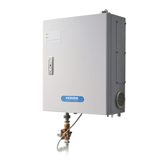
1 OVERVIEW OVERVIEW Outline This product is an automatic water-quality monitoring system that continuously measures water quality at the ending of the feed pipe of the water supply. The measurement items in the standard configuration are turbidity, color, residual chlorine. You can add conductivity and water temperature as optional measurement items by requesting them when ordering the product. -
Page 28: Part Names
1 OVERVIEW Part Names 1.2.1 Device Front Wiring inlet for input/ Wiring inlet for output terminal power connection Operation indicator (green) Lit when power is on Alarm indicator (red) Lights or blinks when an alarm occurs Locking handle Calibration tank tray Wiring inlet for Condensate pressure sensor... - Page 29 1 OVERVIEW Bottom - side connectors Wiring inlet Air opening Condensate Sample inlet outlet Drain Calibration inlet Abnormal sample inlet...
-
Page 30: Display
1 OVERVIEW 1.2.2 Display This section explains the contents of the display, using a typical screen as an example. The screen is equipped with a touch panel. Do not operate touch panel with wet finger or solid tools, such as pen or driver. The measurement items pH, conductivity and water temperature are optional and not ... - Page 31 1 OVERVIEW Screen example- Menu items are displayed ② ① ③ ④ Contents Examples ① Screen title DATA, I/O SETTING, etc. Screen page 1/2, 2/2, etc. ② number ③ Menu item DATA HISTORY, GRAPH, etc. ④ Next page Screen example- History and Information confirmation display ...
-
Page 32: Preparation
2 PREPARATION PREPARATION The following preparations are required before operating the device. See Installation Manual for installation, piping and wiring instructions. pH sensor installation: For measuring pH Conductivity sensor installation: For measuring conductivity (optional) Beads insertion: For cleaning the residual-chlorine sensor Cover for measuring cell Conductivity sensor... -
Page 33: Opening The Inner Door Of The Device
2 PREPARATION Opening the Inner Door of the Device 1. Push the bottom of the locking handle, and open the door while holding the handle. Locking handle 2. Make sure that the stop valve is closed and the power is OFF. 3. -
Page 34: Installing The Ph Sensor
2 PREPARATION Installing the pH Sensor 1. Make sure that the stop valve is closed and the power is OFF. 2. Remove the protective cap, liquid-junction washer, rubber cap and connector cap from the pH sensor. Connector cap Rubber cap Liquid-junction washer Protective cap 3. -
Page 35: Installing The Conductivity Sensor (Optional)
2 PREPARATION Installing the Conductivity Sensor (optional) 1. Make sure that the stop valve is closed and the power is OFF. 2. Loosen the screws and remove the cover. Screw Cover 3. Remove the cap from the conductivity sensor. Note Be careful not to lose the protective cap, as it will be used to store the sensor. -
Page 36: Insert Beads
2 PREPARATION Insert Beads 1. Make sure that the stop valve is closed and the power is OFF. 2. Loosen the screws and remove the cover. Screw Cover 3. Remove the sensor connector. Residual-chlorine sensor Retaining screw Enlarged view Sensor connector Residual-chlorine/conductivity cell Stop valve must be closed. -
Page 37: Operation
3 OPERATION OPERATION Starting the Device 1. Make sure that the device is correctly installed, according to the instructions in the Installation Manual. 2. Open the stop valve. A sample water will start to flow into the unit. Stop valve Open 3. - Page 38 3 OPERATION 5. Turn ON the power. Wait a while until the screen turns displays the MEASUREMENT screen. “WARM UP!” is displayed. “WARM UP!” is displayed until the temperature of the turbidity/color cell becomes stable (approximately 20 minutes). 6. Adjust the clock. Reference "5.7 Clock Adjustment"...
-
Page 39: Stopping The Device
3 OPERATION Stopping the Device 3.2.1 When stopping the device for a week or less 1. Turn off the power. 2. Close the stop valve. Stop valve must be closed. -
Page 40: When Stopping The Device For A Week Or More
3 OPERATION 3.2.2 When stopping the device for a week or more 1. Close the stop valve. 2. Start the water discharge operation action. Reference "5.11 Action" (page 105) 3. Turn the power OFF. 4. Open the inner door of the device. Reference "2.1 Opening the Inner Door of the Device"... -
Page 41: Restarting The Device
3 OPERATION Restarting the Device 3.3.1 When stopping the device for a week or less Follow the procedure in "3.1 Starting the Device" (page 11). 3.3.2 When stopping the device for a week or more 1. Remove the residual-chlorine sensor, insert beads, and then reinstall the sensor. Reference "7.4.3 Maintenance of the residual-chlorine sensor"... -
Page 42: Precautions For Measurements
3 OPERATION Precautions for Measurements Switch to maintenance mode when opening the inner door. Opening the inner door during measuring affects the values of turbidity and color measurements. Do the following to avoid abnormal output or alarms. Press [MAINTENACE] or [CAL.] and enter maintenance mode. ... -
Page 43: Calibration
4 CALIBRATION CALIBRATION Calibration is to adjust and match the measured and actual values and required to maintain accurate measurement and system performance. Calibration Patterns and Cycles Periodic calibration is required. Calibrate the values using any of the following patterns. Std. - Page 44 4 CALIBRATION Optional item Calibration cycles Measurement Procedure item Calibration pattern reference System Every 3 Abnormality Daily startup months occurrence Span calibration page 54 ◎ ◎ ◎ Individual zero-calibration ◎ Conductivity Adjustment calibration using sample water page 60 ...
- Page 45 4 CALIBRATION Calibration information Calibration Target Flow rate Description Turbidity It is normal zero calibration performed manually using zero Color Individual calibration solution for each measurement item. 50 mL/min Conductivity zero- Keep zero calibration solution in the calibration tank. Using calibration button operation, switch the liquid from the sample water to zero ...
- Page 46 4 CALIBRATION Calibration coefficient Calibration coefficient Contents Zero calibration coefficient Represents variation of the zero point. Span calibration coefficient Represents the inclination in response to sensitivity. Zero calibration coefficient Span calibration coefficient Ref. Ref. Min. Max. Unit Min. Max. Definition value value...
-
Page 47: Precautions For Calibration
4 CALIBRATION Precautions for Calibration Follow the correct order for calibration Perform calibration in the following order. Common zero calibration → pH → color → turbidity → conductivity (optional) → residual chlorine. Calibrating pH after color may cause measurement unstableness and calibration failure. Remove the residual-chlorine sensor before performing span calibration for color. - Page 48 4 CALIBRATION Tips for improving calibration accuracy Adjust the temperature of the calibrating solution to that of the sample water. Perform span calibration close to the upper limit of the measurement range. Use span calibration solution whose value stays within the range. When starting the system or after replacing the sensors, test run the device for more than ...
-
Page 49: Displaying The Calibration Screen
4 CALIBRATION Displaying the Calibration Screen 1. Press [CAL.] on the MEASUREMENT (main) screen. The CALIBRATION screen is displayed, displaying the calibration menu. [CAL.] 2. Press the button of the item to be calibrated. The calibration screen for the selected item is displayed. Example when the selected item is TURB. -
Page 50: Calibrating Ph
4 CALIBRATION Calibrating pH pH is optional. There are two calibration patterns for pH. See "4.1 Calibration Patterns and Cycles" (page 17) and select one of the patterns. Every month calibration using sample water is recommended to measure accurate pH value. 4.4.1 Individual zero calibration and span calibration <pH>... - Page 51 4 CALIBRATION 3. Press the ZERO VALUE button ([x.xx]) on the pHCAL. screen. The zero calibration value input screen is displayed. [x.xx] 4. Enter the zero calibration value using the numerical key pad and press [SET]. Input range: pH 2.00 to pH 12.00 [CLEAR]: Clears the whole value.
- Page 52 4 CALIBRATION 8. Adjust the flow rate to 50 mL/min using the flowmeter valve. Mark showing the 80 mL/min position 50 mL/min position (three gradations below 80 mL/min position) Flow rate reading position (top surface of the float) Valve Wait until the calibration is completed (10 minutes). [FIX]: Forcibly stops the calibration and updates it without waiting for automatic completion [STOP]: Stops the calibration The screen shows that the calibration is complete.
- Page 53 4 CALIBRATION Span calibration 1. Place the calibration tank with Span calibration solution beside the device. 2. Connect the tank to the calibration inlet of the device. 3. Press the SPAN VALUE button ([x.xx]) on the pHCAL. screen. The span calibration value input screen is displayed. [x.xx] 4.
- Page 54 4 CALIBRATION 8. Adjust the flow rate to 50 mL/min using the valve. Wait until the calibration is completed (10 minutes). [FIX]: Forcibly stops the calibration and updates it without waiting for automatic completion [STOP]: Stops the calibration The screen shows that the calibration is complete. 9.
-
Page 55: Adjustment Calibration Using Sample Water
4 CALIBRATION 4.4.2 Adjustment calibration using sample water <pH> [CAL.] [pH] MEASUREMENT screen CALIBRATION screen pHCAL. screen See "4.3 Displaying the Calibration Screen" (page 23). Preparation pH meter...1 Calibration procedure 1. Adjust the flow rate of the sample water to 80 mL/min using the valve. 2. - Page 56 4 CALIBRATION 6. Press [YES] to start sample water calibration. The screen shows that the calibration is in progress. Wait until the calibration is completed. The screen shows that the calibration is complete. 7. Press [YES]. The pH zero calibration coefficient is updated.
-
Page 57: Calibrating Color
4 CALIBRATION Calibrating Color There are three calibration patterns for color, not including automatic zero calibration. See "4.1 Calibration Patterns and Cycles" (page 17) and select one of the patterns. See "5.3 Automatic Zero Calibration" (page 82) for automatic zero calibration settings. Note Span calibration solution for color affects the residual-chlorine sensor. -
Page 58: Common Zero Calibration And Span Calibration
4 CALIBRATION 4.5.1 Common zero calibration and span calibration <color> [CAL.] [COL.] MEASUREMENT screen CALIBRATION screen COL. CAL. screen See "4.3 Displaying the Calibration Screen" (page 23). Preparation Rubber plug (included) Calibration tank…1 Span calibration solution…1 L (Pour the solution into the calibration tank) ... - Page 59 4 CALIBRATION Common zero calibration Note In common zero calibration, zero calibration is performed at the same time for the three measurement items: turbidity, color and residual chlorine. Therefore it is not necessary to perform zero calibration individually for turbidity, color and residual chlorine. In addition, you do not need to readjust the flow rate.
- Page 60 4 CALIBRATION Span calibration <color> Removing the residual-chlorine sensor 1. Stop the device (close the stop valve, discharge water and turn OFF the power). Reference " Stopping operation" (page 137). 2. Remove the residual-chlorine sensor. Reference " Removing the residual-chlorine sensor" (page 142). 3.
- Page 61 4 CALIBRATION 4. Press the SPAN VALUE button ([xx.x]) on the COL. CAL. screen. The span calibration value input screen is displayed. [xx.x] 5. Enter the span calibration value using the numerical key pad and press [SET]. Input range: 0.0 TCU to 20.0 TCU [CLEAR]: Clears the whole value.
- Page 62 4 CALIBRATION 9. Adjust the flow rate to 50 mL/min using the valve. Mark showing the 80 mL/min position 50 mL/min position (three gradations below 80 mL/min position) Flow rate reading position (top surface of the float) Valve Wait until the calibration is completed (10 minutes). [FIX]: Forcibly stops the calibration and updates it without waiting for automatic completion [STOP]: Stops the calibration The screen shows that the calibration is complete.
-
Page 63: Individual Zero Calibration And Span Calibration
4 CALIBRATION 4.5.2 Individual zero calibration and span calibration <color> [CAL.] [COL.] MEASUREMENT screen CALIBRATION screen COL. CAL. screen See "4.3 Displaying the Calibration Screen" (page 23). Preparation Calibration tank…2 Zero calibration solution…1 L (Pour the solution into one of the calibration tanks) ... - Page 64 4 CALIBRATION 4. Enter the zero calibration value using the numerical key pad and press [SET]. Input range: 0.0 TCU to 20.0 TCU [CLEAR]: Clears the whole value. [BACK]: Deletes the rightmost number of the value. The screen returns to the COL. CAL. screen. 5.
- Page 65 4 CALIBRATION The screen shows that the calibration is complete. 9. Press [YES]. The color zero calibration coefficient is updated. 10. Close the valve of the calibration tank. 11. Disconnect the calibration tank from the calibration inlet of the device. Span calibration - color ...
-
Page 66: Adjustment Calibration Using Sample Water
4 CALIBRATION 4.5.3 Adjustment calibration using sample water <color> [CAL.] [COL.] MEASUREMENT screen CALIBRATION screen COL. CAL. screen See "4.3 Displaying the Calibration Screen" (page 23). Preparation Color meter..1 Calibration procedure 1. Adjust the flow rate of the sample water to 80 mL/min using the valve. 2. - Page 67 4 CALIBRATION 6. Press [YES] to start sample water calibration. The screen shows that the calibration is in progress. Wait until the calibration is completed. The screen shows that the calibration is complete. 7. Press [YES]. The color zero calibration coefficient is updated.
-
Page 68: Turbidity Calibration
4 CALIBRATION Turbidity Calibration There are three calibrating patterns for turbidity, not including automatic zero calibration. See "4.1 Calibration Patterns and Cycles" (page 17) and select one of the patterns. See "5.3 Automatic Zero Calibration" (page 82) for automatic zero calibration settings. <Reference>... -
Page 69: Common Zero Calibration And Span Calibration < Turbidity
4 CALIBRATION 4.6.1 Common zero calibration and span calibration < turbidity > [CAL.] [TURB.] MEASUREMENT screen CALIBRATION screen TURB. CAL. screen See "4.3 Displaying the Calibration Screen" (page 23). Preparation Calibration tank…1 Span standard solution…1 L (Pour the solution into the calibration tank) ... - Page 70 4 CALIBRATION Common zero calibration Note In common zero calibration, zero calibration is performed at the same time for the three measurement items: turbidity, color and residual chlorine. Therefore it is not necessary to perform zero calibration individually for turbidity, color and residual chlorine. In addition, you do not need to readjust the flow rate.
- Page 71 4 CALIBRATION Span calibration <turbidity> 1. Place the calibration tank with span calibration solution beside the device. 2. Connect the tank to the calibration inlet of the device. Calibration solution tank Connect Stop valve must be closed. 3. Press the SPAN VALUE button ([x.xx]) on the TURB. CAL. screen. The span calibration value input screen is displayed.
- Page 72 4 CALIBRATION 6. Press [SPAN]. A confirmation screen is displayed asking whether to start calibration. 7. Press [YES] to start span calibration. The screen shows that the calibration is in progress. 8. Adjust the flow rate to 50 mL/min using the valve. Mark showing the 80 mL/min position 50 mL/min position (three gradations below 80 mL/min position) Flow rate reading position (top surface of the float)
- Page 73 4 CALIBRATION 12. Adjust the flow rate of the sample water to 80 mL/min using the valve. 13. Disconnect the calibration tank from the calibration inlet of the device.
-
Page 74: Individual Zero Calibration And Span Calibration
4 CALIBRATION 4.6.2 Individual zero calibration and span calibration <turbidity> [CAL.] [TURB.] MEASUREMENT screen CALIBRATION screen TURB. CAL. screen See "4.3 Displaying the Calibration Screen" (page 23). Preparation Calibration tank…2 Zero calibration solution…1 L (Pour the solution into one of the calibration tanks) ... - Page 75 4 CALIBRATION 4. Enter the zero calibration value using the numerical key pad and press [SET]. Input range: 0.00 NTU to 10.00 NTU [CLEAR]: Clears the whole value. [BACK]: Deletes the rightmost number of the value. The screen returns to the TURB. CAL. screen. 5.
- Page 76 4 CALIBRATION The screen shows that the calibration is complete. 9. Press [YES]. The turbidity zero calibration coefficient is updated. 10. Close the valve of the calibration tank. 11. Disconnect the calibration tank from the calibration inlet of the device. Span calibration <turbidity>...
-
Page 77: Adjustment Calibration Using Sample Water
4 CALIBRATION 4.6.3 Adjustment calibration using sample water <turbidity> [CAL.] [TURB.] MEASUREMENT screen CALIBRATION screen TURB. CAL. screen See "4.3 Displaying the Calibration Screen" (page 23). Preparation Turbidity meter...1 Calibration procedure 1. Measure turbidity of the prepared sample water using a turbidity meter other than this device's and calculate the value. - Page 78 4 CALIBRATION 5. Press [YES] to start sample water calibration. The screen shows that the calibration is in progress. Wait until the calibration is completed. The screen shows that the calibration is complete. 6. Press [YES]. The turbidity zero calibration coefficient is updated.
-
Page 79: Conductivity Calibration (Optional)
4 CALIBRATION Conductivity Calibration (Optional) Conductivity is optional. There are two calibration patterns for conductivity. See "4.1 Calibration Patterns and Cycles" (page 17) and select one of the patterns. <Reference> Making conductivity span calibration solution Reagent Amount (per 1 L) JIS-K8121 Potassium chloride 0.744 g... -
Page 80: Span Calibration
4 CALIBRATION 4.7.1 Span calibration <conductivity> [CAL.] [COND.] MEASUREMENT screen CALIBRATION screen COND. CAL. screen See "4.3 Displaying the Calibration Screen" (page 23). Preparation Calibration tank…1 Span standard solution…1 L (Pour the solution into the calibration tank) Used fluid tank (Install it so that used fluid goes into the tank) ... - Page 81 4 CALIBRATION 4. Enter the span calibration value using the numerical key pad and press [SET]. Input range: 0 µS/cm to 1000 µS/cm [CLEAR]: Clears the whole value. [BACK]: Deletes the rightmost number of the value. The screen returns to the COND. CAL. screen. 5.
- Page 82 4 CALIBRATION The screen shows that the calibration is complete. 9. Press [YES]. The conductivity span calibration coefficient is updated. 10. Close the valve of the calibration tank. 11. Open the stop valve. 12. Adjust the flow rate of the sample water to 80 mL/min using the valve. 13.
-
Page 83: Individual Zero Calibration
4 CALIBRATION 4.7.2 Individual zero calibration <conductivity> This is an open zero calibration. Perform calibration only when an abnormality occurs. [CAL.] [COND.] MEASUREMENT screen CALIBRATION screen COND. CAL. screen See "4.3 Displaying the Calibration Screen" (page 23). Calibration procedure 1. - Page 84 4 CALIBRATION 5. Remove the conductivity sensor from the residual chlorine/conductivity cell. Conductivity sensor Enlarged view Stop valve must be closed. Electric-conductivity sensor connector Installation location 6. Completely dry the electric conductivity sensor using paper, such as filter paper. Note Be careful not to scratch the sensor.
- Page 85 4 CALIBRATION 9. Enter 0 using the numerical key pad and press [SET]. [CLEAR]: Clears the whole value. [BACK]: Deletes the rightmost number of the value. The screen returns to the COND. CAL. screen. 10. Press [ZERO] on the COND. CAL. screen. A screen is displayed asking whether to start calibration.
-
Page 86: Adjustment Calibration Using Sample Water
4 CALIBRATION 4.7.3 Adjustment calibration using sample water <conductivity> [CAL.] [COND.] MEASUREMENT screen CALIBRATION screen COND. CAL. screen See "4.3 Displaying the Calibration Screen" (page 23). Preparation Conductivity meter...1 Calibration procedure 1. Measure electric conductivity of the prepared sample water using a conductivity meter other than the device's and calculate the value. - Page 87 4 CALIBRATION 5. Press [YES] to start sample water calibration. The screen shows that the calibration is in progress. Wait until the calibration is completed. The screen shows that the calibration is complete. 6. Press [YES]. The conductivity span calibration coefficient is updated.
-
Page 88: Calibrating Residual Chlorine
4 CALIBRATION Calibrating Residual Chlorine There are three calibrating patterns for residual chlorine, not including automatic zero calibration. See "4.1 Calibration Patterns and Cycles" (page 17) and select one of the patterns. It is necessary to prepare span calibration solution, however, it is difficult to prepare residual- chlorine solution with correct concentration and the concentration may change soon after preparation. - Page 89 4 CALIBRATION 4. Press [SAMPLE]. A confirmation screen is displayed asking whether to start calibration. 5. Press [YES] to start sample water calibration. The screen shows that the calibration is in progress. Wait until the calibration is completed. The screen shows that the calibration is complete. 6.
-
Page 90: Reference> Common Zero Calibration And Span Calibration
Put 35 L of commercial sodium hypochlorite solution (approximate) into a 1000 mL flask, add approximately 0.34 g of HORIBA pH 7 standard solution powder (Cat. No. 150-7), and then fill it with purified water up to the gauge line. Use this solution to determine the residual-chlorine value according to the procedure in JIS-K0101. - Page 91 4 CALIBRATION Common zero calibration Note In common zero calibration, zero calibration is performed at the same time for the three measurement items: turbidity, color and residual chlorine. Therefore it is not necessary to perform zero calibration individually for turbidity, color and residual chlorine. In addition, you do not need to readjust the flow rate.
- Page 92 2. Connect the tank to the calibration inlet of the device. Calibration tank Lift the calibration tank TW-150 More than 170 cm Calibration pipe Mount Drain pipe 3.
- Page 93 4 CALIBRATION 6. Press [SPAN]. A confirmation screen is displayed asking whether to start calibration. 7. Press [YES] to start span calibration. The screen shows that the calibration is in progress. 8. Adjust the flow rate to 80 mL/min using the valve. Mark showing the 80 mL/min position Flow rate reading position (top surface of the float) Valve...
-
Page 94: Reference> Individual Zero Calibration And Span Calibration
2. Connect the tank to the calibration inlet of the device. Calibration tank Lift the calibration tank TW-150 Calibration pipe Mount Drain pipe 3. Press the ZERO VALUE button ([x.xx]) on the FRC. CAL. screen. - Page 95 4 CALIBRATION 4. Enter the zero calibration value using the numerical key pad and press [SET]. Input range: 0.00 mg/L to 5.00 mg/L [CLEAR]: Clears the whole value. [BACK]: Deletes the rightmost number of the value. The screen returns to the FRC. CAL. screen. 5.
- Page 96 4 CALIBRATION The screen shows that the calibration is complete. 9. Press [YES]. The residual-chlorine zero calibration coefficient is updated. 10. Close the valve of the calibration tank. 11. Disconnect the calibration tank from the calibration inlet of the device. Span calibration <residual chlorine>...
-
Page 97: Calibrating Water Pressure
4 CALIBRATION Calibrating Water Pressure Water pressure is already calibrated before shipment, so additional calibration is unnecessary. The calibration procedure is given as a reference. Only when an abnormality occurs, check that the calibration coefficient is not far from the manually-analyzed value. 4.9.1 Adjustment calibration using sample water <water pressure>... - Page 98 4 CALIBRATION 5. Press [YES] to start sample water calibration. The screen shows that the calibration is in progress. Wait until the calibration is completed. The screen shows that the calibration is complete. 6. Press [YES]. The water pressure zero calibration coefficient is updated.
-
Page 99: Calibrating Water Temperature
4 CALIBRATION 4.10 Calibrating Water Temperature Water temperature is optional. Water temperature is already calibrated before shipment, so additional calibration is unnecessary. The calibration procedure is given as a reference. Only when an abnormality occurs, check that the calibration value is not far from the manually-analyzed value. 4.10.1 Adjustment calibration using sample water <water temperature>... - Page 100 4 CALIBRATION 5. Press [YES] to start sample water calibration. The screen shows that the calibration is in progress. Wait until the calibration is completed. The screen shows that the calibration is complete. 6. Press [YES]. The water temperature zero calibration coefficient is updated.
-
Page 101: Function
5 FUNCTION FUNCTION This device has many features, but in order to obtain the best performance, you must first configure the device. This section describes the functions and how to configure the settings. Function List Thoroughly learn the available functions to be able to configure and utilize them to meet your customers' needs. - Page 102 5 FUNCTION Function Detail Reference An alarm occurs when a malfunction occurs in sample water or "5.14 Alarm" (page Alarm the device. 119)
- Page 103 5 FUNCTION Displaying the maintenance item screen 1. Press [Mainte.] on the MEASUREMENT screen. The MAINTENANCE screen is displayed. 2. Select a maintenance item using buttons that are displayed in the MAINTENANCE screen. The MAINTENANCE item screen is displayed. MAINTENANCE screen operation button Screen name [SETTING]...
-
Page 104: Input/Output Settings
5 FUNCTION Input/Output Settings You can configure the following settings related to input/output. Setting Explanation Initial Setting Select the method for external input. EXT. I/O IN However, you must configure the handling of abnormal water sampling (5.2.1, page 79) separately.(page 92) ALG. -
Page 105: Setting Ext I/O In
5 FUNCTION 5.2.1 Setting EXT I/O IN [SETTING] [MAINTE.] [I/O] MAINTENANCE screen MEAS. screen SETTING1/2 screen I/O SETTING screen See " The I/O SETTING screen" (page 78). 1. Press the EXT I/O IN SETTING button on the I/O SETTING 1/2 screen. The EXT. - Page 106 5 FUNCTION 2. Select the items by using the buttons, and press [SET]. Item Explanation Initial Setting Hold and output the last measured value. If there is no last measured value when HOLD turning ON the power, the last value measured before turning OFF the power is held.
-
Page 107: Setting The Analog Output Level
5 FUNCTION 5.2.3 Setting the analog output level [MAINTE.] [SETTING] [I/O] MAINTENANCE screen MEAS. screen SETTING1/2 screen I/O SETTING 1/2 screen See " The I/O SETTING screen" (page 78). [ ] I/O SETTING 2/2 screen 1. Press the ANALOG OUTPUT LEVEL button on the I/O SETTING 2/2 screen. The ANALOG OUTPUT LEVEL screen is displayed. -
Page 108: Automatic Zero Calibration
5 FUNCTION Automatic Zero Calibration To secure a stable measurement value, zero calibration is performed automatically at a constant interval. Zero calibration is performed for turbidity, color and residual chlorine measurements. Zero-standard solution which filtered sample water is used. Note To perform the automatic zero calibration, set the EXT I/O IN to OFF. -
Page 109: Setting The Calibration Interval
5 FUNCTION 5.3.2 Setting the calibration interval [MAINTE.] [SETTING] [CALIBRATION SETTING] MAINTENANCE screen MEAS. screen SETTING1/2 screen [CALIBRATION SETTING] screen See " Displaying CALIBRATION SETTING screen" (page 82). 1. Press the CAL. INTERVAL button on the CALIBRATION SETTING screen. The CAL. -
Page 110: Auto Washing
5 FUNCTION Auto Washing If the windows of the measurement part of the turbidity and color sensors get dirty or form air bubbles on them, the correct values will not be measured. Auto washing is a function to regularly remove dirt and air bubbles from the measurement cell with a wiper so that measurements remain accurate. -
Page 111: Turning Auto Washing On And Off
5 FUNCTION 5.4.1 Turning auto washing ON and OFF [AUTO WASHING SETTING] [MAINTE.] [SETTING] MAINTENANCE screen MEAS. screen SETTING1/2 screen AUTO WASHING SETTING See " Displaying the AUTO WASHING SETTING screen" (page 84). 1. Press the AUTO WASHING button on the AUTO WASHING SETTING screen. The AUTO WASHING SETTING screen is displayed. -
Page 112: Setting The Standard Time
5 FUNCTION 5.4.3 Setting the STANDARD TIME [MAINTE.] [SETTING] [AUTO WASHING SETTING] MAINTENANCE screen MEAS. screen SETTING1/2 screen AUTO WASHING SETTING See " Displaying the AUTO WASHING SETTING screen" (page 84). 1. Press the STANDARD TIME button on the AUTO WASHING SETTING screen. The STANDARD TIME screen is displayed. -
Page 113: Auto Draining
5 FUNCTION Auto Draining Auto draining is a function to regularly remove dirt from the measurement cell and tubes with air bubbles and water draining so that measurements remain accurate. The following are available for auto drain. Setting Explanation Initial Setting ON/OFF: AUTO DRAIN Turns auto drain ON or OFF (5.4.1, page 85)... -
Page 114: Turning Auto Draining On And Off
5 FUNCTION 5.5.1 Turning auto draining ON and OFF [MAINTE.] [AUTO DRAIN] [SETTING] MAINTENANCE screen MEAS. screen SETTING1/2 screen AUTO DRAIN SETTING See " Displaying the AUTO DRAIN SETTING screen" (page 87). 1. Press the AUTO DRAIN button on the AUTO DRAIN SETTING screen. The AUTO DRAIN screen is displayed. -
Page 115: Setting The Standard Time
5 FUNCTION 5.5.3 Setting the STANDARD TIME [MAINTE.] [SETTING] [AUTO DRAIN SETTING] MAINTENANCE screen MEAS. screen SETTING1/2 screen AUTO DRAIN SETTING See " Displaying the AUTO DRAIN SETTING screen" (page 87). 1. Press the STANDARD TIME button on the AUTO DRAIN SETTING screen. The STANDARD TIME screen is displayed. -
Page 116: Setting The Hold Time
5 FUNCTION 5.5.5 Setting the HOLD TIME [MAINTE.] [SETTING] [AUTO DRAIN SETTING] MAINTENANCE screen MEAS. screen SETTING1/2 screen AUTO DRAIN SETTING See " Displaying the AUTO DRAIN SETTING screen" (page 87). 1. Press the HOLD TIME button on the AUTO DRAIN SETTING2/2 screen. The OUTPUT HOLD TIME screen is displayed. -
Page 117: Water Sampling
5 FUNCTION Water Sampling This function stores sample water when a measurement malfunction occurs. During the set water sampling time, sample water is obtained from the abnormal water sampling inlet with a flow rate of 80 mL/min. It is necessary to connect a container to obtain sample water from the inlet. -
Page 118: Setting The Sampling Check
5 FUNCTION 5.6.1 Setting the SAMPLING CHECK [MAINTE.] [SETTING] [SAMPLING SETTING] MAINTENANCE screen MEAS. screen SETTING1/2 screen SAMPLING SETTING See " Displaying the SAMPLING SETTING screen" (page 91). 1. Press the SAMPLING CHECK button on the SAMPLING SETTING screen. The SAMPLING CHECK screen is displayed. -
Page 119: Perform The Sampling Reset
5 FUNCTION 5.6.3 Perform the SAMPLING RESET [MAINTE.] [SETTING] [SAMPLING SETTING] MAINTENANCE screen MEAS. screen SETTING1/2 screen SAMPLING SETTING See " Displaying the SAMPLING SETTING screen" (page 91). 1. Press the SAMPLING RESET button on the SAMPLING SETTING screen. A screen confirming whether or not whether or not to reset the sampling time is displayed. -
Page 120: Clock Adjustment
5 FUNCTION Clock Adjustment [MAINTE.] [SETTING] MAINTENANCE screen SETTING 1/2 screen MEAS. screen SETTING 2/2 screen [ ] See " Displaying the maintenance item screen" 1. Press [CLOCK ADJUSTMENT] on the SETTING 2/2 screen. The CLOCK ADJUSTMENT screen is displayed. [CLOCK ADJUSTMENT] 2. -
Page 121: Lcd Setting
5 FUNCTION LCD Setting The following settings are available for the LCD. Setting Description Initial Setting BACK LIGHT TIME Adjusts the amount of time before the backlight of the LCD 10 min (the display) is dimmed when there is no operation. (page 95)... -
Page 122: Controlling Brightness
5 FUNCTION 5.8.2 Controlling brightness [LCD SETTING] button [MAINTE.] [SETTING] SETTING1/2 screen MAINTENANCE screen LCD SETTING MEAS. screen screen [ ] SETTING2/2 screen See " Displaying the LCD SETTING screen" (page 95). 1. Control the brightness using [ ] and [ ] on the LCD SETTING screen. -
Page 123: Touch Panel Adjustment
5 FUNCTION Touch Panel Adjustment Calibrate the screen position when a button other than the one that you pressed reacts, or the screen may act in an unexpected manner. [MAINTE.] [SETTING] SETTING1/2 screen MAINTENANCE screen MEAS. screen SETTING2/2 screen [ ] See "... -
Page 124: Measurement Settings
5 FUNCTION 5.10 Measurement Settings The following are available for configuring measurement settings. Measurement Setting Description Initial Setting item HIGH ALARM (5.14.6, page 123) LOW ALARM (5.14.7, page 124) See "5.14 Alarm" (page 119). UNIT HIGH ALARM Measurement (5.14.8, page 125) Items UNIT LOW ALARM (5.14.9, page 126)... - Page 125 5 FUNCTION Displaying the setting screens for each measurement item [MAINTE.] [MEAS. SETTING] MAINTENANCE screen MEAS. SETTING screen MEAS. screen See " Displaying the maintenance item screen" (page 77). 1. Press the button (the following example: [turbidity]) of any of the measurement items on the MEAS.SETTING screen.
-
Page 126: Setting The Coefficients
5 FUNCTION 5.10.1 Setting the COEFFICIENTS [MAINTE.] [MEAS. SETTING] [(Measurement item)] MEAS.SETTING MAINTENANCE screen [(Measurement item)] MEAS. screen screen MEAS.SETTING screen See " Displaying the setting screens for each measurement item" (page 99). Reference See "9.8 Evaluating Coefficients" (page 170). 1. -
Page 127: Setting The Range For Turbidity And Color
5 FUNCTION The screen returns to the COEFFICIENTS (a) SETTING screen for the appropriate measurement item. 4. Press [b=x.xxx]. The COEFFICIENTS (b) SETTING screen for the appropriate measurement item is displayed. 5. Enter the "b" value using the numerical key pad and press [SET]. Measurement item Input range All measurement items... -
Page 128: Correcting Color Using Turbidity
5 FUNCTION 5.10.3 Correcting color using turbidity This device can automatically correct the effect of turbidity on the color. However, the degree of the effect depends on the calibration solution and sample water, and the measurement value sometimes shifts with sample water. The turbidity coefficient corrects the measurement value. -
Page 129: Setting The Applied Voltage For Residual Chlorine
5 FUNCTION 5.10.4 Setting the applied voltage for residual chlorine [Residual chlorine] [MAINTE.] [MEAS. SETTING] FRC. MEAS. MEAS.SETTING MEAS. screen MAINTENANCE screen SETTING screen screen See " Displaying the setting screens for each measurement item" (page 99). 1. Press the APPLIED VOLTAGE button on the FRC. MEAS. SETTING 2/2 screen. The FRC. -
Page 130: Setting The Unit For Water Pressure
5 FUNCTION 1. Press the RANGE button on the FRC. MEAS. SETTING 2/2 screen. The FRC. RANGE screen is displayed. RANGE [0-2]/[0-5] 2. Select the button with the desired range, and press [SET]. Returns to the FRC. MEAS. SETTING screen 5.10.6 Setting the unit for water pressure [MAINTE.] [MEAS. -
Page 131: Action
5 FUNCTION 5.11 Action ACTION operation is a function that allows you execute the following operations by using the buttons on the LCD. ACTION Description AUTO WASHING Use wiper of the turbidity/color cells to wash the turbidity/color cells. Check automatically that the turbidity, color and the residual-chlorine sensor display zero when measuring the zero-solution and that the conductivity sensor (optional) drains the water in the cell and displays zero (zero opening). -
Page 132: Performing Action Operation
5 FUNCTION 5.11.1 Performing ACTION operation [MAINTE.] [ACTION] MAINTENANCE screen MEAS. screen ACTION screen See " Displaying the maintenance item screen" (page 77). The execution of ACTION operation is described using AUTO WASHING as an example. The execution is same for other items. ACTION executes when you press the button for an item on the ACTION screen. -
Page 133: Checking The Device Status
5 FUNCTION 5.12 Checking the Device Status The following items can be checked. TEMPERATURE Check the value of each compensation temperature sensor. (5.12.1, page 107) UNIT INFORMATION Check the model and ID of the device. The ID number is used when communicating over a serial connection, or in (5.12.2, page 107)... -
Page 134: Setting Id
5 FUNCTION 5.12.3 Setting ID 1. Press [UNIT INFORMATION] on the CHECK screen. The UNIT INFORMATION screen is displayed. The model number and ID information are displayed. [UNIT INFORMATION] 2. Press [ID]. The ID SETTING screen is displayed. 3. Enter the ID number using the numerical key pad and press [SET]. Input range: 0 to 99999999 [CLEAR]: Clears the whole value. -
Page 135: Analog Input Check
5 FUNCTION 5.12.4 Analog input check [MAINTE.] [CHECK] MAINTENANCE screen MEAS. screen CHECK screen See " Displaying the maintenance item screen" (page 77). 1. Press [ANALOG INPUT] on the CHECK screen. The ANALOG INPUT screen is displayed. The value of the analog input from each sensor is displayed. [ANALOG INPUT] 5.12.5 Analog output check [MAINTE.]... -
Page 136: Data Check
5 FUNCTION 5.13 Data Check The items for the data check are as follows. Data check item Description The past data of the measurement values can be confirmed DATA HISTORY numerically. Up to about 11 days of minute data (MIN) data can be saved, and up to about 13 months of hourly data (5.13.1, page 111)... -
Page 137: Displaying The Data History
5 FUNCTION 5.13.1 Displaying the data history [DATA] MEASUREMENT screen DATA screen See " Displaying Data for an Item" (page 110). 1. Press [DATA HISTORY] on the DATA 1/2 screen. The DATA HISTORY screen is displayed. The data history time and measurement value of each item are displayed. [DATA HISTORY] MIN.: Data for when the seconds on the clock were 00. -
Page 138: Deleting The Data History
5 FUNCTION 5.13.2 Deleting the data history [DATA] MEASUREMENT screen DATA screen See " Displaying Data for an Item" (page 110). 1. Press [DATA HISTORY] on the DATA 1/2 screen. The DATA HISTORY screen is displayed. [DATA HISTORY] 2. Press [DELETE]. A confirmation screen to delete the data is displayed. -
Page 139: Displaying A Graph
5 FUNCTION 5.13.3 Displaying a graph [DATA] MEASUREMENT screen DATA screen See " Displaying Data for an Item" (page 110). 1. Press [GRAPH] on the DATA 1/2 screen. The GRAPH screen is displayed, and the data history is displayed as a graph. [GRAPH] * This example is for the TURB. - Page 140 5 FUNCTION Changing the range of the vertical axis and horizontal axis of the graph 1. Press [SET]. The GRAPH SETTING screen is displayed. 2. Select the range in VERTICAL (HIGH), VERTICAL (LOW) or HORIZONTAL, and press [SET]. VERTICAL (HIGH)/ The value is the percentage of the range of measured values to display.
-
Page 141: Calibration History Check
5 FUNCTION 5.13.4 Calibration history check [DATA] MEASUREMENT screen DATA screen See" Displaying Data for an Item" (page 110). 1. Press [CALIBRATION HISTORY] on the DATA 1/2 screen. The CALIBRATION HISTORY screen is displayed. Maximum of 20 records of the calibration date or ZERO/SPAN CAL. are displayed in chronologic order by measurement item or zero/span. -
Page 142: Deleting The Calibration History
5 FUNCTION 5.13.5 Deleting the calibration history [CAL. HISTORY] [DATA] MEASUREMENT screen DATA screen CAL. HISTORY screen See"5.13.4 Calibration history check" (page 115). 1. Press [DELETE] on the CAL. HISTORY screen. A confirmation screen to delete the calibration history is displayed. 2. -
Page 143: Checking Flow Rate
5 FUNCTION 5.13.6 Checking flow rate [DATA] MEASUREMENT screen DATA screen See" Displaying Data for an Item" (page 110). 1. Press [CHECK FLOW RATE] on the DATA 1/2 screen. The CHECK FLOW RATE screen is displayed. [CHECK FLOW RATE] [RESET]: Resets the flow rate. -
Page 144: Transferring Data To A Cf (Compactflash) Card
5 FUNCTION 5.13.7 Transferring data to a CF (CompactFlash) card Transfers the data to a CF (CompactFlash) card. [DATA] MEASUREMENT screen DATA screen See " Displaying Data for an Item" (page 110). 1. Press [SAVE CF.] on the DATA 2/2 screen. A confirmation screen to copy the data is displayed. -
Page 145: Alarm
5 FUNCTION 5.14 Alarm You can activate an alarm when exceeding the specified measurement values for each measurement item. Reference "8.1 Alarm List" (page 148) The operations and settings for alarms are as follows. Item Description Checking an alarm You can check the current alarm. (5.14.1, page 120)... -
Page 146: Checking An Alarm
5 FUNCTION 5.14.1 Checking an alarm 1. Press [ALARM] on the MEASUREMENT (main) screen. The ALARM screen is displayed. The ALARM VALUE is displayed [ALARM] [RESET]: Resets the active alarm. 5.14.2 Canceling an alarm 1. Press [ALARM] on the MEASUREMENT (main) screen. The ALARM screen are displayed. -
Page 147: Checking The Alarm History
5 FUNCTION 5.14.3 Checking the alarm history [DATA] MEASUREMENT screen DATA screen See " Displaying Data for an Item" (page 110). 1. Press [ALARM HISTORY] on the DATA 1/2 screen. The ALARM 1/1 screen is displayed. ALARM, DATE/TIME, and ON/OFF are displayed. ON indicates that the alarm is active, and OFF indicates that the alarm has been cancelled. -
Page 148: Setting The Alarm Time
5 FUNCTION 5.14.5 Setting the ALARM TIME [SETTING] [MAINTE.] [I/O] MEAS. screen MAINTENANCE screen SETTING1/2 screen I/O SETTING screen See " The I/O SETTING screen" (page 78). 1. Press the ALARM TIME button on the I/O SETTING 2/2 screen. The ALARM TIME SETTING screen is displayed. -
Page 149: Setting The High Alarm
5 FUNCTION 5.14.6 Setting the HIGH ALARM [SETTING] [I/O] [MAINTE.] [(Measurement item)] MEAS. screen MAINTENANCE screen MEAS.SETTING screen MEAS.SETTING screen See " Displaying the setting screens for each measurement item" (page 99). 1. For each item to be set, press the button of the item on its MEAS. SETTING screen. Item to be set on the MEAS. -
Page 150: Setting The Low Alarm
5 FUNCTION 5.14.7 Setting the LOW ALARM [SETTING] [I/O] [MAINTE.] [(Measurement item)] MEAS. screen MAINTENANCE screen MEAS.SETTING screen MEAS.SETTING screen See " Displaying the setting screens for each measurement item" (page 99). 1. For each item to be set, press the button of the item on its MEAS. SETTING screen. Item to be set on the MEAS. -
Page 151: Setting The Unit High Alarm
5 FUNCTION 5.14.8 Setting the UNIT HIGH ALARM [SETTING] [I/O] [MAINTE.] [(Measurement item)] MEAS. screen MAINTENANCE screen MEAS.SETTING screen MEAS.SETTING screen See " Displaying the setting screens for each measurement item" (page 99). 1. For each item to be set, press the button of the item on its MEAS. SETTING screen. Item to be set on the MEAS. -
Page 152: Setting The Unit Low Alarm
5 FUNCTION 5.14.9 Setting the UNIT LOW ALARM [SETTING] [I/O] [MAINTE.] [(Measurement item)] MEAS. screen MAINTENANCE screen MEAS.SETTING screen MEAS.SETTING screen See " Displaying the setting screens for each measurement item" (page 99). 1. For each item to be set, press the button of the item on its MEAS. SETTING screen. Item to be set on the MEAS. -
Page 153: Input/Output
6 INPUT/OUTPUT INPUT/OUTPUT This device has interfaces for parallel input/output, analog output and RS-232C input/output on the top of the device. Use the I/O interfaces when you need to output information like warnings and measurement values, as well as when you need to perform remote operation. Analog Output When outputting to an external device, this device uses an analog current for output. - Page 154 6 INPUT/OUTPUT The mapping of terminals to measured values for analog output is as follows. The specification for the analog-current output is as follows. Signal Input/output Specifications classification circuit 4 mA to 20 mA DC, Current signal output Analog Signal Galvanically separated (COM common) ...
-
Page 155: Parallel Input/Output
6 INPUT/OUTPUT Parallel Input/Output 6.2.1 Parallel output This device contains the following outputs for the parallel interface. Terminal Item Description Output timing Signal ON when power is cut (closed circuit) Power failure 1, 2 Notifies of a power failure. Signal OFF when canceling the power failure (open circuit) Signal ON when in maintenance mode or Notifies that the device is in... -
Page 156: Parallel Input
6 INPUT/OUTPUT 6.2.2 Parallel input This device contains the following inputs for the parallel interface. After you enable outside input operation (See "5.2.1 Setting EXT I/O IN" (page 79) ), the following operations can be controlled with the inputs. Terminal Item Description Input timing... -
Page 157: Serial Input/Output (Rs-232C)
6 INPUT/OUTPUT Serial Input/Output (RS-232C) This device includes an RS-232C input/output as a standard feature. The specifications are as follows. For details on items such as commands, contact HORIBA Advanced Techno. JIS-C6361 Conformity Transmission format Baud rate: 19200 bps... -
Page 158: Storing The Data On A Cf (Compactflash) Card
6 INPUT/OUTPUT Storing the Data on a CF (CompactFlash) Card This device supports data transfer using a CF (compact flash) card. You can save internal data and transfer it to your PC and other devices. Use the provided CF (CompactFlash) card. Note The device supports the FAT file system. - Page 159 6 INPUT/OUTPUT AlmFRC Residual chlorine data alarm (bit-mapped) AlmPRESS Water pressure data alarm (bit-mapped) AlmPH pH data alarm (bit-mapped) AlmCOND Water temperature data alarm (bit-mapped) AlmTEMP Water temperature data alarm (bit-mapped) The data is given in hexadecimal. Replace a hexadecimal digit with its binary-coded form according to the following table.
- Page 160 6 INPUT/OUTPUT *2: Data alarm Convert the data as in *1. (MDATA.CSV) Same as HDATA.CSV. (ALMDATA.CSV) YY/MM/DD/HH:MM:SS Year/Month/Day/ Hour: Minute: Second AlmNo Alarm No. Alarm Status ON: 1 DataStat OFF: 0 (ZERO.CSV) [TURB]: Turbidity data [COLOR]: Color data [FRC]: Residual chlorine data [PRESS]: Water pressure data [PH]:...
-
Page 161: Maintenance
7 MAINTENANCE MAINTENANCE Perform calibration and regular checks of this device to maintain normal operation and performance. For calibration of this device, see "4 CALIBRATION" (page 17). Maintenance Items Maintenance item Maintenance cycle When to clean/replace Applicable Description 3 months 6 months Yearly As needed Sensors... - Page 162 7 MAINTENANCE Zero water filter Conductivity sensor (optional) pH sensor Residual-chlorine sensor Mesh filter Beads Stop valve must be closed.
-
Page 163: Stopping And Restarting Operation
7 MAINTENANCE Stopping and Restarting Operation Stopping operation 1. Close the stop valve. Stop valve must be closed. 2. Start the action for the water discharge operation. Reference "5.11 Action" (page 105) If water is not discharged properly, run sample water again and repeat the procedure from step . 3. -
Page 164: Connection Locations For The Sensor Connectors
7 MAINTENANCE Connection Locations for the Sensor Connectors The following figure shows the location of the sensor connectors. Sensor and cable with attached connector PRESS (Water pressure) TEMP (Water temperature) - Page 165 7 MAINTENANCE Connectors on the printed board Residual-chlorine Conductivity sensor sensor...
-
Page 166: Parts Maintenance And Replacement
7 MAINTENANCE Parts Maintenance and Replacement 7.4.1 Replacing the mesh filter 1. Make sure that the stop valve is closed, and the sample water is being discharged. Reference " Stopping operation" (page 137) 2. Remove the filter cap. You do not have to remove the tubes. 3. -
Page 167: Replacing The Filter Cartridge Of The Zero Water Filter
Filter cartridge Stop valve must be closed. 2. Insert a new filter cartridge, and screw on the cover. Note Replace filter cartridge prepared only for TW-150. Push the filter so that red line completely hide in the case. ... -
Page 168: Maintenance Of The Residual-Chlorine Sensor
7 MAINTENANCE 7.4.3 Maintenance of the residual-chlorine sensor The maintenance items and procedure are as follows. Maintenance item Procedure Polish the residual- Removing the residual-chlorine sensor → Polishing the residual-chlorine sensor → chlorine sensor Installing the residual-chlorine sensor Removing the residual-chlorine sensor → Replacing beads → Installing the residual- Replace beads chlorine sensor Replace the residual-... - Page 169 7 MAINTENANCE Polishing the residual-chlorine sensor When the sensitivity of the chlorine residual sensor declines, perform the following operation. 1. Remove the residual-chlorine sensor from the device. (" Removing the residual-chlorine sensor" (page 142)) 2. Prepare the attached sandpaper. 3.
-
Page 170: Replacing And Storing The Conductivity Sensor (Optional Unit)
7 MAINTENANCE 7.4.4 Replacing and storing the conductivity sensor (optional unit) 1. Loosen the screws and remove the cover. Screw Cover 2. Remove the conductivity sensor connector. Conductivity sensor Enlarged view Conductivity sensor connector Installation location Stop valve must be closed. 3. -
Page 171: Replacing And Storing The Ph Sensor
7 MAINTENANCE Storing a removed conductivity sensor Refill the attached protective cap with pure water, and attach it to the sensor. For details, see the operating manual for the sensor. Note Do not dry the conductivity sensor 7.4.5 Replacing and storing the pH sensor 1. - Page 172 7 MAINTENANCE 3. Remove the protective cap, liquid junction washer, rubber cap and connector cap from the new pH sensor. Connector cap Rubber cap Liquid junction washer Protective cap 4. Push the brown protrusion on the side of the sensor into the pH cell, as shown in the following figure, and turn the sensor to the left.
-
Page 173: Spare Parts
7 MAINTENANCE Spare Parts Name Specification Part number Calibration solution tank For calibration 3014039543 CF (CompactFlash) card 3014030160 Bottle for abnormal-water sampling PP, jar, 1 L 3014039544 Residual-chlorine electrode 3440-02C 3014039554 Beads 3200063518 Conductivity sensor 9382-02C 3014039224 pH sensor 6002 3014039223 Filter cartridge For zero water filter... -
Page 174: Troubleshooting
8 TROUBLESHOOTING TROUBLESHOOTING Alarm List Contact Alarm output Analog output Alarm Alarm Item Alarm Description Batch Batch ALG. OUT (ALARM) display history alarm alarm Cell temperature ○ adjustment ○ Lit ○ ○ ○ (All components) abnormality Cell temperature (WARMING UP adjustment warming ●... - Page 175 8 TROUBLESHOOTING Contact Alarm output Analog output Alarm Alarm Item Alarm Description Batch Batch ALG. OUT (ALARM) display history alarm alarm Concentration upper ● Blink ○ ○ ○ limit Concentration lower ● Blink ○ ○ ○ limit Concentration device ○ ○...
- Page 176 8 TROUBLESHOOTING Contact Alarm output Analog output Alarm Alarm Item Alarm Description Batch Batch ALG. OUT (ALARM) display history alarm alarm Concentration upper ● Blink ○ ○ ○ limit Concentration lower ● Blink ○ ○ ○ limit Concentration device ○ ○...
-
Page 177: Alarm Causes And Corrective Actions
8 TROUBLESHOOTING Alarm Causes and Corrective Actions Alarm Alarm Corrective action Item Cause Reference description (*: Manufacturer service required) Connection failure in heater Inspect heater temperature sensor temperature sensor or heater or heater connection.* Cell Failure in temperature Replace heater temperature temperature sensor in measurement cell sensor.*... - Page 178 8 TROUBLESHOOTING Alarm Alarm Corrective action Item Cause Reference description (*: Manufacturer service required) Air bubbles in turbidity/color Perform auto cleaning. page 105 cell Sample water abnormality Manually analyze sample water. Concentration Mismatched calibration upper limit Perform calibration. page 42 results Dirt in turbidity/color cell Clean turbidity/color cel.l*...
- Page 179 8 TROUBLESHOOTING Alarm Alarm Corrective action Item Cause Reference description (*: Manufacturer service required) Degradation or failure in Readjust or replace turbidity light turbidity light source (LED) source.* Detector failure Replace detector.* Light source Internal analog circuit board Replace internal analog circuit abnormality failure board (TW-ADC-01).*...
- Page 180 8 TROUBLESHOOTING Alarm Alarm Corrective action Item Cause Reference description (*: Manufacturer service required) Sample water abnormality Manually analyze sample water. Degradation in zero water Replace filter cartridge. page 141 filter Concentration Perform calibration. page 31 Mismatched calibration lower limit results Clean turbidity/color cell.* Dirt in turbidity/color cell...
- Page 181 8 TROUBLESHOOTING Alarm Alarm Corrective action Item Cause Reference description (*: Manufacturer service required) Degradation in zero water Replace filter cartridge. page 141 filter Mismatching calibration Replace calibration solution and page 31 solution reexecute calibration. Zero calibration Blockage in calibration Replace calibration solenoid solenoid valve valve.*...
- Page 182 8 TROUBLESHOOTING Alarm Alarm Corrective action Item Cause Reference description (*: Manufacturer service required) Sample water abnormality Manually analyze sample water. Mismatched calibration Perform calibration. page 62 results Concentration device upper Inappropriate applied voltage Set appropriate applied voltage. page 103 limit Electrode failure Replace residual-chlorine sensor.
- Page 183 8 TROUBLESHOOTING Alarm Alarm Corrective action Item Cause Reference description (*: Manufacturer service required) Rise in sample water Check sample water pressure. pressure Connection failure in Inspect pressure sensor Concentration pressure sensor connector connection.* upper limit Pressure sensor failure Replace pressure sensor.* Internal analog circuit board Replace internal analog circuit failure...
- Page 184 8 TROUBLESHOOTING Alarm Alarm Corrective action Item Cause Reference description (*: Manufacturer service required) Sample water abnormality Manually analyze sample water. Dirt in pH sensor Clean pH sensor. Connection failure in pH Inspect pH sensor connection.* page 138 Concentration sensor connector upper limit pH sensor expiration or Replace pH sensor.
- Page 185 8 TROUBLESHOOTING Alarm Alarm Corrective action Item Cause Reference description (*: Manufacturer service required) Sample water abnormality Manually analyze sample water. Dirt in conductivity sensor Clean conductivity sensor. Connection failure in Inspect conductivity sensor conductivity sensor page 138 Concentration connection.* connector upper limit Conductivity sensor...
- Page 186 8 TROUBLESHOOTING Alarm Alarm Corrective action Item Cause Reference description (*: Manufacturer service required) Mismatched calibration Reset calibration value and results reexecute calibration. page 53 Mismatching calibration Check calibration solution and solution reexecute calibration. Connection failure in Inspect conductivity sensor Span calibration conductivity sensor page 138...
- Page 187 8 TROUBLESHOOTING Alarm Alarm Corrective action Item Cause Reference description (*: Manufacturer service required) Sample water abnormality Check sample water temperature. Connection failure in water Inspect water temperature sensor temperature sensor connection.* connector Concentration lower limit Water temperature sensor Replace water temperature failure sensor.* Internal analog circuit board...
-
Page 188: Reference
9 REFERENCE REFERENCE Specifications Product name Water Distribution Monitor Type TW-150 (Standard configuration) turbidity, color, free residual chlorine, water pressure, pH Measurement items (Optional items) conductivity, water temperature *Measurements apply to tap water described in "Table 1 (page 164)". Measurement See "Table 2 (page 164)". - Page 189 9 REFERENCE Types: Power failure, batch alarm, maintenance Contents: Power failure…occurs when the power is turned off Batch alarm…cell temperature adjustment abnormality, temperature compensation abnormality, cell wiper abnormality internal communication abnormality, leak, battery abnormality, concentration upper limit concentration lower limit,concentration Contact output device upper limit, concentration device lower limit, light source abnormality zero calibration, span calibration, analyzer...
- Page 190 9 REFERENCE Flat and stable location with minimum vibrations or shocks No dust, mist or corrosive gas in the air Installation Under atmospheric pressure environment No direct sunlight Good ventilation Altitude 2000 m or lower ...
-
Page 191: Piping Flow
9 REFERENCE Piping Flow Standard Solenoid valve Measuring cell Zero calibration Measuring cell Air opening Mesh filter Turbidity Chlorine Pressure regulator Chromaticity Calibration inlet Flow meter Pressure sensor Sample inlet Capillary Stop valve Abnormal sample outlet Drain Measuring cell Sample water flow rate: 80 mL/min Solenoid valve Including optional items... -
Page 192: Turbidity Measurement
The thickness of the water layer is proportional to the density (concentration) of the turbid particles present in the water. The light used in TW-150 has a wavelength of 870 nm, and is compliant to ISO 7027-1:2016. Color Measurement The transmitted light measurement method is used in TW-150. This method measures the level of brownish-yellow in yellow-like colors shown in dissolution and colloidal materials contained in water at a wavelength of 375 nm using absorptiometry. -
Page 193: Residual Chlorine Measurement
9 REFERENCE Residual Chlorine Measurement Residual chlorine Residual chlorine is active chlorine remaining in water from the result of tap and pool water disinfection or chlorine treatment for sterilization and deodorization in the food industry. Active chlorine is used for industrial and household disinfectant or bleach. ... -
Page 194: Ph Measurement
9 REFERENCE Electrode cleaning This system adopts bead cleaning to maintain the electrode surface and measurement stable. pH Measurement pH measurement and temperature The temperature of the solution being inspected is an important parameter in the accurate measurement of pH. There are many possible sources of errors during measurement, such as the state of the solution junction potential, asymmetric potential, and standard solution pH concentration, but all of these items contain factors that change with the temperature. -
Page 195: Conductivity Measurement (Optional)
9 REFERENCE Types of pH standard solutions When measuring pH, the meter must be calibrated using a standard solution. There are several kinds of standard solutions. For normal measurement, two standard solutions (with a pH of 7 and 9) are sufficient to accurately calibrate the meter. pH 1.68 standard solution: Oxalate 0.05 mol/L tetra-potassium oxalate aqueous solution pH 4.00 standard solution: Phthalate... -
Page 196: Evaluating Coefficients
9 REFERENCE Each positive and negative ion in the solution will migrate toward the oppositely charged pole. The result is that current flows through the solution by means of ion conductivity. When this occurs, resistance R(expressed in ), is in inverse proportion to the area A (expressed in m of the pole plates, as is the case with metal and other conductors, and is proportional to the distance l (expressed in m) between the two pole plates. - Page 197 Headquarters 31, Miyanonishi-cho, Kisshoin Minami-ku, Kyoto, 601-8306 TEL:+81-75-321-7184 FAX:+81-75-321-7291...
Need help?
Do you have a question about the TW-150 and is the answer not in the manual?
Questions and answers