Table of Contents
Advertisement
Quick Links
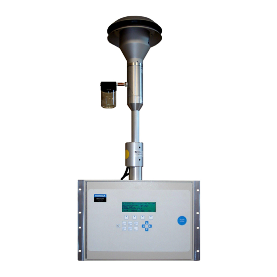
APDA-371
P
M
ARTICULATE
ONITOR
O
M
PERATION
ANUAL
APDA-371 Particulate Monitor Operation Manual - © Copyright 2008 HORIBA Europe GmbH. All Rights Reserved
worldwide. No part of this publication may be reproduced, transmitted, transcribed, stored in a retrieval system, or
translated into any other language in any form without the express written permission of HORIBA Europe GmbH.
Advertisement
Table of Contents

Subscribe to Our Youtube Channel
Related Manuals for horiba APDA-371


Summary of Contents for horiba APDA-371
- Page 1 APDA-371 Particulate Monitor Operation Manual - © Copyright 2008 HORIBA Europe GmbH. All Rights Reserved worldwide. No part of this publication may be reproduced, transmitted, transcribed, stored in a retrieval system, or translated into any other language in any form without the express written permission of HORIBA Europe GmbH.
-
Page 2: Table Of Contents
SETUP MENU DESCRIPTIONS CLOCK Screen ........................ 35 SAMPLE Settings Screen – Critical Information ............. 35 CALIBRATE Screen – Critical Information ..............37 EXTRA1 Screen ......................38 ______________________________________________________________________________________________________________________ HORIBA Europe GmbH, Julius-Kronenberg-Str. 9, D-42799 Leichlingen, : +49(0)2175-8978-0, : +49(0)2175-8978-50 Page 2... - Page 3 10.2 Series 500 Sensor Configurations ..................2 THEORY OF OPERATION and MATHEMATICAL ANALYSIS 11.1 Converting Data Between EPA Standard and Actual Conditions ........5 APDA-371 Audit Sheet Sample ______________________________________________________________________________________________________________________ HORIBA Europe GmbH, Julius-Kronenberg-Str. 9, D-42799 Leichlingen, Telefon: +49(0)2175-8978-0, Fax: +49(0)2175-8978-50 Page 3...
-
Page 4: Introduction
Ci ±15 Ci (microcurries), which is below the “Exempt Concentration Limit” as defined in 10 CFR Section 30.70 – Schedule A. The owner of a APDA-371 is not required to obtain any license in the United States to own or operate the unit. - Page 5 April, 2010 ______________________________________________________________________________________________________________________ The EPA designation applies to G, -1, G-1, and later APDA-371 PM10 Beta Attenuation Monitors, when used in conjunction with the following requirements. Users are advised that configurations that deviate from this specific description may not meet the applicable requirements of 40 CFR Parts 50 and 53.
-
Page 6: Usepa Equivalent Method
40 CFR Part 53 by the United States Environmental Protection Agency as of March 12, 2008. Designation Number: EQPM-0308-170 All of the following parameters and conditions must be observed when the APDA-371 is operated as a PM particulate monitor: •... -
Page 7: Apda-371 Specifications
Remove the unit and accessories from the shipping boxes and compare the received items to the packing list. Make sure you have all of the required items for the type of installation you plan to perform. ______________________________________________________________________________________________________________________ HORIBA Europe GmbH, Julius-Kronenberg-Str. 9, D-42799 Leichlingen, Telefon: +49(0)2175-8978-0, Fax: +49(0)2175-8978-50 Page 7... -
Page 8: Enclosure Selection
______________________________________________________________________________________________________________________ The APDA-371 is shipped with two white foam rings and a white plastic shim inside the front of the unit, which prevent the moving parts of the tape control assembly from being damaged in transit. Do not remove the foam rings until the APDA-371 is ready to be installed. -
Page 9: Mounting Options In A Walk-In Shelter
Mounting Options in a Walk-In Shelter When the APDA-371 is to be located in a walk-in shelter, the unit will have to be installed either in an equipment rack or on a bench-top. HORIBA recommends using an equipment rack when possible, as it does a better job of keeping the unit level and in the correct placement. -
Page 10: Installation Instructions In A Walk-In Shelter
Smart Heater: Before tightening the inlet tube in place, the BX-827 or BX-830 smart inlet heater (used on most APDA-371 units) must be installed on the tube. Pull the inlet tube up out of the inlet receiver, and pass the tube through the hole in the heater body (the cable end is the bottom). - Page 11 Support the tube in the best manner available. Temperature Sensor: Most APDA-371 units are supplied with a BX-592 (temperature) or BX-596 (temperature and pressure) sensor, which is attached to the inlet tube above the roof. The sensor cable must feed into the shelter to be attached to the APDA.
- Page 12 3236-02 3.2.4 SETUP OPERATE TEST TAPE With Medo vacuum pump or equivalent Mounting MET ONE INSTRUMENTS Bench or Rack Typical APDA-371 Installation in a walk-in shelter ______________________________________________________________________________________________________________________ HORIBA Europe GmbH, Julius-Kronenberg-Str. 9, D-42799 Leichlingen, : +49(0)2175-8978-0, : +49(0)2175-8978-50 Page 12...
- Page 13 OPERATE TEST TAPE Enclosure 7.0 ft (2.1 meters) with cyclone MET ONE INSTRUMENTS BX-126 Vacuum Pump or equivalent Typical APDA-371 Installation in a BX-902 mini enclosure ______________________________________________________________________________________________________________________ HORIBA Europe GmbH, Julius-Kronenberg-Str. 9, D-42799 Leichlingen, Telefon: +49(0)2175-8978-0, Fax: +49(0)2175-8978-50 Page 13...
- Page 14 CURRENT FLOW: 16.7 LPM STATUS: FIRMWARE: 3236-02 3.2.4 9.25” SETUP OPERATE TEST TAPE 120 VOLTS 3.5” MET ONE INSTRUMENTS FRONT BACK 17” 19” APDA-371 mounting dimensions ______________________________________________________________________________________________________________________ HORIBA Europe GmbH, Julius-Kronenberg-Str. 9, D-42799 Leichlingen, : +49(0)2175-8978-0, : +49(0)2175-8978-50 Page 14...
-
Page 15: Electrical Connections
Electrical Connections Each APDA-371 is factory configured to run on either 120 or 230 volt AC power. Your shelter must be wired for power to run the APDA, the pump, and any other AC powered devices such as computers, data loggers, other instruments, etc. - Page 16 ______________________________________________________________________________________________________________________ On previous versions of the kit, the Smart Heater assembly simply plugs directly into the back of the APDA-371, and power is supplied internally by the APDA. If the APDA is configured like this, then simply plug the heater cable directly into the mating green metal connector on the back of the APDA-371.
- Page 17 SW2 ON= 4-20mA CONTROL RS232 POLARITY POWER C1 NORMAL FAIL C2 REVERSE RS-232 POWER VOLTAGE OUTPUT CHASSIS PRINTER GROUNDS VACUUM POWER CURRENT OUTPUT APDA-371 back panel connections ______________________________________________________________________________________________________________________ HORIBA Europe GmbH, Julius-Kronenberg-Str. 9, D-42799 Leichlingen, Telefon: +49(0)2175-8978-0, Fax: +49(0)2175-8978-50 Page 17...
-
Page 18: Initial Setup Of Your Apda-371
Power On The APDA-371 has a power switch located on the back of the unit directly above the power cord. Verify that the unit is plugged in to the correct AC voltage, and that any electrical accessories are correctly wired before turn the unit on. -
Page 19: Filter Tape Loading
Filter Tape Loading A roll of filter tape must be loaded into the APDA-371 for sampling. One roll of tape should last more than 60 days under normal operation. It is important to have several spare rolls of tape available to avoid data interruptions. HORIBA recommends wearing lint-free cotton gloves when handling the tape. -
Page 20: Self-Test
An empty core tube MUST be installed on the left (take-up) reel hub. This provides a surface for the used tape to spool-up on. HORIBA supplies a plastic core tube to use with the first roll of tape. After that, you can use the empty core tube left over from your last roll to spool-up the new roll. -
Page 21: Initial Setup Settings Considerations
The self-test feature is located in the TAPE menu. Press the SELF TEST soft-key to start the test. The tests will take a couple of minutes, and the APDA-371 will display the results of each tested item with an OK or a FAIL tag. If all of the test items are OK, the status will show SELF TEST PASSED as shown in the drawing below. -
Page 22: Initial Leak Check And Flow Check
The unit will stop if the operator sets the Operation Mode to OFF or enters any of the SETUP or TEST menus. The APDA-371 will also stop itself if a non-correctable error is encountered, such as broken filter tape or failed air flow. -
Page 23: 3.11 The Normal Screen
The DOWN arrow can be used to set the Operation Mode from ON to OFF. This will stop the measurement cycle, but will not power-down the APDA-371. NOTE: If the operator sets the Operation Mode to OFF, or the unit stops itself... -
Page 24: 3.13 The Average Screen
(set by the MET SAMPLE value in the SETUP > SAMPLE menu - usually also 60 minutes). ______________________________________________________________________________________________________________________ HORIBA Europe GmbH, Julius-Kronenberg-Str. 9, D-42799 Leichlingen, : +49(0)2175-8978-0, : +49(0)2175-8978-50... -
Page 25: The Measurement Cycle
The One-Hour Cycle Timeline The APDA-371 is almost always configured to operate on 1-hour cycles. The unit has a real-time clock which controls the cycle timing. You will see from the following timeline that the unit makes two 8-minute beta measurements, and one 42-minute air sample, for a total of 58 minutes. -
Page 26: Automatic Span Check During The Cycle
The ABS value is unique to each APDA-371, and can be found on the calibration sheet. Sample Period Description The sample period is the time when the vacuum pump is pulling dust-laden air through the APDA-371. As the air enters the inlet, it first passes through the external PM head which has a screen to keep out bugs and debris, and uses inertia to separate out and trap particle larger than 10 microns in size. -
Page 27: Flow System And Flow Calibrations
APDA-371 Flow System Flow Type Descriptions The APDA-371 is designed to operate with an airflow rate of 16.7 liters per minute (lpm). This is important, because the particle separators (PM inlets, cyclones, and WINS impactors) require this flow rate in order to properly separate the correct sizes of particles from the air stream. -
Page 28: Leak Check Procedure
NIST traceable flow standards. This section describes the different types of flow control and regulation schemes used in the APDA-371. The unit can be set to any of three different flow types: Metered, Standard, or Actual (Volumetric), depending on the hardware available and the desired reporting conditions. -
Page 29: Leak Isolation And Nozzle Seal Methods
Leak Isolation and Nozzle Seal Methods Leaks can be further isolated using a soft rubber sheet with a ¼” hole in it, such as HORIBA part 7440. The filter tape can be removed and the rubber seal inserted with the hole centered under the nozzle. The seal allows the leak check to be performed as usual, but without any leakage through the filter tape. - Page 30 The figure below shows the difference between good and bad filter tape spots. The tape on the left is from a properly operated APDA-371 with a clean nozzle and vane. Notice the particulate spots have very crisp edges, are perfectly round, and are evenly distributed.
-
Page 31: Field Calibration Of Flow System - Actual (Volumetric) Flow Mode
Actual flow calibrations in units with older firmware: APDA-371 units with previous revisions of firmware (prior to Rev 3.0) have a different format in the TEST > FLOW menu, as shown below. These units are flow calibrated in the same way as described above, except that the flow calibration is performed at only a single point of 16.7 lpm, not a multi-point calibration as in new units. -
Page 32: Field Calibration Of Flow System - Epa Standard Flow Mode
Q values as described in section 5.8. The sections about the manual flow valve do not apply. Set the flow type back to STD when finished. ______________________________________________________________________________________________________________________ HORIBA Europe GmbH, Julius-Kronenberg-Str. 9, D-42799 Leichlingen, : +49(0)2175-8978-0, : +49(0)2175-8978-50 Page 32... -
Page 33: Field Calibration Of Flow System - Metered Flow Mode
1%. If not, repeat the entire flow calibration. After the flow is calibrated, use the flow adjustment knob on the rear of the APDA-371 and adjust the flow until the display reads 17.3 LPM. This level is within the specification of the PM particle separator, and will allow for filter loading in high concentration areas. -
Page 34: Setup Menu Descriptions
5. Turn the pump on in the TEST > PUMP menu and allow the flow to stabilize for 5 minutes. Then divide the displayed flow by CALNUM. 6. Adjust the flow adjustment knob on the back of the APDA-371 until the APDA flow reading equals 17.3 / CALNUM. Exit the TEST menu. -
Page 35: Clock Screen
(see Section 4.1 for a description of the measurement cycle). The APDA SAMPLE time must be set in response to the COUNT TIME value, since new versions of the APDA-371 allow the option of setting the count time to 4, 6, or 8 minutes. - Page 36 “range offset”. The new factory default value for OFFSET is now -0.015 mg. This causes the entire range of the APDA-371 to shift down slightly so that it can read from -0.015 to 0.985 mg, instead of measuring from 0 to 1.000 mg (assuming the RANGE is set to 1.000 mg).
-
Page 37: Calibrate Screen - Critical Information
CONC UNITS: This setting determines the concentration units which the APDA-371 displays and stores in memory. This can be set to ug/m3 (micrograms) or mg/m3 (milligrams) per cubic meter. This is a new option for the APDA-371. Past versions have always been set for mg/m3. Note: 1 mg = 1000 g. -
Page 38: Extra1 Screen
The K-factor is the factory-set slope correction (multiplier) for the APDA-371 concentration. The K-factor value is determined by dynamic testing of the APDA-371 in the factory smoke chamber. This will always be a value between 0.9 to 1.1. All of the stored and displayed data contains this correction. Warning: This is a unit-specific calibration value which may significantly affect the accuracy of the unit. -
Page 39: Errors Screen
ERRORS Screen This screen allows the operator the option of reporting APDA-371 errors with the analog output signal. This type of error indication is used when the operator is limited to a single voltage channel for particulate information, such as when the APDA is connected to certain types of data loggers. - Page 40 UP position when a measurement cycle starts. Photo sensor S9 is ON any time the latch is set. The APDA-371 has no way of unlatching and lowering the pinch rollers. It must be done manually.
-
Page 41: Password Screen
Split DELTAP: Not used. Reset Polarity: This tells the APDA-371 the incoming polarity of an external clock reset signal, if used. This signal is used to synchronize the APDA clock to an external data logger. NORM is normally open, INV is normally closed. -
Page 42: Heater Screen
The SETUP > HEATER screen is only visible if the HEATER CONTROL value in the SETUP > CALIBRATE menu is set to AUTO. This menu is used to configure the settings used by the APDA-371 to control the Smart Inlet Heater. The APDA uses an RH and temperature sensor located below the filter tape in the sample air stream to monitor the conditions of the air as it is being sampled. - Page 43 99 if not used. Datalog Delta-T: If YES is selected, the Delta-T values will be logged on channel 5 of the APDA-371. Select YES if you do not have any external sensors attached to channel 5. Note: The measured Delta-T may still be logged even if Delta-T control is set to NO.
-
Page 44: Maintenance, Diagnostics And Troubleshooting
Audit Sheet and Test Records The back of this manual contains a sample of a APDA-371 Audit Sheet. This is a test record which can be filled out as calibrations, checks, or audits are performed on the unit. The operator is encouraged to make copies of this sample ®... -
Page 45: Self-Test Feature
See Section 3.5 for a description of the self-test process. Power-Up Problems The APDA-371 must at least be able to power on before any further diagnosis can be performed. There are only a few possible reasons that the unit will fail to power up: •... - Page 46 • The nozzle o-ring eventually breaks down and needs to be replaced. Contact HORIBA for detailed instructions. Special shims are required to reinstall the nozzle. • The brass nozzle bushings may have grit in them. Remove the nozzle and clean the parts.
- Page 47 Check the photo sensors as described by section 7.16. • This is sometimes caused by misalignment of the “SHUTTLE” photo sensor or the interrupter flag on the end of shuttle beam inside the APDA. ______________________________________________________________________________________________________________________ HORIBA Europe GmbH, Julius-Kronenberg-Str. 9, D-42799 Leichlingen, Telefon: +49(0)2175-8978-0, Fax: +49(0)2175-8978-50 Page 47...
-
Page 48: Nozzle Component Replacement
Field BKGD Zero Background Tests The Background value is a correction offset for the concentration data collected by the APDA-371 (see section 6.3 for a description of the BKGD value). This value is factory calibrated for each unit under laboratory conditions, and is typically never changed for PM monitoring. - Page 49 Operation Manual HORIBA APDA-371 Particulate Monitor Date: April, 2010 ______________________________________________________________________________________________________________________ Typical zero background test results ______________________________________________________________________________________________________________________ HORIBA Europe GmbH, Julius-Kronenberg-Str. 9, D-42799 Leichlingen, Telefon: +49(0)2175-8978-0, Fax: +49(0)2175-8978-50 Page 49...
-
Page 50: Test Menu System
______________________________________________________________________________________________________________________ Test Menu System The following sub-sections provide information for performing diagnostic checks on the APDA-371 sub-systems using the TEST menus. Most of these tests will be used for troubleshooting purposes only and are not necessary on properly functioning units. The TEST menu system is accessed by the TEST soft-key from the main menu and is shown below. -
Page 51: Tape Test Menu
Use the up/down arrow keys to set the voltage anywhere from 0.000 to 1.000 volts in 0.100 increments. Measure the VOLT OUT +/- terminals on the back of the APDA-371 with a high quality voltmeter and verify that the actual voltage matches the APDA display value within ±0.001 volts at each point. Then attach the voltmeter to the input of your datalogger and repeat the test to verify that the correct voltages get to the input. -
Page 52: Interface Test Menu
INTERFACE Test Menu The TEST > INTERFACE screen is used to test the relay inputs and outputs on the back of the APDA-371. The two inputs (TELEM FAULT and EXT RESET) are tested by applying the appropriate signal to the terminals on the APDA, then verifying that the value on the screen changes in response. -
Page 53: Heater Test Menu
Older revisions of APDA firmware contain a different test screen for this sensor. ______________________________________________________________________________________________________________________ HORIBA Europe GmbH, Julius-Kronenberg-Str. 9, D-42799 Leichlingen, Telefon: +49(0)2175-8978-0, Fax: +49(0)2175-8978-50 Page 53... -
Page 54: Rh Test Menu - Filter Humidity Sensor
The APDA reading should change to match within +/- 4% RH. The RESET hot key can be used to revert to default calibrations and start over if difficulty is encountered. Older revisions of APDA firmware contain a different test screen for this sensor. ______________________________________________________________________________________________________________________ HORIBA Europe GmbH, Julius-Kronenberg-Str. 9, D-42799 Leichlingen, : +49(0)2175-8978-0, : +49(0)2175-8978-50 Page 54... -
Page 55: External Datalogger Interface System
This method is used because it is very rare for a concentration reading to exceed the range of the APDA-371. The digital data values stored in the APDA are unaffected and may be viewed with the display or by downloading. -
Page 56: Early Cycle Mode Description
Early Cycle Mode Description During a standard APDA-371 measurement cycle, the unit waits for the beginning of the new hour before it sets the analog output to represent the just-finished hour’s concentration. However, some types of dataloggers (such as ESC) must have the concentration value available before the new hour starts, or the data will be stored in the wrong hour. -
Page 57: Telemetry And Error Relays
Telemetry and Error Relays In addition to the analog output, input and output relay connections are provided on rear panel of the APDA-371 to allow the unit to be used with an external data logger in a synchronous mode of operation. The function of each input and output is described below. - Page 58 APDA-371 Back Panel Relay Connections TELEM FAULT N.V. Telemetry Fault Non-Voltage. This input can be used to signal the APDA-371 that the external telemetry system (datalogger) is not operational. This is a contact-closure input which must be activated for a minimum of 2-seconds. If activated, the APDA will continue to function and will log a “U”...
-
Page 59: Digital Datalogger Interfacing With The Apda-371
The most straight-forward way to accomplish digital datalogger interface with the APDA is to configure the printer output port as a fixed width data output as described in Sections 9.5 and 9.4. This causes the APDA-371 to output a single fixed-width string of data at the end of each sample hour without having to be prompted. - Page 60 HORIBA is often able to provide more technical information and support to help our customers develop effective programs for operating certain types of digital dataloggers with the APDA-371. In addition, we are always eager to hear about new ways that users have found to implement this type of interface. Contact HORIBA Technical Service.
-
Page 61: Rs-232 Serial Communications - Data Retrieval
Serial Port Connections and Settings The RS-232 serial port on the back of the APDA-371 handles data transfer and may also be used for instrument setup and operation status checks. The serial port may also be used with an optional modem for remote communications through a phone line (See Section 9.6). -
Page 62: System Menu File Descriptions
2. Open HyperTerminal. (Usually located in the Programs\Accessories\Communications directory). The program will ask you to type a name for the connection. Type “APDA-371” or a name of your choice, then click “OK”. 3. The “Connect To” window will open. Select COM1 (or another port if used) from the drop-down menu in the “Connect using:”... - Page 63 Display All Data This file will download a text file of all of the data stored in the APDA-371 memory, in the same format as the above example. Be sure to capture text (section 9.3) if downloading this file using HyperTerminal, as it can be fairly large.
- Page 64 ______________________________________________________________________________________________________________________ This file will contain text of all of the data stored by the APDA-371, since the last time the data was downloaded. Useful to avoid duplicate data in your database. A flag is set in the APDA indicating where the last download stopped.
- Page 65 (5 min averages of flow stats since last download) Example of a CSV Report of the "LAST DATA" record: The following example shows a CSV download of the last data record from the APDA-371. This file download does not reset the data pointer.
- Page 66 The flow statistics fields available in the CSV menu are described below. These files are not available except on APDA units configured as FEM PM units. A BX-596 sensor is required. ______________________________________________________________________________________________________________________ HORIBA Europe GmbH, Julius-Kronenberg-Str. 9, D-42799 Leichlingen, : +49(0)2175-8978-0, : +49(0)2175-8978-50 Page 66...
- Page 67 Display Last 100 Errors This file will contain the date, time, and a description of each of the last 100 errors logged by the APDA-371. This is a useful file for troubleshooting, and it will often be requested by HORIBA technicians if service is required.
-
Page 68: Printer Output Port
Printer Output Port The Printer port on the back of the APDA-371 is an output-only RS-232 serial interface which may be used with a serial printer or as a diagnostic output to a computer. The printer port output can be configured by using the “a” utility command through the main RS-232 port. -
Page 69: Flash Firmware Upgrades
Use the terminal program’s internal dialing command sequence to dial up the APDA-371. Verify the connection to the APDA-371 by pressing the <Enter> key until the command prompt asterisk (*) appears. If not, verify the cabling and communications settings. Once connected, the access to the APDA-371 is the same menu driven interface as used for the direct PC connection. -
Page 70: Accessories And Parts
10.1 Consumables, Replacement Parts, and Accessories The following parts are available from HORIBA for maintenance, replacement, service, and upgrades. If unsure about a part you need, please contact the Service department. Some of these parts require technical skills or special considerations before use or installation. - Page 71 O-Ring, Nozzle 720066 720069 O-Ring, Inlet Receiver, 2 required O-Ring Kit, APDA 9122 Pump Tubing, Clear, 10mm O.D., 6.5mm I.D. 960025 Polyurethane, 25 foot roll standard ______________________________________________________________________________________________________________________ HORIBA Europe GmbH, Julius-Kronenberg-Str. 9, D-42799 Leichlingen, Telefon: +49(0)2175-8978-0, Fax: +49(0)2175-8978-50 Page 71...
- Page 72 Circuit Board, CPU 3230-8 3250-1 Circuit Board, Interface 3260-1 Circuit Board, Rear Panel Interconnect Fuse, APDA-371, 3.15A, 250V, 5x20mm, 2 Req’d 590811 Motor, with gear box, 4 RPM 8105-1 Motor, with gear box, 10 RPM 8106-1 Power Supply, 115 VAC, 60 Hz...
- Page 73 BX-822 Inlet Tube Extension Kit, 4 foot, with coupler and tube Inlet Tube Extension Kit, 8 foot, with coupler and tube BX-823 8112 Inlet Tube, Aluminum, 8 foot length standard Inlet Tube, Custom Length 8112-X Dash number is length in feet, 8’ max per tube Smart Heater Option, 115 VAC BX-827 Smart Heater Option, 230 VAC...
-
Page 74: Series 500 Sensor Configurations
Series 500 Sensor Configurations The APDA-371 has six channels of inputs available on the back of the unit for data logging external sensors. The 500 Series sensors are a set of meteorological sensors designed for direct compatibility with these channels. The sensors each have an auto-identification (ID) signal wire with a voltage unique to that particular type of sensor. - Page 75 March 2007. Mounting: The 500 series sensors typically mount near the top of the APDA-371 inlet tube with a short cross-arm and related hardware. The sensors may also be mounted to a nearby tripod, such as HORIBA model 905.
-
Page 76: Theory Of Operation And Mathematical Analysis
Lambert-Beers Law is an idealization of what is actually observed, Equation 1 is also an idealized simplification of the true processes occurring meant to simplify the corresponding mathematics. However, experimental measurement shows that in properly designed monitors, such as the APDA-371, the use of this equation introduces no substantial error. -
Page 77: Converting Data Between Epa Standard And Actual Conditions
/Q) may be minimized by properly controlling the flow of the instrument. For APDA- 371 units with a manual flow valve, this value is on the order of ± 3%. For APDA-371 units equipped with the mass flow /Q) decreases to ± 1%. - Page 78 303 K and the average pressure was 720 mmHg. * (P ) * (T = 27 * (720/760) * (298/303) = 27 * 0.9474 * 0.9835 = 25.1 µ µ µ µ g ______________________________________________________________________________________________________________________ HORIBA Europe GmbH, Julius-Kronenberg-Str. 9, D-42799 Leichlingen, : +49(0)2175-8978-0, : +49(0)2175-8978-50 Page 6...
- Page 79 Operation Manual HORIBA APDA-371 Particulate Monitor Date: April, 2010 ______________________________________________________________________________________________________________________ APDA-371 Audit Sheet Model: APDA-371 Serial Number: Audit Date: Audited By: Flow Audits Flow Reference Standard Used: Model: Serial No: Calibration Date: Temperature Standard Used: Model: Serial No: Calibration Date:...
- Page 80 Datalog RH COUNT TIME HEATER Delta-T Control FLOW RATE Delta-T Setpoint CONC TYPE Errors Datalog Delta- Last 6 Errors in APDA-371 Error Log Error Date Time Error Date Time Audit Notes: ______________________________________________________________________________________________________________________ HORIBA Europe GmbH, Julius-Kronenberg-Str. 9, D-42799 Leichlingen, : +49(0)2175-8978-0,...
- Page 81 Operation Manual HORIBA APDA-371 Particulate Monitor Date: April, 2010 ______________________________________________________________________________________________________________________ OPERATOR NOTES: APDA-371-9800 REV F Page 9...
Need help?
Do you have a question about the APDA-371 and is the answer not in the manual?
Questions and answers