Table of Contents
Advertisement
Advertisement
Table of Contents

Related Manuals for horiba OPSA-150


Summary of Contents for horiba OPSA-150
- Page 1 Organic Pollutant Monitor OPSA-150 Instruction Manual CODE:GZ0000551319...
- Page 2 HORIBA Advanced Techno Co., Ltd. warrants that the Product shall be free from defects in material and workmanship and agrees to repair or replace free of charge, at option of HORIBA Advanced Techno Co., Ltd., any malfunctioned or damaged Product attributable to responsibility of HORIBA Advanced Techno Co., Ltd.
- Page 3 Regulations EU regulations Conformable standards This equipment conforms to the following standards: EMC: EN61326-1 Class A, Industrial electromagnetic environment Safety: EN61010-1 RoHS: EN50581 9. Industrial monitoring and control instruments Warning: This is a Class A product. In a domestic environment this product may cause radio interference in which case the user may be required to take adequate measures.
- Page 4 FCC rules Any changes or modifications not expressly approved by the party responsible for compliance shall void the user's authority to operate the equipment. Warning This equipment has been tested and found to comply with the limits for a Class A digital device, pursuant to part 15 of the FCC Rules.
- Page 5 For Your Safety Hazard classification and warning symbols Warning messages are described in the following manner. Read the messages and follow the instructions carefully. Hazard classification This indicates an imminently hazardous situation which, if not avoided, will result in death or serious injury. This is to be limited to the most extreme situations.
- Page 6 Safety precautions This section provides precautions for using the product safely and correctly and to prevent injury and damage. The terms of DANGER, WARNING, and CAUTION indicate the degree of imminency and hazardous situation. Read the precautions carefully as it contains important safety messages.
- Page 7 Product Handling Information Operational precautions Use of the product in a manner not specified by the manufacturer may impair the protection provided by the product. And it may also reduce product performance. Exercise the following precautions: Use the unit in the temperature range shown in the general specifications. ...
- Page 8 This is the English translation of an original Japanese document. Documents related to this product The following documents are related to this product. Instruction manual for OPSA-150 (this manual) This volume contains information about necessary work and procedures for daily measurement operations.
-
Page 9: Table Of Contents
Contents Overview ......... Introduction . - Page 10 TURB (turbidity) Span Calibration ......4.5.1 How to Prepare the Calibration Solution ..... . 4.5.2 TURB (turbidity) Span Calibration .
- Page 11 5.9.2 Alarm Stop ..........5.9.3 Alarm History Check .
- Page 12 Measurement Principle ....... . . 105 TURB (turbidity) Measurement ......106 How to Calculate the COD Conversion Factor .
-
Page 13: Overview
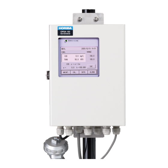
1 Overview Overview Introduction The OPSA-150 Organic Pollutant Monitor provides continuous measurement of organic pollutants and ultraviolet (253.7 nm) absorption in industrial wastewater, river water, and saltwater. A typical continuous measuring device for drainage water or environmental water cannot provide stable measurement values over long periods of use due to generation of drift from the deteriorated light source/detector or cell contamination from the sample water. -
Page 14: Description Of Parts
1 Overview Description of Parts 1.2.1 Unit Front view and side view Roof (optional) Control unit Display Door No Sample Float switch Analyzer unit Overflow tank Measuring tank Base Left side view Front view Note The pole stand and the base illustrated are typical examples. Appearance and size may vary depending on the specifications. - Page 15 1 Overview Inside of the control unit Display (Touch panel) Power/alarm LED Power switch Maintenance switch Fuse CF card insertion slot CF CARD Signal terminals Connectors for the analyzer unit AC power terminals...
-
Page 16: Display
1 Overview 1.2.2 Display This section describes the parameters shown on a typical display: The display is touch panel. Do not press buttons with wet hands, or a sharp object such as a pen tip or a screwdriver. If no buttons are pressed for a certain period of time, the backlight turns OFF. ... - Page 17 1 Overview Example of display - Displaying items to be selected ① ② ③ Description Display example ① Title of display MAINTENANCE, SETTING, etc. ② Selection keys SETTING, MEAS.SETTING, etc. ③ Switching keys CLOSE, etc. Example of display - Displaying history and other information ...
-
Page 18: Installation
2 Installation Installation Contact for Installation Manufacturer: HORIBA Advanced Techno Co., Ltd. 31, Miyanonishi-cho, Kisshoin Minami-ku, Kyoto 601-8306, Japan Conditions for Installation The unit is weather-proofed for outdoor installation; however, do not install the unit in places subject to direct sunlight. -
Page 19: Installation Method
2 Installation Installation Method Assemble the base, measuring tank, overflow tank and control unit as guided in the working instruction separately supplied. Secure the base with the reference bolts. Roof (optional) Control unit Overflow tank Analyzer unit Measuring tank Wing nuts (4) Base さ... -
Page 20: Piping Configuration
2 Installation Piping Configuration Insulate the unit to protect against frozen pipes in the cold weather. Drain piping should be as short as possible in order not to create the backpressure. Make the drain cock discharge the air in order to prevent water from being blocked (rising pipes cannot be used). - Page 21 2 Installation Note Each piping diameter above is determined to go with the respective piping sockets of the OPSA- 150. If the measuring unit is installed in an area far from the water sampling point and drainage point, each piping diameter should be larger than that indicated above. Ensure that the waste water piping, overflow piping (1) and (2), and drain piping have sufficient ...
-
Page 22: Wiring
2 Installation Wiring WARNING Maintain ground to avoid electric shock. 2.5.1 Grounding Class D grounding should be performed. Make sure to ground to the grounding bolt. Position of grounding bolt Note The pole stand and the base illustrated are typical examples Appearance and size may vary depending on specifications. -
Page 23: Connecting Analyzer Unit To Control Unit
2 Installation 2.5.4 Connecting Analyzer Unit to Control Unit Run the cable connectors of analyzer unit through the cable clamps at the lower left of control unit case. Connect the connectors of the analyzer unit to CN1 and CN2 at the lower left of the ... -
Page 24: Operation
3 Operation Operation Preparation for Operation 1. Ensure that the unit is installed properly according to "2 Installation" (page 6). 2. Remove the lid of the overflow tank. 3. Remove the analyzer unit if the unit is already set to the measuring tank. Note When removing from the measuring tank, put the analyzer unit on a flat surface to prevent it from falling. -
Page 25: Starting Operation
3 Operation Starting Operation 1. Turn the POWER switch ON. The MEAS. screen appears after a while. “WARM UP!” is indicated. Note When the power is turned ON, the motor for analyzer unit wipers starts operation at low speed. Some noises and vibrations may be generated when the motor starts. -
Page 26: Shutting Down
3 Operation Shutting Down 3.3.1 For Shut Down within 7 Days 1. Turn ON the maintenance switch. 2. Turn OFF the POWER switch. 3.3.2 For Shut Down over 7 Days 1. Close all the valves (V-1 to V-4). 2. Turn ON the maintenance switch. 3. -
Page 27: Calibration
4 Calibration Calibration Calibration is the adjustment so that the value indicated by the unit corresponds to the actual value. It is necessary to obtain measurements of high accuracy and maintain the performance of the unit. Calibration Pattern and its Cycle It is necessary to perform the calibration periodically. -
Page 28: Notes Regarding Calibration
4 Calibration Notes Regarding Calibration Perform the calibration in the order of “Common zero calibration," "Common span calibration,” and “TURB Span calibration.” If the calibration coefficient exceeds the specified range during the calibration, an error occurs and the calibration value is not updated. The previous calibration value remains. Use distilled water for the common zero calibration solution. -
Page 29: Calibration Screen Display
4 Calibration Calibration Screen Display 1. Press [CAL] on the MEAS. screen (main screen). The CALIBRATION screen that shows the calibration menu is displayed. [CAL.】 2. Press the measurement item to be calibrated on the CALIBRATION screen. The CALIBRATION screen for each measurement item is displayed. Example when the calibration item is UV/VIS: Calibration item: [UV/VIS]... -
Page 30: Calibration Of Uv/Vis
4 Calibration Calibration of UV/VIS There are three kinds of calibration method for UV/VIS: common zero calibration, common span calibration, and individual span calibration. Reference "4.1 Calibration Pattern and its Cycle" (page 15). 4.4.1 How to Prepare Calibration Solution Use distilled water for the zero calibration solution, and exclusive calibration solution for the common span calibration solution. - Page 31 4 Calibration 1. Drain the solution remaining in the top of ampoule to the bottom part. Drain the solution remaining in the top of the ampoule as much as possible by flicking with a finger. 2. Make a cut line on the ampoule with a cutter knife, knife or other sharp object. Make a cut line all the way around the ampoule.
- Page 32 4 Calibration How to prepare span calibration solution of acid potassium phthalate standard solution (standard solution for UV calibration) Normally calibration with the common span calibration solution is available; also, UV calibration with acid potassium phthalate is possible. Preparation Acid potassium phthalate: using the special grade chemicals, dried for 1 hour at a temperature of 120°C, and cooled in desiccators...
-
Page 33: Common Zero Calibration
4 Calibration 4. Pour the solution in the 1 L beaker into the 2 L measuring flask, add zero solution to the gauge line, and shake to dissolve the solution. 4.4.2 Common Zero Calibration [CAL.] [UV/VIS] MEAS. screen CALIBRATION screen UV/VIS CAL. - Page 34 4 Calibration 5. Clean the cell unit of the analyzer unit. If there is any extraneous matter around the cell, remove it. Next, dip the cell unit in the plastic bucket to remove contamination. Dip the cell unit in the water and shake it from side to side and up and down to remove contamination.
- Page 35 4 Calibration Note The decimal place of input range varies according to the setting in "5.5.2 Setting of Decimal Place for each Component" (page 48). [CLEAR]: Clears all input numeric values. [BACK]: Clears the rightmost number. 9. Press the button for [ZERO VALUE] for VIS on the UV/VIS CAL. screen. 10.
-
Page 36: Common Span Calibration
4 Calibration 4.4.3 Common Span Calibration [CAL.] [UV/VIS] MEAS. screen CALIBRATION screen UV/VIS CAL. screen Refer to "4.3 Calibration Screen Display" (page 17) Perform the common span calibration after finishing the common zero calibration. Preparation Calibration tank: Span calibration solution: 2 L (measuring flask) Cleaning bottle: Light shielding glasses:... - Page 37 4 Calibration 4. Pour the residual common span solution into the cleaning bottle. Residual common span solution Cleaning bottle When performing span calibration, the calibration work can be performed smoothly if the preparation through step 4. is performed together with the preparation for the common zero calibration.
- Page 38 4 Calibration 8. Enter the concentration value of compounded span calibration solution with the numeric keypad, and press [SET]. Input range: 0.000 Abs to 5.000 Abs or 0.0 m to 500.0 m The screen returns to the UV/VIS CAL. screen. Note The decimal place of the input range varies according to the setting in "5.5.2 Setting of Decimal ...
-
Page 39: Individual (Uv) Span Calibration
4 Calibration 4.4.4 Individual (UV) Span Calibration [CAL.] [UV/VIS] MEAS. screen CALIBRATION screen UV/VIS CAL. screen Refer to "4.3 Calibration Screen Display" (page 17) Perform the individual (UV) span calibration after finishing the common span calibration. Preparation Calibration tank: Span calibration solution: 2 L (measuring flask) Cleaning bottle:... - Page 40 4 Calibration 4. Pour the residual individual span solution into the cleaning bottle. Residual individual (UV) span solution Cleaning bottle When performing span calibration, the calibration work can be performed smoothly if the preparation through step 4. is performed together with the preparation for the common zero calibration.
- Page 41 4 Calibration 8. Enter the concentration value of compounded span calibration solution with the numeric keypad, and press [SET]. Input range: 0.000 Abs to 5.000 Abs or 0.0 m to 500.0 m The screen returns to the UV/VIS CAL. screen. Note The decimal place input range varies according to the setting in "5.5.2 Setting of Decimal place ...
-
Page 42: Turb (Turbidity) Span Calibration
4 Calibration TURB (turbidity) Span Calibration Only the span calibration is applied to the calibration method for TURB. Perform TURB span calibration after performing the common zero calibration and the common span calibration of UV/VIS. Refer to "4.1 Calibration Pattern and its Cycle" (page 15). TURB span calibration is to obtain the turbidity coefficient converted from the light absorption of VIS. - Page 43 4 Calibration Kaolin standard solution (for 100 mg/L) After shaking up the concentrated kaolin standard solution (1000 mg/L) which is commercially available or compounded by following the above mentioned table, immediately take the 200 mL and pour into the 2000 mL measuring flask and add tap water up to the gauge line. Note Make sure to use the pure water to dilute the TURB span calibration solution.
-
Page 44: Turb (Turbidity) Span Calibration
4 Calibration 4.5.2 TURB (turbidity) Span Calibration [CAL.] [UV/VIS] MEAS. screen CALIBRATION screen TURB CAL screen Refer to "4.3 Calibration Screen Display" (page 17) Perform the TURB span calibration after finishing the common zero calibration and the common span calibration. Preparation ... - Page 45 4 Calibration 4. Pour the residual TURB span solution into the cleaning bottle. Residual TURB span solution Cleaning bottle 5. Take the analyzer unit from the calibration tank, and clean the cell unit using the TURB span solution in the cleaning bottle. Clean the cell unit using the TURB span solution in the cleaning bottle.
- Page 46 4 Calibration 8. Enter the concentration value of compounded TURB calibration solution with numeric keypad, and press [SET], Input range: 0.00 to 9999.99 The screen returns to the TURB. CAL. screen. Note The decimal place of input range varies according to the setting in "5.5.2 Setting of Decimal Place for each Component"...
-
Page 47: Functions
5 Functions Functions This unit has various functions. It is necessary to set various conditions to utilize these functions fully. This chapter describes the functions and the setting procedures. MEAS. (Measurement) Screen The main screen displayed at the start when the power in ON. Measurement screen contains two screens;... -
Page 48: Maintenance Screen Display
5 Functions Maintenance Screen Display 1. Press [MAINT.] on the MEAS. screen. The MAINTENANCE screen appears. 2. Select the maintenance item with buttons displayed on the MAINTENANCE screen. The MAINTENANCE screen for each item appears. MAINTENANCE screen operation buttons Displayed screen [SETTING] SETTING screen [MEAS. -
Page 49: Maintenance - Setting
5 Functions Maintenance - Setting All maintenance settings are performed here. 5.4.1 Signal Allocation [SIGNAL INPUT SETTING] [MAINT.] [SETTING] SIGNAL ALLOCATION screen MEAS. MAINTENANCE SETTING 1/2 (1/3) screen screen screen Refer to "5.3 Maintenance Screen Display" (page 36). The output terminals for analog output and contact output are allocated here. 1. - Page 50 5 Functions 2. Output signal is allocated. Setting item Description Initial setting ANALOG OUTPUT A1 Sets to output either one of the following measurement component to the analog output ANALOG OUTPUT A2 TURB terminal from A1 to A3. Setting range: ANALOG OUTPUT A3 UV-VIS UV, VIS, UV-VIS, COD, TURB, NONE...
-
Page 51: Signal Input Setting
5 Functions 5.4.2 Signal Input Setting [MAINT.] [SIGNAL INPUT SETTING] [SETTING] SIGNAL INPUT SETTING screen MEAS. MAINTENANCE SETTING 1/2 screen screen screen Refer to "5.3 Maintenance Screen Display" (page 36). Here enables clock time correction setting, such as setting external input of clock time and setting correct clock time. -
Page 52: Output Setting
5 Functions Note Only the time within ±20 minutes of current set time can be input to set the correct clock time. If the time out of this range is input, the setting becomes invalid. 5.4.3 Output Setting [MAINT.] [OUTPUT SETTING] [SETTING] MEAS. - Page 53 5 Functions 1. Press the output item button to be set on the OUTPUT SETTING screen. MAINT. OUTPUT WARM-UP OUTPUT ALARM OUTPUT The screens for the output of each item appear as follows. The screen shows an example for MAINT. OUTPUT. [HOLD] /[DIRECT] /[PRESET xxmA]...
-
Page 54: Output Condition Setting
5 Functions 5.4.4 Output Condition Setting [OUTPUT CONDITION SETTING] [MAINT.] [SETTING] MEAS. OUTPUT CONDITION SETTING MAINTENANCE SETTING 1/2 screen screen screen screen Refer to "5.4.2 Signal Input Setting" (page 39). Here enables the output conditions setting (such as the alarm discrimination time and the minus display). -
Page 55: Time Adjustment
5 Functions 5.4.5 Time Adjustment [MAINT.] [SETTING] MEAS. screen MAINTENANCE screen SETTING 1/2 screen [ ] SETTING 2/2 screen Refer to "5.3 Maintenance Screen Display" (page 36). The clock can be set here. 1. Press the [TIME ADJUSTMENT] button on the SETTING 2/2 screen. The TIME ADJUSTMENT screen appears. -
Page 56: Touch Panel Adjustment
5 Functions 2. Change the condition to be set, and the setting is complete. If no button is pressed for about 30 minutes on displays in the LCD SETTING screen, the display returns back to the previous setting screen. 5.4.7 Touch Panel Adjustment [MAINT.] [SETTING]... -
Page 57: Maintenance - Measurement Setting
5 Functions Maintenance - Measurement Setting Measurement settings contain the following items. Setting Setting item Description Initial setting item Sets the measurement range. MEAS. RANGE Setting range: (when the unit is "Abs") 0.1000 to 5.0000 1.000 Abs (when the unit is "m ") 10.00 to 500.00 Sets the decimal place of the measurement value. - Page 58 5 Functions Setting Screen Display for each Measuring Component [MAINT.] [MEAS. SETTING] MEAS. screen MAINTENANCE screen MEAS. SETTING screen Refer to "5.3 Maintenance Screen Display" (page 36). 1. Press a measuring component button on the MEAS. SETTING screen. (Press [UV] or [COD] for the following example.) The setting screen for each measuring component appears.
-
Page 59: Measuring Range Setting For Each Component
5 Functions 5.5.1 Measuring Range Setting for each Component [MAINT.] [MEAS.SETTING] [UV][VIS][COD][TURB] MEAS. MAINTENANCE MEAS. SETTING for each MEAS. SETTING screen screen measuring component screen screen Refer to " Setting Screen Display for each Measuring Component" (page 46). The measuring range for each measuring component is set here. 1. -
Page 60: Setting Of Decimal Place For Each Component
5 Functions 5.5.2 Setting of Decimal Place for each Component [MAINT.] [MEAS.SETTING] [UV][VIS][COD][TURB] MEAS. MAINTENANCE MEAS. SETTING for each MEAS. SETTING screen screen measuring component screen screen Refer to " Setting Screen Display for each Measuring Component" (page 46). The decimal place for each measuring component is set here. 1. -
Page 61: Unit Setting For Uv, Vis, And Uv-Vis
5 Functions 5.5.3 Unit Setting for UV, VIS, and UV-VIS [UV] [MAINT.] [MEAS.SETTING] MEAS. UV MEAS. SETTING MAINTENANCE MEAS. SETTING screen screen screen screen Refer to " Setting Screen Display for each Measuring Component" (page 46). The units for UV, VIS, and UV-VIS are set here. Select "Abs" when indicating UV, VIS, and UV-VIS in a cell length conversion of 10 mm, and select "m "... -
Page 62: Setting Of Turbidity Correction Factor
5 Functions 5.5.4 Setting of Turbidity Correction Factor [MAINT.] [VIS] [MEAS.SETTING] VIS MEAS. SETTING MEAS. MAINTENANCE MEAS. SETTING screen screen screen screen Refer to " Setting Screen Display for each Measuring Component" (page 46). The turbidity correction factor "" used for the calculation of UV-VIS is set here. 1. -
Page 63: Setting Of Cod Conversion Factor And Turb Meas. Correction Factor
5 Functions 5.5.5 Setting of COD Conversion Factor and TURB Meas. Correction Factor [MAINT.] [MEAS. SETTING] [COD] [TURB] COD MEAS. SETTING MEAS. MAINTENANCE MEAS. SETTING screen screen screen screen TURB MEAS. SETTING Refer to " Setting Screen Display for each Measuring Component" (page 46) screen Here describes how to set the COD conversion factor from UV-VIS and TURB Meas. - Page 64 5 Functions 4. Enter the value of "a" with the numeric keypad, and press [SET]. Input range: 9999.9 to 9999.9 The described above are provided the sample when the decimal place is set to 1 digit. [CLEAR]: Clears all input numeric values. [BACK]: Clears the rightmost number.
-
Page 65: Setting Of Max Alarm Value For Cod And Turb (Turbidity)
5 Functions 5.5.6 Setting of MAX Alarm Value for COD and TURB (turbidity) [MAINT.] [MEAS. SETTING] [COD] [TURB] COD MEAS. SETTING MEAS. MAINTENANCE MEAS. SETTING screen screen screen screen TURB MEAS. SETTING Refer to " Setting Screen Display for each Measuring Component" (page 46) screen Here describes how to set the upper limits of the COD and TURB alarm values. -
Page 66: Setting Of Min Alarm Value For Cod And Turb (Turbidity)
5 Functions 5.5.7 Setting of MIN Alarm Value for COD and TURB (turbidity) [MAINT.] [MEAS. SETTING] [TURB] [COD] MEAS. COD MEAS. SETTING MAINTENANCE MEAS. SETTING screen screen screen screen TURB MEAS. SETTING Refer to " Setting Screen Display for each Measuring Component" (page 46) screen Here describes how to set the lower limits of the COD and TURB alarm values. -
Page 67: Unit Setting For Turb (Turbidity)
5 Functions 5.5.8 Unit Setting for TURB (turbidity) [MAINT.] [MEAS. SETTING] [TURB] TURB MEAS. SETTING 1/2 MEAS. MAINTENANCE MEAS. SETTING screen screen screen screen [ ] TURB MEAS. SETTING 2/2 Refer to " Setting Screen Display for each Measuring Component" (page 46) screen Here describes how to set the unit for TURB. -
Page 68: Maintenance - Action
5 Functions Maintenance - Action This function performs operations using the operating buttons. Action Description WIPER MOTOR Checks the ON/OFF operation of the rotary cell wiper motor. UV LAMP Checks the ON/OFF operation of the UV lamp for light. 5.6.1 Action [MAINT.] [ACTION]... -
Page 69: Maintenance - Check
5 Functions Maintenance - Check Items to be checked are as follows. Checks the unit model and ID etc., and sets the ID. Unit information and ID The ID number is used as the folder name of the data during setting check serial communication and transfer to the CF card. -
Page 70: External Input/Output Check
5 Functions 5.7.3 External Input/Output Check [MAINT.] [CHECK] MEAS. screen MAINTENANCE screen CHECK screen Refer to "5.3 Maintenance Screen Display" (page 36). Check the input and output of the external unit. 1. Press the [CHECK EXTERNAL I/O] on the CHECK screen. The CHECK EXTERNAL I/O 1/2 screen appears. -
Page 71: Check Analog Output
5 Functions 5.7.5 Check Analog Output [MAINT.] [CHECK] MEAS. screen MAINTENANCE screen CHECK screen Refer to "5.3 Maintenance Screen Display" (page 36). If no button is pressed for about 30 minutes on the CHECK ANALOG OUTPUT screen, the display returns back to the previous setting screen. 1. -
Page 72: Data Check
5 Functions Data Check Items for the data check are as follows. Items for data check Description Checks the previous data readings numerically. Approximately11 days LOG DATA check can be saved for the value of 1 minute and approximately 13 months can be saved for the value of 1 hour. -
Page 73: Log Data Check
5 Functions 5.8.1 Log Data Check [DATA] MEAS. screen DATA screen Refer to " Data Screen Display" (page 60) Displays the measurement value of 1 minute and 1 hour memorized by the measurement. 1. Press the [LOG DATA] on the DATA screen. The LOG DATA screen appears. -
Page 74: Log Data Deletion
5 Functions 5.8.2 Log Data Deletion [DATA] MEAS. screen DATA screen Refer to " Data Screen Display" (page 60) 1. Press the [[LOG DATA] on the DATA screen. The LOG DATA screen appears. [LOG DATA] 2. Press the [DELETE] on the LOG DATA screen. The "Delete all data?"... -
Page 75: Graph Display
5 Functions 5.8.3 Graph Display [DATA] MEAS. screen DATA screen Refer to " Data Screen Display" (page 60) 1. Press the [GRAPH] on the DATA screen. The SELECT COMP. screen appears. The screens show examples for UV. [GRAPH] 2. Press the measurement component to be checked. The GRAPH screen appears. - Page 76 5 Functions Changing the range of vertical and horizontal axes 1. Press the [SET] button. The [GRAPH SETTING] screen appears. 2. Select the range from VERTICAL/VERTICAL/HORIZONE, and press [SET]. VERTICAL (UPPER)/ % indicates the proportion of the graph range in relation to the measurement range. VERTICAL (LOWER) HORIZONE "4 hours/1 day"...
-
Page 77: Calibration Report Check
5 Functions 5.8.4 Calibration Report Check [DATA] MEAS. screen DATA screen Refer to " Data Screen Display" (page 60) The calibration report can be checked here. 1. Press the CAL. REPORT] on the DATA screen. The SELECT COMP. screen appears. [CAL. -
Page 78: Calibration Report Deletion
5 Functions 5.8.5 Calibration Report Deletion [DATA] MEAS. screen DATA screen CAL. REPORT screen Refer to "5.8.4 Calibration Report Check" (page 65) 1. Press the [DELETE] on the CAL. REPORT screen. The CAL. REPORT screen appears. [DELETE] 2. Press [YES]. The screen returns back to the CAL. -
Page 79: Cf Card Transfer
5 Functions 5.8.6 CF Card Transfer [DATA] MEAS. screen DATA screen Refer to " Data Screen Display" (page 60) Data can be transferred to a CF card. 1. Press the [CF.CARD] on the DATA screen. The CF CARD menu screen appears. [CF.CARD] 2. -
Page 80: Cf Card Initialization
5 Functions 5.8.7 CF Card Initialization [DATA] MEAS. screen DATA screen Refer to " Data Screen Display" (page 60) The CF card can be initialized here. 1. Press the [CF.CARD] on the DATA screen. The CF CARD menu screen appears. 2. -
Page 81: Alarm
5 Functions Alarm An alarm is triggered when a malfunction occurs in the unit or the measurement value exceeds the upper or lower limit. Reference "8.1 Table of Status and Operation" (page 95) Items regarding alarm are as follows. Items of alarm Description Alarm Check Performs a check during the alarm. -
Page 82: Alarm Stop
5 Functions 5.9.2 Alarm Stop 1. Press the [ALARM] on the MEAS. screen (main screen). The ALARM screen appears, and the alarm information is displayed. [ALARM] 2. Press [RESET]. The alarm stop screen appears. 3. Press [YES]. The screen returns back to the ALARM screen. Alarm stop is complete. -
Page 83: Alarm History Check
5 Functions 5.9.3 Alarm History Check [DATA] MEAS. screen DATA screen Refer to " Data Screen Display" (page 60) The history of past alarms can be checked here. 1. Press the [ALARM REPORT] on the DATA screen. The ALARM REPORT screen appears. Alarm information, date/time, and ON/OFF are displayed. -
Page 84: External Input And Output
6 External Input and Output External Input and Output This unit contains the terminals for contact input/output, analog output, and RS-232C input/ output. These terminals should be used when the status input, alarm signal output, measurement value signal output, and remote signal input are required. Terminal Diagram of Input and Output The input/output terminal diagram is shown below. -
Page 85: Analog Output
6 External Input and Output Analog Output This unit outputs the measurement value by analog current output when outputting to the outside. The analog output contains three outputs, and outputs by selecting three components from the following five components. The output value is output in conjunction with the full scale of each measurement value. Measurement item and analog output range: example of 4 to 20 mA output ... -
Page 86: Contact Input And Output
6 External Input and Output Contact Input and Output 6.3.1 Contact Output This unit incorporates the contact output as shown below. The contact point output contains 6 outputs, and 4 outputs can be set arbitrarily apart from POWER OFF and MAINTENANCE. Item Output No. - Page 87 6 External Input and Output Item Output No. Description Output timing ON for 1 hour after turning the power ON. (short Indicates the unit is circuit) WARM-UP Arbitrary setting warming up. OFF after 1 hour has passed since turning the power ON.
-
Page 88: Contact Input
6 External Input and Output 6.3.2 Contact Input This unit is equipped with contact inputs as shown below. They are enabled when set to the contact point, and the following operations are possible (refer to "5.4.2 Signal Input Setting" (page 39)). Item Description Input timing... -
Page 89: Serial Input And Output (Rs-232C)
6 External Input and Output Serial Input and Output (RS-232C) This unit includes the serial input and output of RS-232C as standard equipment. Specifications are as follows. Regarding details such as command etc., contact our service representatives. Transmission format Baud rate: 19200 bps Character length:... -
Page 90: Saving Data To A Cf Card
This unit enables the transfer of saved internal data using a CF card, and the verification of the data on a PC etc. The CF card is available optionally. Note Make sure to use the CF card produced by HORIBA Advanced Techno. We cannot guarantee normal operation when using other products. - Page 91 6 External Input and Output Data Information Each file is in the CSV (comma separated value) format, and a label line is on the first line. The label meanings are as follows. (HDATA.CSV) Label name Description YY/MM/DD/HH:MM:SS year/month/date/hour:minute:second TURB TURB UV-VISL UV-VIS...
- Page 92 6 External Input and Output Bit24: alarm 008 (battery cell-motor alarm) Bit25: alarm hold 009 (light source malfunction) Bit26 to 31: spare Example) If "DataStat" is "00800006"; 1. Convert the hexadecimal notation to a binary notation. After converting, 0 to 0000, 0 to 0000, 8 to 1000, and so on, "0000/0000/1000/0000/0000/0000/0000/0110"...
- Page 93 6 External Input and Output service representatives(ZERO.CSV) [UV]: UV data [VIS]: VIS data Label name Description YY/MM/DD/HH:MM:SS year/month/date/hour:minute:second Calibration No. CalbNo (M: manual calibration, A: automatic calibration) CalbStat Calibration result: OK, NG CalbConc Calibration value CoeffiZero Zero calibration coefficient CoeffiSpan Span calibration coefficient (SPAN.CSV) [UV]: UV data...
-
Page 94: Maintenance
Regarding calibration, refer to "4 Calibration" (page 15). Contact for Maintenance Manufacturer: HORIBA Advanced Techno Co., Ltd. 31, Miyanonishi-cho, Kisshoin Minami-ku, Kyoto 601-8306, Japan Maintenance Item The maintenance cycle in the table is the typical interval when using under standard conditions, and does not guarantee the measurement values. - Page 95 7 Maintenance Maintenance item Maintenance cycle Every Time to clean/replace Every Accord Subject Description Weekly Monthly half Yearly 3 years ingly year Cleaning of measuring tank, Sampling When dirt can be seen overflow tank, piping, and ...
-
Page 96: Maintenance Of Analyzer Unit
7 Maintenance Maintenance of Analyzer Unit 7.3.1 Cleaning of Measuring Cell Here describes the cleaning method of the measuring cell in the analyzer unit. Perform maintenance approximately once a week. Perform this maintenance work with the power ON. 1. Turn the maintenance switch ON. 2. - Page 97 7 Maintenance 6. Wipe off the rotating cell to remove contamination with a clean, wet cloth by moving it up and down lightly. Wipe to remove contamination by moving up and down. 7. Thoroughly clean the cell and peripheral parts using the cleaning bottle or small amount of tap water.
-
Page 98: Inspection And Replacement Of Wiper Blade Rubber
7 Maintenance 7.3.2 Inspection and Replacement of Wiper Blade Rubber Here describes the replacement of wiper blade rubber of measuring cell. 1. Turn ON the maintenance switch. 2. Turn OFF the power switch. 3. Remove the analyzer unit from the measuring tank and remove the fixing brackets (2) of the cell unit. - Page 99 7 Maintenance 10. Turn the wiper motor ON and UV lamp OFF. 11. Remove the analyzer unit from the measuring tank and confirm that the replaced wiper blade rubber and sponge are in contact with the cell and the wiper blade wiping smoothly.
-
Page 100: Replacement Of Desiccant Agent And Seal Washers: Upper Case
7 Maintenance 7.3.3 Replacement of Desiccant Agent and Seal Washers: Upper Case Here describes the replacement of desiccant agent and seal washers for screws in the analyzer case. Replace the desiccant agent and seal washers every 6 months. 1. Turn ON the maintenance switch. 2. -
Page 101: Replacement Of Desiccant Agent In The Measuring Cell
7 Maintenance 7.3.4 Replacement of Desiccant Agent in the Measuring Cell Here describes the replacement of desiccant agent in the measuring cell of analyzer unit. Replace the desiccant agent every 6 months. 1. Turn ON the maintenance switch. 2. Turn OFF the power switch. 3. - Page 102 7 Maintenance 10. Set the cell plate C, cell packing, and cell plate D as shown in the figure, and tighten the screw for 2 or 3 threads. Cell plate D Cell packing Flat washer Screw Cell plate C Spring washer 11.
- Page 103 7 Maintenance 15. Put the analyzer unit back in the measuring tank. 16. Turn ON the power switch. 17. Press the [ACTION] button on the MAINTENANCE screen. Reference "5.6.1 Action" (page 56). 18. Turn the wiper motor ON and UV lamp OFF. 19.
-
Page 104: Cleaning Of Sampling Unit
7 Maintenance Cleaning of Sampling Unit Here describes the cleaning method of the sampling unit. Perform cleaning periodically to remove contamination and sludge etc. 7.4.1 Cleaning of Overflow Tank and Measuring Tank 1. Turn ON the maintenance switch of the control unit and stop the supply of sample water. -
Page 105: Removal Of Inner Tank Of Measuring Tank
7 Maintenance 11. If calibration is required, install the analyzer unit on the calibration tank. If not, install the analyzer unit on the measuring tank. 12. Turn the power switch ON. 13. After calibration and installation of analyzer unit to the measuring tank, turn ON the maintenance switch when the measurement is stable. -
Page 106: Accessories And Spare Parts
7 Maintenance Accessories and Spare Parts Composition of main body OPSA-150 set Items Control unit Analyzer unit Measuring tank Overflow tank Accessories Accessories Part name Qty. Specification Calibration solution H 1 box For 1.0 Abs (6 bottles/1 set) -
Page 107: Troubleshooting
8 Troubleshooting Troubleshooting Table of Status and Operation Contact Contact (POWER/ALARM) Alarm Alarm Item Status (batch (maintenan Output status display history ◎ : green light on alarm) ○ : green blinking Instantaneous MEAS. ◎ value output Maintena MAINTENANCE Maintenance output ○... - Page 108 8 Troubleshooting (POWER/ALARM) Contact Contact Alarm Alarm ◎ : green light on Item Status (batch (analyzer Output status display history ● : red light on alarm) alarm) ○ : green blinking △ : red blinking Instantaneous HIGH △ ○ ○ value output TURB Instantaneous...
-
Page 109: Alarm Occurrence Condition
8 Troubleshooting Alarm Occurrence Condition Alarm Item Alarm Alarm triggered Alarm cleared release After 60 minutes passed since WARM-UP For 60 minutes after power ON ○ power ON When a rotation of the motor When a rotation of motor takes CELL MOTOR ERR. -
Page 110: Causes And Measures For Alarm
8 Troubleshooting Causes and Measures for Alarm Item Alarm Causes Measures Refer No problem. (It takes WARM- Waiting to be stabilized after "3.2 Starting Operation" (page approximately 60 minutes until the analyzer unit power ON. the analyzer unit is stabilized.) Contamination of measuring "7.3.1 Cleaning of Measuring Clean the measuring cell. - Page 111 8 Troubleshooting Item Alarm Causes Measures Refer Incompatible calibration Make sure to use distilled water solution. for the calibration solution. Clean the measuring cell. "7.3.1 Cleaning of Measuring Cell" (page 84) Replace wiper blade ZERO Contamination of measuring "7.3.2 Inspection and rubber when...
- Page 112 8 Troubleshooting Item Alarm Causes Measures Refer "5.5.6 Setting of MAX Alarm Unsuitable upper limit of Review the upper limit of the Value for COD and TURB setting value. setting value. (turbidity)" (page 53) Abnormal upper limit of Check the sample water. sample water.
- Page 113 8 Troubleshooting Item Alarm Causes Measures Refer "5.5.6 Setting of MAX Alarm Unsuitable upper limit of Review the upper limit of the Value for COD and TURB setting value. setting value. (turbidity)" (page 53) Abnormal upper limit of Check the sample water. sample water.
-
Page 114: Reference Data
9 Reference Data Reference Data Specifications Product name Organic Pollutant Monitor (UV meter) Model OPSA-150 UV absorbance, VIS absorbance, COD conversion concentration, TURB Measurement item (turbidity) conversion concentration Measurement principle Dual optical path, Dual wavelength, rotary cell length modulation method Measurement wavelength Ultraviolet: 253.7 nm, Visible light: 546.1 nm... - Page 115 9 Reference Data Point: 6 Type: arbitrary 4 items from POWER OFF, MAINTENANCE (standard, fixed allocation) BATCH ALARM, COD MAX ALARM, TURB MAX ALARM (standard), LIGHT SOURCE MALFUNCTION, NO SAMPLE, CLEANING MOTOR ERROR, ANALYZER ERROR (selectable) Content: POWER OFF: when the power OFF occurred. Contact output BATCH ALARM: CLEANING MOTOR ERROR, LIGHT SOURCE MALFUNCTION, ANALYZER ERROR...
-
Page 116: Piping Flow Chart
9 Reference Data Piping Flow Chart Overflow tank Overflow (2) Measuring cell Overflow (1) Sample line Air release Bypass Drain line Discharge line Sampling pump Sample inlet Rp-1/2 female ① Bypass outlet Rc-1/2 female ② Overflow outlet (1) Elbow fitting, 13A (nominal) ③... - Page 117 9 Reference Data Measurement Principle The rotary cell length modulation method, which combines high performance and reliability, is adopted in this unit. Two cylinder cells are placed, arranged with the light source and detector in a position where they are decentered from the center of cylinder as shown in the figure below. By rotating these two cylinder cells with the centers of the light source and detector as the rotation center, the distance between the 2 cylinders (cell length) is modulated continuously and periodically.
- Page 118 9 Reference Data TURB (turbidity) Measurement TURB measurement is performed by using the visible light (VIS) absorbance. The measurement method is the transmitting absorption method. Calibration with the standard solution enables a simple measurement of TURB. Measure in the measurement range of 200 or below. If measuring in a measurement range that exceeds the specified value, the linearity deteriorates due to the scattering light influence.
- Page 119 Headquarters 31, Miyanonishi-cho, Kisshoin Minami-ku, Kyoto 601-8306, Japan TEL:+81-75-321-7184 FAX:+81-75-321-7291...
Need help?
Do you have a question about the OPSA-150 and is the answer not in the manual?
Questions and answers