
Related Manuals for R&S NGE-K101


Summary of Contents for R&S NGE-K101
- Page 1 www.allice.de Allice Messtechnik GmbH ® R&S NGE100B Power Supply User Manual (Æ1=[2) 5601134302...
- Page 2 R&S NGE102B 2-Channel PSU (5601.3800.02) ● ® R&S NGE103B 3-Channel PSU (5601.3800.03) ● ® R&S NGE-K101 Ethernet Remote Control (5601.2204.03) ● ® R&S NGE-K102 Wireless LAN Remote Control (5601.2210.03) ● ® R&S NGE-K103 Digital Trigger I/O (5601.2227.03) The contents of this manual correspond to firmware version 1.50 or higher.
- Page 3 www.allice.de Allice Messtechnik GmbH Safety Instructions Instrucciones de seguridad Sicherheitshinweise Consignes de sécurité Risk of injury and instrument damage The instrument must be used in an appropriate manner to prevent electric shock, fire, personal injury or instrument damage. ● Do not open the instrument casing. ●...
- Page 4 www.allice.de Allice Messtechnik GmbH Gefahr von Verletzungen und Schäden am Gerät Betreiben Sie das Gerät immer ordnungsgemäß, um elektrischen Schlag, Brand, Verletzungen von Personen oder Geräteschäden zu verhindern. ● Öffnen Sie das Gerätegehäuse nicht. ● Lesen und beachten Sie die "Grundlegenden Sicherheitshinweise", die als gedruckte Broschüre dem Gerät beiliegen.
-
Page 5: Table Of Contents
www.allice.de Allice Messtechnik GmbH ® Contents R&S NGE100B Contents 1 Preface....................7 Documentation Overview..................... 7 Conventions Used in the Documentation..............8 1.2.1 Typographical Conventions.....................8 1.2.2 Other Conventions......................8 2 Welcome to R&S NGE100B..............9 3 Important Notes..................10 Symbols........................10 Ambient Conditions....................10 Measurement Categories....................11 Mains Voltage.......................11 Limits..........................12... - Page 6 www.allice.de Allice Messtechnik GmbH ® Contents R&S NGE100B Maintenance........................ 24 5 Instrument Functions................25 User Interface......................25 5.1.1 Screen Layout....................... 25 5.1.2 Function Keys....................... 28 5.1.3 Virtual Keyboard......................29 5.1.4 Navigation Controls.......................30 5.1.4.1 Rotary Knob........................31 5.1.4.2 Arrow Keys........................31 5.1.4.3 Live-Mode........................31 5.1.5 Menu..........................
- Page 7 www.allice.de Allice Messtechnik GmbH ® Contents R&S NGE100B 5.7.3 Managing Options......................54 5.7.4 Reset Instrument......................55 5.7.5 System Test........................55 5.7.6 Updating the Firmware....................56 5.7.7 Help..........................57 6 Remote Control..................59 Interfaces and Protocols.................... 59 6.1.1 USB..........................59 6.1.1.1 USB VCP........................59 6.1.1.2 USB TMC........................60 6.1.2 LAN..........................
- Page 8 www.allice.de Allice Messtechnik GmbH ® Contents R&S NGE100B 6.5.2 System Commands.......................76 6.5.3 Firmware Update......................79 6.5.4 HCOPY......................... 79 6.5.5 Channel Selecting......................79 6.5.6 Output Setting....................... 80 6.5.7 Fuse Setting........................83 6.5.8 OVP Setting........................85 6.5.9 OPP Setting........................86 6.5.10 Measurement Commands.....................88 6.5.11 Voltage and Current Configuration Commands............
-
Page 9: Preface
www.allice.de Allice Messtechnik GmbH ® Preface R&S NGE100B Documentation Overview 1 Preface 1.1 Documentation Overview This section provides an overview of the R&S NGE100B user documentation. You find it on the product page at: http://www.rohde-schwarz.com/product/nge100b > "Downloads" Getting started manual Introduces the R&S NGE100B and describes how to set up and start working with the product. -
Page 10: Conventions Used In The Documentation
www.allice.de Allice Messtechnik GmbH ® Preface R&S NGE100B Conventions Used in the Documentation Release notes and open source acknowledgment (OSA) The release notes list new features, improvements and known issues of the current firmware version, and describe the firmware installation. The open source acknowledgment document provides verbatim license texts of the used open source software. -
Page 11: Welcome To R&S Nge100B
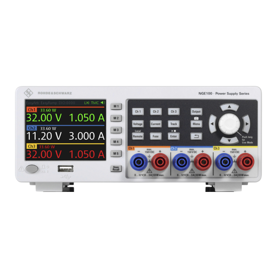
www.allice.de Allice Messtechnik GmbH ® Welcome to R&S NGE100B R&S NGE100B 2 Welcome to R&S NGE100B The two or three-channels power supply series are based on a classical transformer concept with high efficiency electronic pre-regulators and secondary linear regulators. This concept allows the instrument to achieve the high output power within a minimum space, high efficiency and lowest residual ripple. -
Page 12: Important Notes
www.allice.de Allice Messtechnik GmbH ® Important Notes R&S NGE100B Ambient Conditions 3 Important Notes 3.1 Symbols Caution, general danger zone Ground PE terminal ON (supply voltage) OFF (supply voltage) Ground terminal 3.2 Ambient Conditions The allowed operating temperature ranges from +0 °C to +40 °C (pollution category 2). The maximum relative humidity (without condensation) is at 80 %. -
Page 13: Measurement Categories
www.allice.de Allice Messtechnik GmbH ® Important Notes R&S NGE100B Mains Voltage ~72 °C, a channel-specific overheat protection intervenes. Affected outputs will auto- matically be switched off. Air circulation Do not obstruct the ventilation holes! 3.3 Measurement Categories This instrument is designed for supplying power on circuits that are only indirectly con- nected to the low voltage mains or not connected at all. -
Page 14: Limits
www.allice.de Allice Messtechnik GmbH ® Important Notes R&S NGE100B Limits circuiting the fuse holder is prohibited. Resulting damages are not covered by the war- ranty. Safe operation If the instrument is to remain unattended for a longer time period, it must be switched off at the mains switch for safety reasons. -
Page 15: Quick Start
www.allice.de Allice Messtechnik GmbH ® Quick Start R&S NGE100B Putting into Operation 4 Quick Start The following chapters under Quick Start are identical to the printed R&S NGE100B Quick Start manual. ● Putting into Operation..................... 13 ● Instrument Tour....................... 19 ●... -
Page 16: Safety
www.allice.de Allice Messtechnik GmbH ® Quick Start R&S NGE100B Putting into Operation Risk of instrument damage during operation An unsuitable operating site or test setup can cause damage to the instrument and the connected devices. Ensure the following operating conditions before you switch on the instrument: ●... -
Page 17: Intended Operation
www.allice.de Allice Messtechnik GmbH ® Quick Start R&S NGE100B Putting into Operation Risk of electric shock It is prohibited to disconnect the earthed protective connection inside or outside of the instrument! If it is assumed that a safe operation is no longer possible, the instrument must be shut down and secured against any unintended operation. - Page 18 www.allice.de Allice Messtechnik GmbH ® Quick Start R&S NGE100B Putting into Operation Use only the power cord included in the delivery package. See "Delivery package" on page 17. Before each measurement, measuring cables must be inspected for damage and replaced if necessary. Damaged or worn components can damage the instrument or cause injury.
-
Page 19: Unpacking And Checking The Instrument
www.allice.de Allice Messtechnik GmbH ® Quick Start R&S NGE100B Putting into Operation 4.1.3 Unpacking and Checking the Instrument Check the equipment for completeness using the delivery note and package contents list for the various items. Check the instrument for any damage and loose parts. If there is any damage, immediately contact the carrier who delivered the instrument. -
Page 20: Bench Operation
www.allice.de Allice Messtechnik GmbH ® Quick Start R&S NGE100B Putting into Operation 4.1.4.1 Bench Operation On a benchtop, the R&S NGE100B can either lie flat or stand on its feet. As shown in Figure 4-1, feet on the bottom can be folded out to set the instrument in an inclined position. -
Page 21: Instrument Tour
www.allice.de Allice Messtechnik GmbH ® Quick Start R&S NGE100B Instrument Tour 4.2 Instrument Tour This chapter provides an overview of all the controls available in the R&S NGE100B models and steps to switch on the instrument for the first time. ●... -
Page 22: Rear Panel
www.allice.de Allice Messtechnik GmbH ® Quick Start R&S NGE100B Instrument Tour For a detailed description on-screen layout, see section "Screen Layout" in the User Manual. Function keys Function keys are means of input for manual operation of the instrument functions. When a function key is pressed, all the related keys are also illuminated. - Page 23 This connector is used for establishing remote control via SCPI or LXI. See section "Ethernet Setup" in the user manual for more information on the connection setup. The Ethernet option NGE-K101 must be installed for this function to be available in the instrument.
-
Page 24: Switching On The Instrument
www.allice.de Allice Messtechnik GmbH ® Quick Start R&S NGE100B Instrument Tour Digital I/O connector The Digital I/O connector is a terminal block for external trigger input or output. Measurement control can be achieved by means of an external input signal or using an external output signal to trigger other instruments for some measurements. -
Page 25: Trying Out The Instrument
www.allice.de Allice Messtechnik GmbH ® Quick Start R&S NGE100B Trying Out the Instrument 4.3 Trying Out the Instrument This chapter describes some basic functions that you can perform with the R&S NGE100B. 4.3.1 Selecting the Channels To select a channel, press the corresponding channel key. The key illuminates. 4.3.2 Setting the Output Voltage and Current Limit To set the output voltage and current limit via Live-Mode: 1. -
Page 26: Maintenance
www.allice.de Allice Messtechnik GmbH ® Quick Start R&S NGE100B Maintenance To retrieve the desired saved settings, press Store Recall key and select the memory location key (M1 to M5). 4.4 Maintenance Before cleaning the instrument, ensure that it has been switched off and power cable is disconnected. -
Page 27: Instrument Functions
The "xxxx" refers to I/O status for DIO1, DIO2, DIO3, DIO4. Wireless LAN connection (WLAN option R&S NGE-K102 must be instal- led). Wired LAN connection with LXI service for remote control operation (Ethernet option R&S NGE-K101 must be installed). User Manual 5601.1343.02 ─ 02... - Page 28 WLAN Disconnected or disabled or option NGE- Grey K102 uninstalled Connecting to access point Yellow Connected to access point Green LAN/LXI fault or option NGE-K101 uninstalled Red LAN/LXI in operation Green TMC connection selected Green VCP connection selected Green Speaker...
- Page 29 www.allice.de Allice Messtechnik GmbH ® Instrument Functions R&S NGE100B User Interface Figure 5-2: Channel display area for 3-channel and 2-channel instrument Table 5-3: Available parameters in the channel display area Parameter Description Channel Display channel number. Power Display output power in Watt. Voltage Voltage in Volt.
-
Page 30: Function Keys
www.allice.de Allice Messtechnik GmbH ® Instrument Functions R&S NGE100B User Interface Color Operating mode Description Inactive mode Display only. Editing mode A solid blue background is shown when an item is selected. CV mode Active outputs are operated in a constant voltage mode. -
Page 31: Virtual Keyboard
www.allice.de Allice Messtechnik GmbH ® Instrument Functions R&S NGE100B User Interface Function keys Description Voltage Sets the output voltage for the channel. See "Set output voltage and current" on page 35. Current Sets the output current limit for the channel. See "Set output voltage and current"... -
Page 32: Navigation Controls
www.allice.de Allice Messtechnik GmbH ® Instrument Functions R&S NGE100B User Interface Figure 5-4: Virtual keyboard Invoke the virtual keyboard as follows: 1. Move the cursor to the desired input field. 2. Press Enter key. The virtual keyboard appears. 3. Once on the keyboard screen, press the arrow keys or turn the rotary knob to go to the desired character. -
Page 33: Rotary Knob
www.allice.de Allice Messtechnik GmbH ® Instrument Functions R&S NGE100B User Interface Rotary Knob Arrow keys Live-mode 5.1.4.1 Rotary Knob Step size changes of the numeric value correspond to the speed of the rotary knob. The rotary knob has several functions depending on the mode it is in. ●... -
Page 34: Menu
www.allice.de Allice Messtechnik GmbH ® Instrument Functions R&S NGE100B User Interface 5.1.5 Menu The R&S NGE100B menu provides access to the instrument's advanced functions and some general settings. You can also obtain the instrument and service information via the menu. To access this mode: 1. - Page 35 Descriptions Interface Ethernet Configures the Ethernet interface. See Figure 5-20. The Ethernet option NGE-K101 must be installed for this function to be available in the instrument. WLAN Configures the WLAN interface. See Figure 5-21. The WLAN option NGE-K102 must be installed for this function to be available in the instrument.
-
Page 36: Power Derating
www.allice.de Allice Messtechnik GmbH ® Instrument Functions R&S NGE100B Output Modes 5.2 Power Derating The NGE103B includes three identical channels with a continuous voltage range of 0 to 32 V. The instrument provides a source of up to 3 A at 11.2 V and at 32 V, it provides up to 1.05 A using the sophisticated power management. -
Page 37: Basic Functions
www.allice.de Allice Messtechnik GmbH ® Instrument Functions R&S NGE100B Basic Functions Figure 5-8: Current limit CC mode The current I corresponds to the current setting adjustable in the instrument. If I reaches I , the instrument switches to CC mode, i.e. the output current remains constant and limited to I even if the load increases. -
Page 38: Tracking Function
www.allice.de Allice Messtechnik GmbH ® Instrument Functions R&S NGE100B Basic Functions The setting of current value corresponds to the I of the respective channel. It is advisable to set the current limit prior to operating the instrument to prevent damage to the load and instrument in the case of malfunction like short-circuit. -
Page 39: Activating Fuse
www.allice.de Allice Messtechnik GmbH ® Instrument Functions R&S NGE100B Basic Functions 3. Press Current key if current values should be tracked. The selected channels are highlighted in blue and all the navigation controls illumi- nate. Selected Voltage or Current key is also illuminated. 4. -
Page 40: Activating The Channels Output
www.allice.de Allice Messtechnik GmbH ® Instrument Functions R&S NGE100B Basic Functions A delay can be applied to every channel fuse. Also, individual electronic fuses (Fuse- Link) can be logically linked so as to switch off the interlinked channels. For more information, see Fuse for the fuse delay and FuseLink configuration. - Page 41 www.allice.de Allice Messtechnik GmbH ® Instrument Functions R&S NGE100B Basic Functions Auto save instrument settings Auto save of instrument settings are applied when any of the following parameters are changed: ● General instrument settings ● USB connection mode ● WLAN settings –...
-
Page 42: Advanced Functions
www.allice.de Allice Messtechnik GmbH ® Instrument Functions R&S NGE100B Advanced Functions 2. Press any of the memory keys (M1, M2, M3, M4, M5) to store the instrument set- tings. The R&S NGE100B stores the instruments settings in the selected memory loca- tion. - Page 43 www.allice.de Allice Messtechnik GmbH ® Instrument Functions R&S NGE100B Advanced Functions A beep is sounded if buzzer is enabled. See Figure 5-25. Figure 5-13: Indicator of OVP/OPP when tripped 1. Select "Output > Protection" menu item. The R&S NGE100B displays the "Protection" dialog. See Figure 5-14.
-
Page 44: Fuse
www.allice.de Allice Messtechnik GmbH ® Instrument Functions R&S NGE100B Advanced Functions 5. Set the desired voltage for OPP. You can set a value from 0 W to 33.6 W. The R&S NGE100B turns off the respective channel when the measured power exceeded the preset value. -
Page 45: Easyarb
www.allice.de Allice Messtechnik GmbH ® Instrument Functions R&S NGE100B Advanced Functions ● "Disabled": Ch 1 is not linked to any other channels. 5.5.3 EasyArb EasyArb function The arbitrary function is available only in Ch 1. The R&S NGE100B series allows you to generate freely programmable waveforms which can be reproduced within the limits set by the instrument for voltage and current. -
Page 46: Easyramp
www.allice.de Allice Messtechnik GmbH ® Instrument Functions R&S NGE100B Advanced Functions The Enter key is illuminated. 9. Press Output key to enable R&S NGE100B output. 10. Press Enter key to start the EasyArb function. 11. Long press on the Enter key to stop the EasyArb function. Table 5-9: EasyAab input field EasyArb input field Description... -
Page 47: Digital Trigger I/O
www.allice.de Allice Messtechnik GmbH ® Instrument Functions R&S NGE100B Advanced Functions 1. Select "Output > EasyRamp" menu item. The R&S NGE100B displays the "EasyRamp" dialog. See Figure 5-18. Figure 5-18: EasyRamp dialog 2. Select the desired channel. 3. Set the selected channel to "Enabled". The R&S NGE100B enabled the EasyRamp function for the selected channel. - Page 48 www.allice.de Allice Messtechnik GmbH ® Instrument Functions R&S NGE100B Advanced Functions The four data lines of the digital I/O interface are mutually independent and can be used as trigger input or trigger output separately. See Figure 4-4. ● Trigger input The data lines of the digital I/O interface receive external trigger signal.
- Page 49 www.allice.de Allice Messtechnik GmbH ® Instrument Functions R&S NGE100B Advanced Functions Trigger out parameters Trigger conditions Description Output Off Output the selected logic level when the Output is turned off at the selected channel. Fuse Tripped Output the selected logic level when a fuse tripped event occurs on the selected chan- nel.
-
Page 50: Connecting To A Network
5.6 Connecting to a Network 5.6.1 LAN Connection R&S NGE-K101 (order number: 5601.2204.03) option is required to connect the R&S NGE100B to a network via LAN connection. There are two methods to establish a local area network (LAN) connection with the R&S NGE100B for remote control operation. - Page 51 www.allice.de Allice Messtechnik GmbH ® Instrument Functions R&S NGE100B Connecting to a Network Depending on the network capacities, the TCP/IP address information for the instru- ment can be obtained in different ways. ● If the network supports dynamic TCP/IP configuration using the Dynamic Host Configuration Protocol (DHCP), and a DHCP server is available, all address infor- mation can be assigned automatically.
-
Page 52: Wireless Connection
www.allice.de Allice Messtechnik GmbH ® Instrument Functions R&S NGE100B Connecting to a Network When the connection is alive, the LXI icon turns green on the status bar. Table 5-13: Ethernet input field Ethernet input field Description MAC Address Shows the MAC address of this instrument. Status Shows if the connection is up or down. -
Page 53: Usb Connection
www.allice.de Allice Messtechnik GmbH ® Instrument Functions R&S NGE100B Connecting to a Network Figure 5-21: WLAN dialog 2. Select "Enabled" for "Module". 3. Set the "SSID" SSID - Service Set Identifier, an unique ID used for naming wireless network. 4. Set the associated password for the "SSID". 5. -
Page 54: General Instrument Settings
www.allice.de Allice Messtechnik GmbH ® Instrument Functions R&S NGE100B General Instrument Settings Figure 5-23: USB dialog 2. Set the desired "USB Mode". 3. Press Enter key to confirm the settings. The R&S NGE100B displays message to prompt the user to restart the instrument to apply the changes. -
Page 55: General Instrument Settings
www.allice.de Allice Messtechnik GmbH ® Instrument Functions R&S NGE100B General Instrument Settings Device information Description Device Model Model of the instrument, i.e. NGE102B or NGE103B. Serial Number Unique identification number for the instrument. Material Number Instrument orderable part number. Firmware Version Software version that is installed in the instrument. -
Page 56: Managing Options
www.allice.de Allice Messtechnik GmbH ® Instrument Functions R&S NGE100B General Instrument Settings General instrument settings Description Keypad Selects the wait time before the instrument automat- ically leaves the editing mode. Select "Off" to dis- able the automatic switching back. Display Selects the specific screen intensity to control the screen brightness. -
Page 57: Reset Instrument
www.allice.de Allice Messtechnik GmbH ® Instrument Functions R&S NGE100B General Instrument Settings 3. Select "Install". If the correct key code is entered, the option is marked as "Installed". If an invalid key code is entered, an error message is displayed. Re-enter the cor- rect key code. -
Page 58: Updating The Firmware
www.allice.de Allice Messtechnik GmbH ® Instrument Functions R&S NGE100B General Instrument Settings System Test Description Screen Test Test that the display is working. RGB and a list of supported colors should appear on the screen dur- ing the test. Key Backlight Test Test that the key backlight is working. -
Page 59: Help
www.allice.de Allice Messtechnik GmbH ® Instrument Functions R&S NGE100B General Instrument Settings Figure 5-29: Update dialog 6. Press Enter key to start firmware update process. The R&S NGE100B reboots automatically as part of the update process. 7. Press Enter key to confirm the update when prompt. 8. - Page 60 www.allice.de Allice Messtechnik GmbH ® Instrument Functions R&S NGE100B General Instrument Settings Figure 5-30: Help dialog 2. Use a QR code reader to scan the QR code to link to the online product home page. Alternatively, you could enter the address: http://www.rohde-schwarz.com/product/ nge100b into a browser to access the latest help information.
-
Page 61: Remote Control
This chapter provides information on operating an instrument via remote control. 6.1 Interfaces and Protocols R&S NGE100B can be remotely controlled via the following interfaces: ● ● Available only if option R&S NGE-K101 is installed. ● WLAN Available only if option R&S NGE-K102 is installed. 6.1.1 USB The R&S NGE100B includes a USB device port. -
Page 62: Usb Tmc
www.allice.de Allice Messtechnik GmbH ® Remote Control R&S NGE100B Interfaces and Protocols 6.1.1.2 USB TMC The USB Test & Measurement class (USB-TMC) is a protocol that allows GPIB-like communication via USB interfaces and is a separate instrument class of the USB spec- ification. -
Page 63: Lan
www.allice.de Allice Messtechnik GmbH ® Remote Control R&S NGE100B Interfaces and Protocols Figure 6-1: Device manager 6.1.2 LAN For direct connection to a host (PC) or indirect connection via a switch, a double shiel- ded network cable (e.g. CAT.5, CAT.5e, CAT.5 +, CAT.6 or CAT.7) is required and equipped with an Ethernet plug type (RJ-45 type connector) on both sides. -
Page 64: Lxi
www.allice.de Allice Messtechnik GmbH ® Remote Control R&S NGE100B Interfaces and Protocols Equipped with option R&S NGE-K102, the R&S NGE100B provides an alternative to remote control the instrument via the web. With the presence of an authenticated WLAN signal, the instrument automatically connects to a network and navigation can be made via the web browser according to the WLAN IEEE 802.11 b/g/n standards. -
Page 65: Scpi
www.allice.de Allice Messtechnik GmbH ® Remote Control R&S NGE100B Interfaces and Protocols A key component of an LXI certification is the IVI device driver (Interchangeable Virtual Instrument). Here IVI.NET drivers are provided, which are based on the .NET frame- work 4 of Microsoft. LabView and LabWindows/CVI drivers built on LabWindows/CVI 2012 are also available. -
Page 66: Visa
www.allice.de Allice Messtechnik GmbH ® Remote Control R&S NGE100B Setting Up Remote Control Connection 6.1.6 VISA VISA is a standardized software interface library providing input and output functions to communicate with instruments. The I/O channel (LAN or USB) is selected at initializa- tion time by means of a channel-specific resource string. -
Page 67: Scpi Command Structure And Syntax
www.allice.de Allice Messtechnik GmbH ® Remote Control R&S NGE100B SCPI Command Structure and Syntax Remote Press Remote to unlock the instrument from the remote control mode. In thithe remotes mode, all front panel keys on the instrument are disable and the Remote is illuminated. -
Page 68: Device-Specific Commands
www.allice.de Allice Messtechnik GmbH ® Remote Control R&S NGE100B SCPI Command Structure and Syntax Table 6-1: List of supported common commands Mnemonic Name & 488.2 Section *IDN? Identification Query 10.14 *OPC Operation Complete Command 10.18 *OPC? Operation Complete Query 10.19 *RST Reset Command 10.32 *TST? - Page 69 www.allice.de Allice Messtechnik GmbH ® Remote Control R&S NGE100B SCPI Command Structure and Syntax Figure 6-3: Tree structure the SCPI command systems using the SOURce system as example Multiple keywords Some key words occur in several levels within one command system. Their effect depends on the structure of the command, i.e.
- Page 70 www.allice.de Allice Messtechnik GmbH ® Remote Control R&S NGE100B SCPI Command Structure and Syntax Optional keywords with numeric suffixes Do not omit an optional keyword if it includes a numeric suffix that is relevant for the effect of the command. Long and Short Form The key words feature a long form and a short form.
-
Page 71: Overview Of Syntax Elements
www.allice.de Allice Messtechnik GmbH ® Remote Control R&S NGE100B SCPI Command Structure and Syntax ● Braces { } Parameters in curly brackets are optional and can be inserted once or several times, or omitted. Example – APPly {<voltage> | MIN | MAX} [, {<current> | MIN | MAX}] The following are valid commands: APPly APPly 6... -
Page 72: Parameters
www.allice.de Allice Messtechnik GmbH ® Remote Control R&S NGE100B SCPI Command Structure and Syntax Syntax Element Description The hash symbol # introduces binary, octal, hexa- decimal and block data. ● Binary: #B10110 ● Octal: #O7612 ● Hex: #HF3A7 " " A "white space" (ASCII-Code 0 to 9, 11 to 32 deci- mal, e.g. -
Page 73: Boolean Parameters
www.allice.de Allice Messtechnik GmbH ® Remote Control R&S NGE100B SCPI Command Structure and Syntax ● INF/NINF INFinity, Negative INFinity (NINF) Negative INFinity (NINF) represent the numerical values -9.9E37 or 9.9E37, respectively. INF and NINF are only sent as device response. ●... -
Page 74: Block Data
www.allice.de Allice Messtechnik GmbH ® Remote Control R&S NGE100B SCPI Command Structure and Syntax 6.3.2.6 Block Data Block data are a transmission format which is suitable for the transmission of large amounts of data. A command using a block data parameter has the following structure: Example: HEADer:HEADer #45168xxxxxxxx ASCII character # introduces the data block. -
Page 75: Command Sequence And Command Synchronization
www.allice.de Allice Messtechnik GmbH ® Remote Control R&S NGE100B Remote Control - Commands POWer:PROTection? Response: 0 (for OFF) ● Text (character data) is returned in a short form. Example VOLTage:PROTection:MODE? Response: MEAS (for Measured) 6.4 Command Sequence and Command Synchronization What has been said above makes clear that all commands can potentially be carried out overlapping. -
Page 76: Common Commands
www.allice.de Allice Messtechnik GmbH ® Remote Control R&S NGE100B Remote Control - Commands 6.5.1 Common Commands The common commands are taken from the IEEE 488.2 (IEC 625-2) standard. A par- ticular command has the same effect on different devices. The headers of these com- mands consist of an asterisk "*"... - Page 77 www.allice.de Allice Messtechnik GmbH ® Remote Control R&S NGE100B Remote Control - Commands *IDN? Identification Returns the instrument identification. Return values: <ID> "Rohde&Schwarz,<device type>,<part number>/serial num- ber>,<firmware version>" Example: Rohde&Schwarz,NGE103B,5601.1414k03/100421,1.20 *OPC Operation complete Sets bit 0 in the event status register when all preceding commands have been execu- ted.
-
Page 78: System Commands
www.allice.de Allice Messtechnik GmbH ® Remote Control R&S NGE100B Remote Control - Commands Prevents servicing of the subsequent commands until all preceding commands have been executed and all signals have settled (see also command synchronization and *OPC). Usage: Event 6.5.2 System Commands The following commands perform the various system functions and configure the com- munication interface (LAN, WLAN) for the instrument. - Page 79 Event SYSTem:COMMunicate:SOCKet:DHCP[:STATe] <arg0> This command sets or queries LAN interface mode. ON: automatic IP address from DHCP server; OFF: manually set IP address. Available only if option R&S NGE-K101 is installed. Parameters: <arg0> SYSTem:COMMunicate:SOCKet:IPADdress? This command queries IP address of the LAN interface.
- Page 80 www.allice.de Allice Messtechnik GmbH ® Remote Control R&S NGE100B Remote Control - Commands SYSTem:COMMunicate:WLAN:DISConnect The instrument stops the connection to the predefined wireless access point. Available only if option R&S NGE-K102 is installed. Usage: Event SYSTem:COMMunicate:WLAN:IPADdress? This command queries the IP address of the device when the wireless interface works as a client.
-
Page 81: Firmware Update
www.allice.de Allice Messtechnik GmbH ® Remote Control R&S NGE100B Remote Control - Commands 6.5.3 Firmware Update DIAGnostic:SERVice:FWUP <arg0> Starts instrument firmware update remotely. For more information, see Chapter 5.7.6, "Updating the Firmware", on page 56. Parameters: <arg0> Example: DIAGnostic:SERVice:FWUP "NGE100FWRelease.tar.gz.enc" Usage: Setting only 6.5.4 HCOPY... -
Page 82: Output Setting
www.allice.de Allice Messtechnik GmbH ® Remote Control R&S NGE100B Remote Control - Commands Parameters: <arg0> {1 | 2 | 3} Example: INSTrument:NSELect 1 Selects the output channel as Ch 1. Note: Channel 3 is only valid for NGE103B. INSTrument:NSELect? -> 1 Return the numeric channel selection. - Page 83 www.allice.de Allice Messtechnik GmbH ® Remote Control R&S NGE100B Remote Control - Commands Example: INST OUT1 OUTP ON Ch 1 and output state will be activated; i.e. Ch 1 and Output key on the front panel will be illuminated. OUTP? -> 1 Return the output state.
- Page 84 www.allice.de Allice Messtechnik GmbH ® Remote Control R&S NGE100B Remote Control - Commands Example: OUTP:MODE? -> CV Output mode has changed to constant voltage mdoe. Usage: Query only OUTPut:SELect <arg0> This command activates or queries the instrument channel state of the previous selected channedl.
-
Page 85: Fuse Setting
www.allice.de Allice Messtechnik GmbH ® Remote Control R&S NGE100B Remote Control - Commands 6.5.7 Fuse Setting FUSE:DELay <Delay> This command defines and queries the fuse delay for the previous selected channel. Parameters: <Delay> {<Delay> | MIN | MAX} <delay> 0 ms to 10 s (adjustable in 10 ms steps e.g. FUSE:DEL 10 = 10 Set fuse delay to minimum. - Page 86 www.allice.de Allice Messtechnik GmbH ® Remote Control R&S NGE100B Remote Control - Commands Return values: <arg0> Fuse is tripped. Fuse is not tripped. Example: INST OUT1 FUSE:TRIP? -> 0 Fuse of Ch 1 has not tripped. Usage: Query only FUSE:UNLink <arg0> This command unlinks the channel fuses (fuse linking) for the previous selected chan- nel.
-
Page 87: Ovp Setting
www.allice.de Allice Messtechnik GmbH ® Remote Control R&S NGE100B Remote Control - Commands 6.5.8 OVP Setting [SOURce:]VOLTage:PROTection:MODE <arg0> This command defines or queries the OVP mode for the previous selected channel. Parameters: <arg0> MEASured | PROTected MEASured The OVP switches off if the measured value exceeds the thresh- old. -
Page 88: Opp Setting
www.allice.de Allice Messtechnik GmbH ® Remote Control R&S NGE100B Remote Control - Commands Example: INST OUT1 VOLT:PROT ON OVP of Ch 1 is activated. VOLT:PROT? -> 1 Return the OVP state of the selected channel. [SOURce:]VOLTage:PROTection:LEVel <Voltage> This command defines or queries the OVP value of the previous selected channel. Parameters: <Voltage>... - Page 89 www.allice.de Allice Messtechnik GmbH ® Remote Control R&S NGE100B Remote Control - Commands Parameters: <Power> {<Voltage> | MIN | MAX} <Voltage> Set the OPP value in the range of 0 W up to 32 W (adjustable in 100 mW steps) Set the OPP value to minimum.
-
Page 90: Measurement Commands
www.allice.de Allice Messtechnik GmbH ® Remote Control R&S NGE100B Remote Control - Commands [SOURce:]POWer:PROTection:CLEar This command resets the OPP state of the selected channel. If the OPP has tripped the red blinking OPP message on the display will be cleared for the selected channel. Usage: Event 6.5.10 Measurement Commands... -
Page 91: Voltage And Current Configuration Commands
www.allice.de Allice Messtechnik GmbH ® Remote Control R&S NGE100B Remote Control - Commands 6.5.11 Voltage and Current Configuration Commands APPLy <arg0> This command defines or queries the voltage and current value of the selected chan- nel. Parameters: <arg0> {<Voltage> | DEF | MIN | MAX} [, {<Current> | DEF | MIN | MAX}] <Voltage>... -
Page 92: Easyramp Commands
www.allice.de Allice Messtechnik GmbH ® Remote Control R&S NGE100B Remote Control - Commands Parameters: <Voltage> {<Voltage> | MINimum | MAXimum | DEFault} <Voltage> 0.0 V to 32.2 V (adjustable in 10 mV steps) MINimum 0.000E+00 MAXimum 32.200E+01 Default unit: V Example: VOLT 10 Set the voltage value to 10 V. -
Page 93: Arbitrary Commands
www.allice.de Allice Messtechnik GmbH ® Remote Control R&S NGE100B Remote Control - Commands [SOURce:]VOLTage:RAMP[:STATe] <arg0> This command defines/queries the EasyRamp state for the previous selected channel. Parameters: <arg0> {OFF | ON} EasyRamp function is activated. EasyRamp function is disabled. 6.5.13 Arbitrary Commands ARBitrary:CLEar This command clears the previous defined arbitrary waveform data for channel 1. - Page 94 www.allice.de Allice Messtechnik GmbH ® Remote Control R&S NGE100B Remote Control - Commands ARBitrary:REPetitions <Repetitions> This command defines or queries the repetition of the defined arbitrary waveform for channel 1. Note: If the repetition is set to "0", the arbitrary waveform repeats continuously. Parameters: <Repetitions>...
-
Page 95: Dio Commands
www.allice.de Allice Messtechnik GmbH ® Remote Control R&S NGE100B Remote Control - Commands ARBitrary:STOP This command stops the EasyArb waveform in channel 1 if EasyArb is running. Usage: Event 6.5.14 DIO Commands TRIGger:DIRection:DIO<IO> <arg0> This command sets or queries the specified Digital I/O line to function as Trigger Input or Trigger Output. - Page 96 www.allice.de Allice Messtechnik GmbH ® Remote Control R&S NGE100B Remote Control - Commands Parameters: <arg0> PULSe | LEVel PULSe Starts EasyArb when trigger signal activated. LEVel Starts EasyArb when trigger signal activated and stops when trigger signal de-activated. *RST: PULSe Example: TRIG:IN:ARB:DIO1 PULS TRIGger:IN:RESPonse:DIO<IO>...
- Page 97 www.allice.de Allice Messtechnik GmbH ® Remote Control R&S NGE100B Remote Control - Commands Parameters: <arg0> CH1 | CH2 | CH3 Trigger input source from Ch 1. Trigger input source from Ch 2. Trigger input source from Ch 3. *RST: TRIGger:LOGic:DIO<IO> <arg0> This command sets or queries the trigger logic (Active High/Active Low) of the speci- fied Digital I/O line..
- Page 98 www.allice.de Allice Messtechnik GmbH ® Remote Control R&S NGE100B Remote Control - Commands Parameters: <arg0> ON | OFF | FUSetrip | CCMode | VOLTlevel | CURRlevel | CRITevent | ARBitrary Trigger output is turned on. Trigger output is turned off. FUSetrip Trigger output is linked to fuse tripped event.
- Page 99 www.allice.de Allice Messtechnik GmbH ® Remote Control R&S NGE100B Remote Control - Commands Parameters: <Current> *RST: 3.000 Default unit: A TRIGger:OUT:SOURce:DIO<IO> <arg0> This command sets or queries the control source of the trigger output of the specified Digital I/O line. Suffix: <IO>...
-
Page 100: Applications
www.allice.de Allice Messtechnik GmbH ® Applications R&S NGE100B Parallel and Serial Mode 7 Applications 7.1 Parallel and Serial Mode It is assumed that only qualified and trained personnel service the power supplies and the connected loads. Use only the R&S NGE100B power supply series when operating the channels in a serial or parallel mode to increase the output voltage and current. -
Page 101: Parallel Mode
www.allice.de Allice Messtechnik GmbH ® Applications R&S NGE100B Parallel and Serial Mode Figure 7-1: Example of serial connection 7.1.2 Parallel Mode If it is necessary to increase the total current, the power supply outputs must be wired in parallel. The maximum total current is the sum of the individual currents of all sour- ces connected in parallel. - Page 102 www.allice.de Allice Messtechnik GmbH ® Applications R&S NGE100B Parallel and Serial Mode Principles of operation in parallel mode Generally, a higher current will first be supplied from the channel with the higher output voltage. Once this channel reaches its power limit, the remaining current will be made available by the channel that is connected in parallel.
-
Page 103: Index
www.allice.de Allice Messtechnik GmbH ® Index R&S NGE100B Index Key Fallback Time ............53 Keypad ................ 53 Activating Fuse ..............37 Sound ................. 53 Activating the Channels Output ......... 38 Getting Started ..............7 Application cards ..............8 Application notes ..............8 Help ................... - Page 104 www.allice.de Allice Messtechnik GmbH ® Index R&S NGE100B Remote Control ..............59 Reset ................. 55 Reset values Remote ............... 75 Safety instructions ............... 7 SCPI Command Structure and Syntax ......65 Screen Layout ..............25 Selecting the Channels ............. 35 Service manual ..............
- Page 105 www.allice.de Allice Messtechnik GmbH AlliCE Messtechnik GmbH make ALLICE your partner ALLICE Messtechnik GmbH Kelsterbacher Strasse 15-19 60528 Frankfurt am Main Tel.: +49(0)69-67724-583 Fax: +49(0)69-67724-582 info@allice.de www.allice.de © 2018 Allice Messtechnik GmbH – Alle Rechte vorbehalten. © 2018 Allice Messtechnik GmbH – All rights reserved Verwendete Warenzeichen und Schutzrechte sind Eigentum der jeweiligen Hersteller.
Need help?
Do you have a question about the NGE-K101 and is the answer not in the manual?
Questions and answers