R&S NGE102B Getting Started
Hide thumbs
Also See for NGE102B:
- User manual (105 pages) ,
- User manual (117 pages) ,
- User manual (105 pages)
Table of Contents
Advertisement
Quick Links
Advertisement
Table of Contents

Related Manuals for R&S NGE102B


Summary of Contents for R&S NGE102B
- Page 1 ® R&S NGE100B Power Supply Getting Started (Æ1=U2) 5601133702 Version 08...
- Page 2 ® This manual describes the following R&S NGE100B models and options: ● R&S ® NGE102B 2-Channel PSU (5601.3800.02) ● R&S ® NGE103B 3-Channel PSU (5601.3800.03) The contents of this manual correspond to firmware version 1.50 or higher. © 2022 Rohde & Schwarz GmbH & Co. KG Muehldorfstr.
-
Page 3: Table Of Contents
® Contents R&S NGE100B Contents 1 Safety information..............5 2 Korea certification class A............6 3 Documentation overview............7 3.1 Manuals....................7 3.2 Data sheet....................7 3.3 Calibration certificate................8 3.4 Release notes, open source acknowledgment........8 4 Welcome to R&S NGE100B...........9 5 Putting into operation............10 5.1 Safety.................... - Page 4 ® Contents R&S NGE100B 7.3 Activating the channels output............25 7.4 Storing/Recalling of instrument settings..........25 8 Maintenance and support........... 26 8.1 Maintenance..................26 8.2 Contacting customer support............26 Index..................28 Getting Started 5601.1337.02 ─ 08...
-
Page 5: Safety Information
® Safety information R&S NGE100B Safety information The product documentation helps you use the R&S NGE100B safely and effi- ciently. Follow the instructions provided here and in the printed "Basic Safety Instructions". Keep the product documentation nearby and offer it to other users. Intended use The R&S NGE100B is intended for the development, production and verification of electronic components and devices in industrial, administrative, and laboratory... -
Page 6: Korea Certification Class A
® Korea certification class A R&S NGE100B Korea certification class A 이 기기는 업무용(A급) 전자파 적합기기로서 판매자 또는 사용자는 이 점을 주의하 시기 바라며, 가정외의 지역에서 사용하는 것을 목적으로 합니다. Getting Started 5601.1337.02 ─ 08... -
Page 7: Documentation Overview
® Documentation overview R&S NGE100B Data sheet Documentation overview This section provides an overview of the R&S NGE100B user documentation. Manuals You find the documents on the R&S NGE100B product page at: www.rohde-schwarz.com/product/nge100b Getting started Introduces the R&S NGE100B power supply series and describes how to set up and start working with the instrument. -
Page 8: Calibration Certificate
® Documentation overview R&S NGE100B Release notes, open source acknowledgment Calibration certificate The document is available on https://gloris.rohde-schwarz.com/calcert. You need the device ID of your instrument, which you can find on a label on the rear panel. Release notes, open source acknowledgment The release notes list new features, improvements and known issues of the cur- rent firmware version, and describe the firmware installation. -
Page 9: Welcome To R&S Nge100B
® Welcome to R&S NGE100B R&S NGE100B Welcome to R&S NGE100B The two or three-channel power supply series are based on a classical trans- former concept with high efficiency electronic pre-regulators and secondary linear regulators. This concept allows the instrument to achieve the high output power within a minimum space, high efficiency and lowest residual ripple. -
Page 10: Putting Into Operation
® Putting into operation R&S NGE100B Putting into operation This chapter describes the steps to set up the R&S NGE100B for the first time. Risk of injury and instrument damage The instrument must be used in an appropriate manner to prevent electric shock, fire, personal injury, or damage. -
Page 11: Safety
® Putting into operation R&S NGE100B Safety Risk of radio interference This is a class A product. In a domestic environment, this product may cause radio interference in which case the user may be required to take adequate measures. EMI impact on measurement results Electromagnetic interference (EMI) may affect the measurement results. - Page 12 ® Putting into operation R&S NGE100B Safety ment. It has been tested and shipped from the plant in safe condition. It is also in compliance with the regulations of the European standard EN 61010-1 and the international standard IEC 61010-1. To maintain this condition and ensure safe operation, you must observe all instructions and warnings given in this user manual.
-
Page 13: Intended Operation
® Putting into operation R&S NGE100B Intended operation Exceeding the low voltage protection Use insulated wires and not bare wires for the terminal connection. For the series connection of all output voltages, it is possible to exceed the low voltage protection of 42 V. Please note that in this case any contact with live components is life-threatening. - Page 14 Dimensions W x H x D 222 mm x 88 mm x 280 mm (8.74 in x 3.46 in x 11.02 in) Weight R&S NGE102B 4.9 kg (10.80 lb) R&S NGE103B 5.0 kg (11.02 lb) Getting Started 5601.1337.02 ─ 08...
-
Page 15: Unpacking And Checking The Instrument
® Putting into operation R&S NGE100B Unpacking and checking the instrument Unpacking and checking the instrument Check the equipment for completeness using the delivery note and package con- tents list for the various items. Check the instrument for any damage and loose parts. -
Page 16: Setting Up The Instrument
® Putting into operation R&S NGE100B Setting up the instrument ● One document folder containing Basic Safety instructions guide and CE certif- icate Setting up the instrument The R&S NGE100B is designed for benchtop and rackmount. 5.4.1 Bench operation On a benchtop, the R&S NGE100B can either lie flat or stand on its feet. As shown in Figure 5-1, feet on the bottom can be folded out to set the instrument in... -
Page 17: Rack Mounting
® Putting into operation R&S NGE100B Setting up the instrument Risk of injury if feet are folded out The feet can fold in if they are not folded out completely or if the instrument is shifted. Collapsing feet can cause injury or damage the instrument. ●... -
Page 18: Instrument Tour
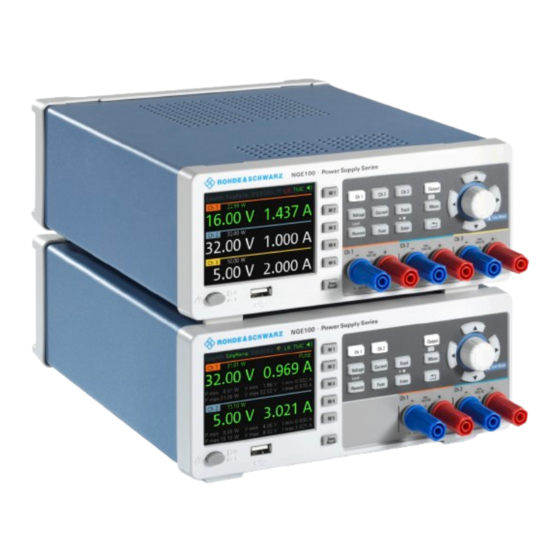
The following power supply models are available: Table 6-1: Power supply models Models Number of output channels R&S NGE102B (0 V - 32 V/3 A) 2 (maximum 66 W) R&S NGE103B (0 V - 32 V/3 A) 3 (maximum 100 W) Figure 6-1: Front panel of R&S NGE100B with 3 channels... - Page 19 ® Instrument tour R&S NGE100B Overview of controls 1 = Display 2 = Function keys 3 = Rotary knob and arrow keys 4 = Output channels (see Table 6-1) 5 = USB connector 6 = Power key Display (1) The display is a color LCD screen. Depending on the instrument models, up to three channels are shown on the screen.
-
Page 20: Rear Panel
® Instrument tour R&S NGE100B Overview of controls Power key (6) The [Power] key switches the instrument on and off. 6.1.2 Rear panel Figure 6-2 shows the rear panel of the R&S NGE100B with its connectors. Figure 6-2: Rear panel of R&S NGE100B 7 = Ground terminal 8 = AC inlet with fuse holder 9 = Voltage selector... - Page 21 ® Instrument tour R&S NGE100B Overview of controls AC inlet with fuse holder (8) Main supply cord Do not use detachable mains supply cord with inadequate rating. For safety reasons, the instrument can only be operated with authorized safety sockets. The power cable must be plugged in before signal circuits can be connected.
-
Page 22: Switching On The Instrument
® Instrument tour R&S NGE100B Switching on the instrument The voltage selector selects the mains voltage between 115 V and 230 V. See Table 5-1 for the fuse rating. Ethernet connector (10) This connector is used for establishing remote control via SCPI or LXI. See sec- tion "Ethernet Setup"... - Page 23 ® Instrument tour R&S NGE100B Switching on the instrument To change the power fuse / mains voltage setting: 1. Peel off the yellow label sticker on the AC inlet. 2. Pull out the fuse holder which is located directly on top of the socket. 3.
-
Page 24: Trying Out The Instrument
® Trying out the instrument R&S NGE100B Setting the output voltage and current limit Trying out the instrument This chapter describes some basic functions that you can perform with the R&S NGE100B. Selecting the channels To select a channel, press the corresponding channel key. The key illuminates. Setting the output voltage and current limit To set the output voltage and current limit via Live-Mode: 1. -
Page 25: Activating The Channels Output
® Trying out the instrument R&S NGE100B Storing/Recalling of instrument settings Activating the channels output The output voltages can be switched on or off regardless of the operating mode of the instrument. To activate the channel output, press the [Output] key on the front panel followed by the desired channel key or vice versa. -
Page 26: Maintenance And Support
® Maintenance and support R&S NGE100B Contacting customer support Maintenance and support Maintenance Regular maintenance improves the life span of the instrument, the following chap- ter provides information on instrument maintenance. Cleaning Before cleaning the instrument, ensure that it has been switched off and the power cable is disconnected. - Page 27 ® Maintenance and support R&S NGE100B Contacting customer support Contact information Contact our customer support center at www.rohde-schwarz.com/support, or fol- low this QR code: Figure 8-1: QR code to the Rohde & Schwarz support page Getting Started 5601.1337.02 ─ 08...
-
Page 28: Index
® Index R&S NGE100B Index Setting up the instrument Bench operation ........16 Calibration certificate ......... 8 Rack mounting ........16 Controls ........... 18 Switching off the instrument ....22 Customer support ........26 Switching on the instrument ....22 Data sheet ..........7 Trying out the instrument Documentation overview ......
Need help?
Do you have a question about the NGE102B and is the answer not in the manual?
Questions and answers