Juniper SRX110 Manual
Services gateway hardware
Hide thumbs
Also See for SRX110:
- Hardware manual (168 pages) ,
- Quick start manual (6 pages) ,
- Quick start manual (6 pages)

Related Manuals for Juniper SRX110


Summary of Contents for Juniper SRX110
- Page 1 SRX110 Services Gateway Hardware Published: 2012-03-01 Copyright © 2012, Juniper Networks, Inc.
- Page 2 Products made or sold by Juniper Networks or components thereof might be covered by one or more of the following patents that are owned by or licensed to Juniper Networks: U.S. Patent Nos. 5,473,599, 5,905,725, 5,909,440, 6,192,051, 6,333,650, 6,359,479, 6,406,312, 6,429,706, 6,459,579, 6,493,347, 6,538,518, 6,538,899, 6,552,918, 6,567,902, 6,578,186, and 6,590,785.
-
Page 3: Table Of Contents
SRX110 Services Gateway Description ........3... - Page 4 General Electrical Safety Guidelines and Warnings ....62 SRX110 Services Gateway Agency Approvals ......63 SRX110 Services Gateway Compliance Statements for EMC Requirements .
- Page 5 Unpacking the Services Gateway ........81 Unpacking the SRX110 Services Gateway ....... . 81 Verifying Parts Received with the SRX110 Services Gateway .
- Page 6 SRX110 Services Gateway Hardware Resetting the SRX110 Services Gateway ....... . 107 Chapter 15 Autoinstallation .
- Page 7 Returning the Services Gateway ........149 Return Procedure for the SRX110 Services Gateway ..... . . 149 Locating the SRX110 Services Gateway Component Serial Number and Agency Labels .
- Page 8 SRX110 Services Gateway Hardware viii Copyright © 2012, Juniper Networks, Inc.
- Page 9 SRX110H-VB) ........... 9 Figure 5: SRX110 Services Gateway Back Panel ......10 Figure 6: SRX110 Services Gateway Front Panel LEDs .
- Page 10 Figure 26: Connecting the SRX110 Services Gateway to the Power Supply ..102 Figure 27: Grounding the SRX110 Services Gateway ..... . . 103...
- Page 11 Introduction ............3 Table 3: SRX110 Services Gateway Models ....... . 4 Table 4: SRX110 Services Gateway Hardware Features .
- Page 12 Table 36: SRX Services Gateway Rack Installation Parts ....90 Table 37: SRX110 Services Gateway Wall Installation Parts ....96 Table 38: 3G USB Modem with USB Protection Cover Components .
- Page 13 Returning the Services Gateway ........149 Table 50: Return Procedure for SRX110 Services Gateway ....149 Copyright ©...
- Page 14 SRX110 Services Gateway Hardware Copyright © 2012, Juniper Networks, Inc.
-
Page 15: About The Documentation
® To obtain the most current version of all Juniper Networks technical documentation, see the product documentation page on the Juniper Networks website at http://www.juniper.net/techpubs/ If the information in the latest release notes differs from the information in the documentation, follow the product Release Notes. -
Page 16: Table 1: Notice Icons
The console port is labeled CONSOLE on routing platform components. < > (angle brackets) Enclose optional keywords or variables. < > stub default-metric metric Copyright © 2012, Juniper Networks, Inc. -
Page 17: Documentation Feedback
Software release version (if applicable) Requesting Technical Support Technical product support is available through the Juniper Networks Technical Assistance Center (JTAC). If you are a customer with an active J-Care or JNASC support contract, Copyright © 2012, Juniper Networks, Inc. -
Page 18: Self-Help Online Tools And Resources
7 days a week, 365 days a year. Self-Help Online Tools and Resources For quick and easy problem resolution, Juniper Networks has designed an online self-service portal called the Customer Support Center (CSC) that provides you with the following features: Find CSC offerings: http://www.juniper.net/customers/support/... -
Page 19: Overview
Overview Introduction on page 3 Hardware Components and Specifications on page 7 SRX110 Services Gateway 3G USB Modem on page 19 SRX110 Services Gateway Integrated VDSL2 Interface on page 25 Physical Interface Modules Documentation on page 31 Copyright © 2012, Juniper Networks, Inc. - Page 20 SRX110 Services Gateway Hardware Copyright © 2012, Juniper Networks, Inc.
-
Page 21: Introduction
The Juniper Networks SRX110 Services Gateway offers complete functionality and flexibility for delivering secure and reliable data along with multiple integrated interfaces that support WAN and LAN connectivity. The SRX110 Services Gateway supports interfaces such as 3G USB modem and integrated very-high-bit-rate digital subscriber line version 2 (VDSL2). -
Page 22: Srx110 Services Gateway Models
On a single line, you type commands that are executed when you press the Enter key. The CLI provides command Help and command completion. For more details on the SRX110 Services Gateway software features and licenses, see the following guides:... -
Page 23: Srx110 Services Gateway Hardware Features
For this, you need to contact Juniper Networks Technical Assistance Center (JTAC). For more details on Junos OS features and licenses for the SRX110 Services Gateway, see the following guides: Junos OS Initial Configuration Guide for Security Devices... - Page 24 SRX110 Services Gateway Hardware Junos OS Monitoring and Troubleshooting Guide for Security Devices Related SRX110 Services Gateway Description on page 3 Documentation SRX110 Services Gateway Specifications on page 7 Copyright © 2012, Juniper Networks, Inc.
-
Page 25: Hardware Components And Specifications
SRX110 Services Gateway Power Supply on page 17 SRX110 Services Gateway Specifications The SRX110 Services Gateway chassis is a rigid sheet metal structure of 1 rack unit (U) height, which houses all the other hardware components. Figure 1 on page 7 shows the SRX110 Services Gateway with 3G and VDSL2 (VDSL/ADSL-POTS). -
Page 26: Figure 2: Srx110 Services Gateway With 3G And Vdsl2 (Vdsl/Adsl-Isdn)
SRX110 Services Gateway Hardware Figure 2: SRX110 Services Gateway with 3G and VDSL2 (VDSL/ADSL-ISDN) NOTE: SRX110B-VA and SRX110B-VB do not support security features such as unified threat management and intrusion detection and prevention. Table 5 on page 8 provides information on the physical specifications of the SRX110 Services Gateway. -
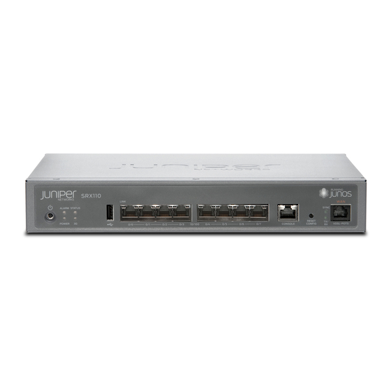
Page 27: Srx110 Services Gateway Front Panel And Back Panel Views With 3G And Integrated Vdsl2
VDSL2 This topic includes the following sections: SRX110 Services Gateway Front Panel View with 3G and Integrated VDSL2 on page 9 SRX110 Services Gateway Back Panel View on page 10 SRX110 Services Gateway Front Panel View with 3G and Integrated VDSL2... -
Page 28: Srx110 Services Gateway Back Panel View
For more information on the front panel components, see the following topics: SRX110 Services Gateway Built-In Interfaces on page 11 SRX110 Services Gateway LEDs on page 13 SRX110 Services Gateway Boot Devices and Dual-Root Partitioning Scheme on page 16 SRX110 Services Gateway Back Panel View Figure 5 on page 10 shows the back panel of the SRX110 Services Gateway. -
Page 29: Srx110 Services Gateway Built-In Interfaces
Chapter 2: Hardware Components and Specifications Table 7: SRX110 Services Gateway Back Panel Components (continued) Number Component Lock Grounding point CompactFlash card Power supply unit Cable tie holder NOTE: If there is any problem with the CompactFlash card, you must return the services gateway for repair or replacement. -
Page 30: Table 8: Srx110 Services Gateway Built-In Hardware Interfaces
SRX110 Services Gateway Hardware Table 8: SRX110 Services Gateway Built-In Hardware Interfaces Interface Specification Description Fast Ethernet The Fast Ethernet ports: The Fast Ethernet ports can be used: Consist of eight fixed ports To provide LAN connectivity Are labeled as port 0/0 to... -
Page 31: Srx110 Services Gateway Leds
3G USB modem. Related SRX110 Services Gateway Specifications on page 7 Documentation SRX110 Services Gateway Front Panel and Back Panel Views with 3G and Integrated VDSL2 on page 9 SRX110 Services Gateway LEDs on page 13 SRX110 Services Gateway LEDs... -
Page 32: Table 9: Srx110 Services Gateway Front Panel Components Leds
SRX110 Services Gateway Hardware Table 9: SRX110 Services Gateway Front Panel Components LEDs Component Description Usage Alarm LED The Alarm LED has the following indicator colors: The Alarm LED can be used to gather information on Red and steadily on indicates a critical alarm. -
Page 33: Srx110 Services Gateway Ethernet Port Leds
Figure 7 on page 15 shows the device Ethernet port LEDs. Figure 7: SRX110 Services Gateway Ethernet Port LEDs Table 10 on page 15 describes the built-in Ethernet port LEDs. Table 10: SRX110 Services Gateway Built-In Ethernet Port LEDs Number Function Color State Description... -
Page 34: Srx110 Services Gateway Boot Devices And Dual-Root Partitioning Scheme
Junos OS image in the other root partition and remain fully functional. When the SRX110 Services Gateway powers up, it tries to boot Junos OS from the default storage medium. If the device fails to boot from the default storage medium, it tries to boot from the alternate storage medium. -
Page 35: Srx110 Services Gateway Power Supply
SRX110 Services Gateway Specifications on page 7 SRX110 Services Gateway Power Supply The power supply for the SRX110 Services Gateway is external. You must use the power supply adapter provided by Juniper Networks to provide power to the services gateway. - Page 36 SRX110 Services Gateway Hardware Copyright © 2012, Juniper Networks, Inc.
-
Page 37: Srx110 Services Gateway 3G Usb Modem
SRX110 Services Gateway 3G USB Modem Key Features on page 21 SRX110 Services Gateway 3G-WAN USB Port Physical Specifications on page 22 Configuring the 3G USB Modem on the SRX110 Services Gateway on page 22 SRX110 Services Gateway 3G USB Modem Overview... -
Page 38: Using The Srx110 Services Gateway 3G Usb Modem
SRX110 Services Gateway Hardware Table 11: Wireless USB Modems Supported by the SRX110 Services Gateway (continued) Wireless USB Modem Release Supported Sierra Wireless AirCard 319U. Not available from Junos OS Release 11.2 R3 and later. Juniper Networks. Using the SRX110 Services Gateway 3G USB Modem... -
Page 39: Srx110 Services Gateway 3G Usb Modem Key Features
Documentation VDSL2 on page 9 Installing a 3G USB Modem in the SRX110 Services Gateway USB Port on page 97 SRX110 Services Gateway 3G-WAN USB Port Physical Specifications on page 22 Configuring the 3G USB Modem on the SRX110 Services Gateway on page 22... -
Page 40: Srx110 Services Gateway 3G-Wan Usb Port Physical Specifications
SRX110 Services Gateway 3G USB Modem Overview on page 19 Documentation Installing a 3G USB Modem in the SRX110 Services Gateway USB Port on page 97 SRX110 Services Gateway 3G-WAN USB Port Physical Specifications on page 22 SRX110 Services Gateway 3G-WAN USB Port Physical Specifications... -
Page 41: Table 14: Srx110 Services Gateway 3G Usb Modem Basic Cli Commands
SRX110 Services Gateway 3G USB Modem Overview on page 19 Documentation Installing a 3G USB Modem in the SRX110 Services Gateway USB Port on page 97 SRX110 Services Gateway 3G-WAN USB Port Physical Specifications on page 22 Copyright © 2012, Juniper Networks, Inc. - Page 42 SRX110 Services Gateway Hardware Copyright © 2012, Juniper Networks, Inc.
-
Page 43: Srx110 Services Gateway Integrated Vdsl2 Interface
SRX110 Services Gateway Integrated VDSL2 Interface Supported Profiles on page 26 SRX110 Services Gateway Integrated VDSL2 Interface LEDs on page 27 Configuring the Integrated VDSL2 Interface on the SRX110 Services Gateway on page 28 SRX110 Services Gateway Integrated VDSL2 Interface Overview Very-high-bit-rate digital subscriber line (VDSL) technology is part of the xDSL family of modem technologies. -
Page 44: Srx110 Services Gateway Integrated Vdsl2 Interface Key Features
SRX110 Services Gateway Hardware Configuring the Integrated VDSL2 Interface on the SRX110 Services Gateway on page 28 SRX110 Services Gateway Integrated VDSL2 Interface Key Features The following features are supported on integrated VDSL2: ADSL/ADSL2/ADSL2+ backward compatibility with POTS supporting Annex-A (Annex-M) and ISDN supporting Annex-B Packet Mode Transfer (PTM) or Ethernet in the First Mile (EFM) (802.3ah) -
Page 45: Srx110 Services Gateway Integrated Vdsl2 Interface Leds
SRX110 Services Gateway Integrated VDSL2 Interface Overview on page 25 Documentation SRX110 Services Gateway Integrated VDSL2 Interface LEDs on page 27 Configuring the Integrated VDSL2 Interface on the SRX110 Services Gateway on page 28 SRX110 Services Gateway Integrated VDSL2 Interface LEDs The integrated VDSL2 interface has two LEDs. -
Page 46: Configuring The Integrated Vdsl2 Interface On The Srx110 Services Gateway
SRX110 Services Gateway Hardware Configuring the Integrated VDSL2 Interface on the SRX110 Services Gateway To use J-Web to perform basic configuration for the integrated VDSL2 interface and to configure network interfaces for the services gateway: In J-Web, select Configure>Interfaces. The Interfaces page appears and lists the network interfaces present on the services gateway, along with configuration information (if configured). - Page 47 Junos OS Interfaces Configuration Guide for Security Devices Related SRX110 Services Gateway Integrated VDSL2 Interface Overview on page 25 Documentation SRX110 Services Gateway Integrated VDSL2 Interface Key Features on page 26 SRX110 Services Gateway Integrated VDSL2 Interface LEDs on page 27 Copyright © 2012, Juniper Networks, Inc.
- Page 48 SRX110 Services Gateway Hardware Copyright © 2012, Juniper Networks, Inc.
-
Page 49: Physical Interface Modules Documentation
CHAPTER 5 Physical Interface Modules Documentation Copyright © 2012, Juniper Networks, Inc. - Page 50 SRX110 Services Gateway Hardware Copyright © 2012, Juniper Networks, Inc.
-
Page 51: Planning
Planning Preparing the Site for Installation on page 35 Safety and Regulatory Compliance Information on page 43 Power Guidelines, Requirements, and Specifications on page 67 Interface Cable Specifications and Connector Pinouts on page 71 Copyright © 2012, Juniper Networks, Inc. - Page 52 SRX110 Services Gateway Hardware Copyright © 2012, Juniper Networks, Inc.
-
Page 53: Preparing The Site For Installation
Preparing the Site for Installation Site Preparation Checklist for the SRX110 Services Gateway on page 35 General Site Guidelines for Installing the SRX110 Services Gateway on page 38 SRX110 Services Gateway Cabinet Requirements on page 38 SRX110 Services Gateway Rack Requirements on page 39... - Page 54 85 structure. Cabinet Requirements Verify that your “SRX110 cabinet meets the Services minimum Gateway requirements. Cabinet Requirements” Plan the cabinet on page 38 location, including the required space clearances. Wall Installation Copyright © 2012, Juniper Networks, Inc.
- Page 55 SRX110 Services Gateway Specifications on page 7 Documentation Installation Overview for the SRX110 Services Gateway on page 77 General Site Guidelines for Installing the SRX110 Services Gateway on page 38 SRX110 Services Gateway Cabinet Requirements on page 38 SRX110 Services Gateway Rack Requirements on page 39...
-
Page 56: General Site Guidelines For Installing The Srx110 Services Gateway
Related SRX110 Services Gateway Specifications on page 7 Documentation SRX110 Services Gateway General Safety Guidelines and Warnings on page 45 Site Preparation Checklist for the SRX110 Services Gateway on page 35 SRX110 Services Gateway Rack Requirements on page 39 SRX110 Services Gateway Cabinet Requirements on page 38... -
Page 57: Srx110 Services Gateway Rack Requirements
A cabinet larger than the minimum required size provides better airflow and reduces the chance of overheating. Related General Site Guidelines for Installing the SRX110 Services Gateway on page 38 Documentation Site Preparation Checklist for the SRX110 Services Gateway on page 35... -
Page 58: Clearance Requirements For Airflow And Hardware Maintenance Of The Srx110 Services Gateway
For maximum stability, also secure the rack to ceiling brackets. Related General Site Guidelines for Installing the SRX110 Services Gateway on page 38 Documentation Site Preparation Checklist for the SRX110 Services Gateway on page 35... -
Page 59: Srx110 Services Gateway Electrical And Power Requirements
Related SRX110 Services Gateway Description on page 3 Documentation General Site Guidelines for Installing the SRX110 Services Gateway on page 38 Site Preparation Checklist for the SRX110 Services Gateway on page 35 SRX110 Services Gateway Cabinet Requirements on page 38... - Page 60 SRX110 Services Gateway Hardware Copyright © 2012, Juniper Networks, Inc.
-
Page 61: Safety And Regulatory Compliance Information
SRX110 Services Gateway Fire Safety Requirements on page 49 SRX110 Services Gateway Installation Safety Guidelines and Warnings on page 50 SRX110 Services Gateway Laser and LED Safety Guidelines and Warnings on page 54 SRX110 Services Gateway Maintenance and Operational Safety Guidelines and... - Page 62 Aviso Este símbolo de aviso indica perigo. Encontra-se numa situação que lhe poderá causar danos físicos. Antes de começar a trabalhar com qualquer equipamento, familiarize-se com os perigos relacionados com circuitos eléctricos, e com quaisquer práticas comuns que possam prevenir possíveis acidentes. Copyright © 2012, Juniper Networks, Inc.
-
Page 63: Srx110 Services Gateway General Safety Guidelines And Warnings
SRX110 Services Gateway Fire Safety Requirements on page 49 SRX110 Services Gateway Installation Safety Guidelines and Warnings on page 50 SRX110 Services Gateway Laser and LED Safety Guidelines and Warnings on page 54 SRX110 Services Gateway Electrical Safety Guidelines and Warnings on page 62... - Page 64 A restricted access area is an area to which access can be gained only by service personnel through the use of a special tool, lock and key, or other means of security, and which is controlled by the authority responsible for the location. Copyright © 2012, Juniper Networks, Inc.
- Page 65 Varning! Denna enhet är avsedd för installation i områden med begränsat tillträde. Ett område med begränsat tillträde får endast tillträdas av Copyright © 2012, Juniper Networks, Inc.
-
Page 66: Figure 10: Placing A Component Into An Electrostatic Bag
If you are returning a component, place it into an electrostatic bag before packing it. See Figure 10 on page Figure 10: Placing a Component into an Electrostatic Bag Copyright © 2012, Juniper Networks, Inc. -
Page 67: Srx110 Services Gateway Fire Safety Requirements
To keep warranties effective, do not use a dry chemical fire extinguisher to control a fire at or near a Juniper Networks services gateway. If a dry chemical fire extinguisher is used, the unit is no longer eligible for coverage under a service agreement. -
Page 68: Srx110 Services Gateway Installation Safety Guidelines And Warnings
SRX110 Services Gateway Hardware SRX110 Services Gateway Installation Safety Guidelines and Warnings Installation Instructions Warning WARNING: Read the installation instructions before you connect the services gateway to a power source. Waarschuwing Raadpleeg de installatie-aanwijzingen voordat u het systeem met de voeding verbindt. - Page 69 Les directives ci-dessous sont destinées à assurer la protection du personnel: Le rack sur lequel est monté le Juniper Networks services gateway doit être fixé à la structure du bâtiment. Si cette unité constitue la seule unité montée en casier, elle doit être placée dans le bas.
- Page 70 Le seguenti direttive vengono fornite per garantire la sicurezza personale: Il Juniper Networks services gateway deve essere installato in un telaio, il quale deve essere fissato alla struttura dell'edificio. Questa unità deve venire montata sul fondo del supporto, se si tratta dell'unica unità...
- Page 71 Para garantizar su seguridad, proceda según las siguientes instrucciones: El Juniper Networks services gateway debe instalarse en un bastidor fijado a la estructura del edificio. Colocar el equipo en la parte inferior del bastidor, cuando sea la única unidad en el mismo.
-
Page 72: Srx110 Services Gateway Laser And Led Safety Guidelines And Warnings
SRX110 Services Gateway Fire Safety Requirements on page 49 Documentation SRX110 Services Gateway Laser and LED Safety Guidelines and Warnings on page 54 SRX110 Services Gateway Laser and LED Safety Guidelines and Warnings General Laser Safety Guidelines on page 54... -
Page 73: Class 1 Led Product Warning
Waarschuwing Niet in de straal staren of hem rechtstreeks bekijken met optische instrumenten. Varoitus Älä katso säteeseen äläkä tarkastele sitä suoraan optisen laitteen avulla. Attention Ne pas fixer le faisceau des yeux, ni l'observer directement à l'aide d'instruments optiques. Copyright © 2012, Juniper Networks, Inc. -
Page 74: Radiation From Open Port Apertures Warning
åpning når det ikke er tilkoblet en fiberkabel. Aviso Dada a possibilidade de emissão de radiação invisível através do orifício da via de acesso, quando esta não tiver nenhum cabo de fibra conectado, Copyright © 2012, Juniper Networks, Inc. -
Page 75: Srx110 Services Gateway Maintenance And Operational Safety Guidelines And Warnings
öppningar. Related SRX110 Services Gateway Installation Safety Guidelines and Warnings on page 50 Documentation SRX110 Services Gateway Maintenance and Operational Safety Guidelines and Warnings... -
Page 76: Jewelry Removal Warning
ôter tout bijou (anneaux, colliers et montres compris). Lorsqu'ils sont branchés à l'alimentation et reliés à la terre, les objets métalliques chauffent, ce qui peut provoquer des blessures graves ou souder l'objet métallique aux bornes. Copyright © 2012, Juniper Networks, Inc. -
Page 77: Lightning Activity Warning
Varoitus Älä työskentele järjestelmän parissa äläkä yhdistä tai irrota kaapeleita ukkosilmalla. Attention Ne pas travailler sur le système ni brancher ou débrancher les câbles pendant un orage. Copyright © 2012, Juniper Networks, Inc. -
Page 78: Operating Temperature Warning
C). To prevent airflow restriction, allow at least 6 in. (15.2 cm) of clearance around the ventilation openings. Waarschuwing Om te voorkomen dat welke services gateway van de Juniper Networks services gateway dan ook oververhit raakt, dient u deze niet te bedienen op een plaats waar de maximale aanbevolen ο... -
Page 79: Product Disposal Warning
15,2 cm à volta das aberturas de ventilação. ¡Atención! Para impedir que un encaminador de la serie Juniper Networks services gateway se recaliente, no lo haga funcionar en un área en la que se ο... -
Page 80: Srx110 Services Gateway Electrical Safety Guidelines And Warnings
Related SRX110 Services Gateway Electrical Safety Guidelines and Warnings on page 62 Documentation SRX110 Services Gateway Laser and LED Safety Guidelines and Warnings on page 54 SRX110 Services Gateway Electrical Safety Guidelines and Warnings This topic includes the following sections:... -
Page 81: Srx110 Services Gateway Agency Approvals
Related SRX110 Services Gateway Power Specifications and Requirements on page 68 Documentation SRX110 Services Gateway Maintenance and Operational Safety Guidelines and Warnings... -
Page 82: Srx110 Services Gateway Compliance Statements For Emc Requirements
EN-61000-3-2 (2006) +A2 (2009) Power Line Harmonics EN-61000-3-3 (2008) Power Line Voltage Fluctuations Related SRX110 Services Gateway Electrical Safety Guidelines and Warnings on page 62 Documentation SRX110 Services Gateway Compliance Statements for EMC Requirements on page 64 SRX110 Services Gateway Compliance Statements for Environmental Requirements... -
Page 83: European Community
Reorient or relocate the receiving antenna. Increase the separation between the equipment and receiver. Copyright © 2012, Juniper Networks, Inc. -
Page 84: Srx110 Services Gateway Compliance Statements For Environmental
The maximum emitted sound pressure level is 70 dB(A) or less per EN ISO 7779. Related SRX110 Services Gateway Compliance Statements for Environmental Requirements Documentation on page 66 SRX110 Services Gateway Compliance Statements for EMC Requirements on page 64 SRX110 Services Gateway Agency Approvals on page 63 Copyright © 2012, Juniper Networks, Inc. -
Page 85: Power Guidelines, Requirements, And Specifications
CHAPTER 8 Power Guidelines, Requirements, and Specifications SRX110 Services Gateway Site Electrical Wiring Guidelines on page 67 SRX110 Services Gateway Power Specifications and Requirements on page 68 SRX110 Services Gateway Grounding Specifications on page 69 SRX110 Services Gateway Site Electrical Wiring Guidelines... -
Page 86: Srx110 Services Gateway Power Specifications And Requirements
SRX110 Services Gateway Power Specifications and Requirements on page 68 SRX110 Services Gateway Power Specifications and Requirements The AC power system electrical specifications for the SRX110 Services Gateway are listed Table 22 on page Table 22: Power Supply Electrical Specifications for the SRX110 Services... -
Page 87: Srx110 Services Gateway Grounding Specifications
SRX110 Services Gateway Site Electrical Wiring Guidelines on page 67 Documentation SRX110 Services Gateway Power Specifications and Requirements on page 68 Interface Cable and Wire Specifications for the SRX110 Services Gateway on page 71 Grounding the SRX110 Services Gateway on page 103 Copyright © 2012, Juniper Networks, Inc. - Page 88 SRX110 Services Gateway Hardware Copyright © 2012, Juniper Networks, Inc.
-
Page 89: Interface Cable Specifications And Connector Pinouts
Interface Cable Specifications and Connector Pinouts Interface Cable and Wire Specifications for the SRX110 Services Gateway on page 71 RJ-45 Connector Pinouts for the SRX110 Services Gateway Ethernet Port on page 72 RJ-45 Connector Pinouts for the SRX110 Services Gateway Console Port on page 73... -
Page 90: Rj-45 Connector Pinouts For The Srx110 Services Gateway Ethernet Port
SRX110 Services Gateway Hardware SRX110 Services Gateway Front Panel and Back Panel Views with 3G and Integrated VDSL2 on page 9 RJ-45 Connector Pinouts for the SRX110 Services Gateway Ethernet Port Figure 11 on page 72 shows the RJ-45 cable connector pinouts for Ethernet ports. -
Page 91: Rj-45 Connector Pinouts For The Srx110 Services Gateway Console Port
BI_DD+ BI_DD- Related Interface Cable and Wire Specifications for the SRX110 Services Gateway on page 71 Documentation RJ-45 Connector Pinouts for the SRX110 Services Gateway Console Port on page 73 SRX110 Services Gateway Front Panel and Back Panel Views with 3G and Integrated... -
Page 92: Rj-11 Connector Pinouts For The Srx110 Services Gateway
Related Connecting and Organizing the SRX110 Services Gateway Interface Cables on page 102 Documentation Interface Cable and Wire Specifications for the SRX110 Services Gateway on page 71 RJ-11 Connector Pinouts for the SRX110 Services Gateway Table 28 on page 74 describes the RJ-11 connector pinouts for the VDSL2 port. -
Page 93: Installation
Unpacking the Services Gateway on page 81 Installing the Mounting Hardware on page 85 Installing the Services Gateway on page 89 Connecting, Grounding, and Powering On the SRX110 Services Gateway on page 101 Autoinstallation on page 109 Copyright © 2012, Juniper Networks, Inc. - Page 94 SRX110 Services Gateway Hardware Copyright © 2012, Juniper Networks, Inc.
-
Page 95: Installation Overview
CHAPTER 10 Installation Overview Installation Overview for the SRX110 Services Gateway on page 77 Required Tools and Parts for Installing and Maintaining the SRX110 Services Gateway on page 78 Installation Overview for the SRX110 Services Gateway After you prepare your installation site, you are ready to unpack and install the services gateway. -
Page 96: Gateway
Related Unpacking the SRX110 Services Gateway on page 81 Documentation General Site Guidelines for Installing the SRX110 Services Gateway on page 38 Preparing the SRX110 Services Gateway for Rack-Mount, Desk-Mount, and Wall-Mount Installation Required Tools and Parts for Installing and Maintaining the SRX110 Services Gateway... - Page 97 Unpacking the SRX110 Services Gateway on page 81 Documentation Grounding the SRX110 Services Gateway on page 103 Connecting the SRX110 Services Gateway to the Power Supply on page 101 Packing the SRX110 Services Gateway and Components for Shipment on page 152 Copyright © 2012, Juniper Networks, Inc.
- Page 98 SRX110 Services Gateway Hardware Copyright © 2012, Juniper Networks, Inc.
-
Page 99: Unpacking The Services Gateway
Verifying Parts Received with the SRX110 Services Gateway on page 81 Unpacking the SRX110 Services Gateway The SRX110 Services Gateway is shipped in a cardboard carton. The carton also contains an accessory box and the SRX110 Services Gateway Quick Start. -
Page 100: Table 31: Parts List For A Fully Configured Srx110 Services Gateway
SRX110 Services Gateway must be ordered separately. Contact your Juniper Networks customer service representative for more information. Related Required Tools and Parts for Installing and Maintaining the SRX110 Services Gateway Documentation on page 78 Unpacking the SRX110 Services Gateway on page 81... - Page 101 Chapter 11: Unpacking the Services Gateway Preparing the SRX110 Services Gateway for Rack-Mount, Desk-Mount, and Wall-Mount Installation Copyright © 2012, Juniper Networks, Inc.
- Page 102 SRX110 Services Gateway Hardware Copyright © 2012, Juniper Networks, Inc.
-
Page 103: Installing The Mounting Hardware
Preparing the SRX110 Services Gateway for Desk-Mount Installation on page 86 Preparing the SRX110 Services Gateway for Wall-Mount Installation on page 87 Preparing the SRX110 Services Gateway for Rack-Mount Installation You can mount an SRX110 Services Gateway on 4-post (telco) racks, enclosed cabinets, and open-frame racks. NOTE: The SRX110 Services Gateway cannot be center-mounted in a rack. -
Page 104: Preparing The Srx110 Services Gateway For Desk-Mount Installation
The rack-mounting kit is not shipped with the device and must be ordered separately. Related Site Preparation Checklist for the SRX110 Services Gateway on page 35 Documentation Unpacking the SRX110 Services Gateway on page 81 Clearance Requirements for Airflow and Hardware Maintenance of the SRX110 Services... -
Page 105: Preparing The Srx110 Services Gateway For Wall-Mount Installation
Preparing the SRX110 Services Gateway for Wall-Mount Installation on page 87 Preparing the SRX110 Services Gateway for Wall-Mount Installation You can mount an SRX110 Services Gateway on a wall. The four rubber feet attached to the chassis provide stability. Table 35 on page 87 provides the list of tasks you need to perform before installing the device. - Page 106 The wall-mounting kit is not shipped with the device and must be ordered separately. Related Site Preparation Checklist for the SRX110 Services Gateway on page 35 Documentation Unpacking the SRX110 Services Gateway on page 81 Clearance Requirements for Airflow and Hardware Maintenance of the SRX110 Services...
-
Page 107: Installing The Services Gateway
Installing the SRX110 Services Gateway on a Desk on page 93 Installing the SRX110 Services Gateway on a Wall on page 95 Installing a 3G USB Modem in the SRX110 Services Gateway USB Port on page 97 SRX110 Services Gateway Safety Requirements, Warnings, and Guidelines... -
Page 108: Figure 13: Srx110 Services Gateway Installation In A Rack - Positioning Mounting
Position a mounting bracket on each side of the chassis as shown in Figure 13 on page Figure 13: SRX110 Services Gateway Installation in a Rack — Positioning Mounting Brackets Table 36 on page 90 lists the parts used for installing the device on the rack. The... -
Page 109: Figure 14: Srx110 Services Gateway Rack Installation - Securing Mounting Brackets And Power Supply Adapter Tray
Chapter 13: Installing the Services Gateway Figure 14: SRX110 Services Gateway Rack Installation — Securing Mounting Brackets and Power Supply Adapter Tray Place the power supply adapter in the tray as shown in Figure 15 on page Figure 15: SRX110 Services Gateway Rack Installation — Positioning Power Supply Adapter Tray Have one person grasp the sides of the device, lift it, and position it in the rack. -
Page 110: Adjusting The Power Supply Adapter Tray For The Srx110 Services Gateway For Rack-Mount Installation
Adjusting the Power Supply Adapter Tray for the SRX110 Services Gateway for Rack-Mount Installation This topic provides details on the power supply adapter for the SRX110 Services Gateway and the procedure for adjusting the power supply adapter tray to hold the power supply adapter. -
Page 111: Installing The Srx110 Services Gateway On A Desk
Follow these guidelines when installing the device on a desk: You can install the SRX110 Services Gateway on a desk, table, or other level surface. The device is shipped with the rubber feet attached. The rubber feet are necessary to stabilize the device on the desk. -
Page 112: Figure 18: Srx110 Services Gateway Desk Installation - Attaching The Vertical
Make sure that the rubber feet are attached to the chassis. Place the device on a desk with the Juniper Networks logo facing up. The logo is embossed on the top cover. To install the device in a vertical position: Place the device on a flat and level surface, with the Juniper Networks logo facing up. -
Page 113: Installing The Srx110 Services Gateway On A Wall
Services Gateway on a Desk Related SRX110 Services Gateway Installation Safety Guidelines and Warnings on page 50 Documentation Required Tools and Parts for Installing and Maintaining the SRX110 Services Gateway on page 78 Preparing the SRX110 Services Gateway for Rack-Mount, Desk-Mount, and Wall-Mount Installation... -
Page 114: Table 37: Srx110 Services Gateway Wall Installation Parts
SRX110 Services Gateway Hardware To install the device on a wall: Place the device on a flat, level surface, with the Juniper Networks logo facing up. The logo is embossed on the top cover. Ensure that the rubber feet are attached to the bottom of the chassis. -
Page 115: Installing A 3G Usb Modem In The Srx110 Services Gateway Usb Port
This topic includes the following sections: Connecting the 3G USB Modem on the USB Modem Extension Cable-Mount on page 98 Installing a 3G USB Modem on the Rear Side of the SRX110 Services Gateway on page 99 Copyright © 2012, Juniper Networks, Inc. -
Page 116: Connecting The 3G Usb Modem On The Usb Modem Extension Cable-Mount
3G USB modem with USB protection cover. Table 38: 3G USB Modem with USB Protection Cover Components Number Component USB mount top cover USB modem USB mount (magnetic/non-magnetic) USB mount base Lock Copyright © 2012, Juniper Networks, Inc. -
Page 117: Installing A 3G Usb Modem On The Rear Side Of The Srx110 Services Gateway
Lock the USB modem protection cover. Installing a 3G USB Modem on the Rear Side of the SRX110 Services Gateway To install the 3G USB modem on the rear side of the SRX110 Services Gateway: Before you begin, ensure that the device is powered off. -
Page 118: Figure 24: 3G Usb Modem Wall Installation-Attaching The Usb Protection
SRX110 Services Gateway 3G USB Modem Overview on page 19 Documentation SRX110 Services Gateway 3G-WAN USB Port Physical Specifications on page 22 Configuring the 3G USB Modem on the SRX110 Services Gateway on page 22 Copyright © 2012, Juniper Networks, Inc. -
Page 119: Gateway
Connecting, Grounding, and Powering On the SRX110 Services Gateway Connecting the SRX110 Services Gateway to the Power Supply on page 101 Connecting and Organizing the SRX110 Services Gateway Interface Cables on page 102 Grounding the SRX110 Services Gateway on page 103... -
Page 120: Connecting And Organizing The Srx110 Services Gateway Interface Cables
Related Required Tools and Parts for Installing and Maintaining the SRX110 Services Gateway Documentation on page 78 Grounding the SRX110 Services Gateway on page 103... -
Page 121: Grounding The Srx110 Services Gateway
Connecting the SRX110 Services Gateway to the Power Supply on page 101 Documentation Grounding the SRX110 Services Gateway on page 103 Interface Cable and Wire Specifications for the SRX110 Services Gateway on page 71 General Site Guidelines for Installing the SRX110 Services Gateway on page 38 Grounding the SRX110 Services Gateway... -
Page 122: Table 39: Grounding Cable Specifications For The Services Gateway
The device should be permanently connected to ground during normal operation. Related Connecting the SRX110 Services Gateway to the Power Supply on page 101 Documentation Connecting and Organizing the SRX110 Services Gateway Interface Cables on page 102 SRX110 Services Gateway Grounding Specifications on page 69... -
Page 123: Powering On The Srx110 Services Gateway
Connecting the SRX110 Services Gateway to the Power Supply on page 101 Grounding the SRX110 Services Gateway on page 103 Using the Reset Config Button on the SRX110 Services Gateway on page 145 SRX110 Services Gateway Front Panel and Back Panel Views with 3G and Integrated... - Page 124 Resetting the SRX110 Services Gateway on page 107 Connecting the SRX110 Services Gateway to the Power Supply on page 101 Grounding the SRX110 Services Gateway on page 103 Using the Reset Config Button on the SRX110 Services Gateway on page 145 Copyright © 2012, Juniper Networks, Inc.
-
Page 125: Resetting The Srx110 Services Gateway
Chapter 14: Connecting, Grounding, and Powering On the SRX110 Services Gateway SRX110 Services Gateway Front Panel and Back Panel Views with 3G and Integrated VDSL2 on page 9 SRX110 Services Gateway LEDs on page 13 Resetting the SRX110 Services Gateway The Reset Config button on the front panel of the services gateway can be used to remove the current configuration and reset the device to the default (factory) configuration. - Page 126 SRX110 Services Gateway Hardware Copyright © 2012, Juniper Networks, Inc.
-
Page 127: Autoinstallation
Junos OS Initial Configuration Guide for Security Devices Junos OS Monitoring and Troubleshooting Guide for Security Devices Related Connecting the SRX110 Services Gateway to the Power Supply on page 101 Documentation Grounding the SRX110 Services Gateway on page 103 Powering On the SRX110 Services Gateway on page 105 Powering Off the SRX110 Services Gateway on page 105 Copyright ©... - Page 128 SRX110 Services Gateway Hardware SRX110 Services Gateway Software Configuration Overview on page 121 Copyright © 2012, Juniper Networks, Inc.
-
Page 129: Configuration
PART 4 Configuration Establishing Basic Connectivity on page 113 Configuring Basic Settings on page 121 Configuring Secure Web Access on page 131 Copyright © 2012, Juniper Networks, Inc. - Page 130 SRX110 Services Gateway Hardware Copyright © 2012, Juniper Networks, Inc.
-
Page 131: Establishing Basic Connectivity
Connecting the Modem to the Console Port on the SRX110 Services Gateway on page 118 Connecting to the CLI at the User End for the SRX110 Services Gateway on page 118 Connecting the SRX110 Services Gateway to the J-Web Interface If you plan to use the J-Web interface to configure the SRX110 Services Gateway, you must connect through one of the built-in Ethernet management ports. -
Page 132: Figure 28: Connecting To The Ethernet Port On An Srx110 Services Gateway
SRX110 Services Gateway Hardware Figure 28: Connecting to the Ethernet Port on an SRX110 Services Gateway To connect to the Ethernet port: From the management device that you use to access the J-Web interface (such as a PC or a laptop), verify that the address of the port you connect to is set to one of the... -
Page 133: Connecting The Services Gateway To The Cli Locally
SRX110 Services Gateway Secure Web Access Overview on page 131 Connecting the Services Gateway to the CLI Locally If you plan to use the command-line interface (CLI) to configure the SRX110 Services Gateway, you must connect through the Console port, as shown in Figure 29 on page 115. -
Page 134: Table 40: Port Settings For Connecting To The Console Port
Performing Initial Software Configuration on the SRX110 Services Gateway Using the CLI on page 123 Connecting the SRX110 Services Gateway to the J-Web Interface on page 113 SRX110 Services Gateway Software Configuration Overview on page 121 Copyright © 2012, Juniper Networks, Inc. -
Page 135: Connecting The Modem At The Srx110 Services Gateway End
Chapter 16: Establishing Basic Connectivity SRX110 Services Gateway Secure Web Access Overview on page 131 Connecting the Modem at the SRX110 Services Gateway End NOTE: These instructions use Hayes-compatible modem commands to configure the modem. If your modem is not Hayes-compatible, refer to the documentation for your modem and enter the equivalent modem commands. -
Page 136: Connecting The Modem To The Console Port On The Srx110 Services Gateway
Connecting the Modem to the Console Port on the SRX110 Services Gateway on page 118 Documentation Connecting to the CLI at the User End for the SRX110 Services Gateway on page 118 SRX110 Services Gateway Software Configuration Overview on page 121... -
Page 137: Table 42: Port Settings For Connecting To The Cli At User End
Connecting the Modem at the SRX110 Services Gateway End on page 117 Documentation Connecting the Modem to the Console Port on the SRX110 Services Gateway on page 118 SRX110 Services Gateway Software Configuration Overview on page 121 Copyright © 2012, Juniper Networks, Inc. - Page 138 SRX110 Services Gateway Hardware Copyright © 2012, Juniper Networks, Inc.
-
Page 139: Configuring Basic Settings
CHAPTER 17 Configuring Basic Settings SRX110 Services Gateway Software Configuration Overview on page 121 Performing Initial Software Configuration on the SRX110 Services Gateway Using the CLI on page 123 Performing Initial Software Configuration on the SRX110 Services Gateway Using the... -
Page 140: Understanding Built-In Ethernet Ports
The Telnet CLI connections are not encrypted and therefore can be intercepted. NOTE: Telnet access to the root user is prohibited. You must use more secure methods, such as SSH, to log in as root. Copyright © 2012, Juniper Networks, Inc. -
Page 141: Performing Initial Software Configuration On The Srx110 Services Gateway Using
If the device is operating in a Common Criteria environment, see the Secure Configuration Guide for Common Criteria and JUNOS-FIPS. Related Connecting the SRX110 Services Gateway to the J-Web Interface on page 113 Documentation Connecting the Services Gateway to the CLI Locally on page 115... - Page 142 0 family inet address address/prefix-length Configure the default route. [edit] admin@# set routing-options static route 0.0.0.0/0 next-hop gateway Configure basic security zones and bind them to traffic interfaces. [edit] admin@# set security zones security-zone untrust interfaces fe-0/0/1 Copyright © 2012, Juniper Networks, Inc.
- Page 143 [ lab.device.net device.net ]; backup-device 192.168.2.44; time-zone America/Los_Angeles; root-authentication { ssh-rsa "ssh-rsa AAAAB3Nza...D9Y2gXF9ac==root@devicea.lab.device.net"; name-server { 10.148.2.32; services { ntp { server 10.148.2.21; interfaces { fe-0/0/0 { unit 0 { family inet { address 192.168.1.1/24; Copyright © 2012, Juniper Networks, Inc.
-
Page 144: Performing Initial Software Configuration On The Srx110 Services Gateway Using The J-Web Interface
SRX110 Services Gateway Secure Web Access Overview on page 131 Documentation SRX110 Services Gateway Software Configuration Overview on page 121 Performing Initial Software Configuration on the SRX110 Services Gateway Using the J-Web Interface on page 126 Performing Initial Software Configuration on the SRX110 Services Gateway Using the... - Page 145 All network and management access settings are optional. Table 44 on page 128 Table 45 on page 129 summarize the configuration details for the initial setup. Click Commit on the Review & Commit page to apply the configuration. Copyright © 2012, Juniper Networks, Inc.
-
Page 146: Configuring Basic System Properties
Retype the root password. (required) Configure J-Web Preferences J-Web starting page options Specify the tab you want to appear when J-Web starts. J-Web commit options Specify when you want J-Web to commit your configuration changes. Copyright © 2012, Juniper Networks, Inc. -
Page 147: Table 45: Optional Setup Fields
After you configure the basic setup, the Setup wizard is no longer available, unless you reset the device to the factory default and reboot it. To make changes to the configuration, use the J-Web interface or the command-line interface (CLI). Copyright © 2012, Juniper Networks, Inc. - Page 148 For more instructions on managing users and operations, monitoring network performance, upgrading software, and diagnosing common problems on an SRX110 Series Services Gateway, see the following guides: Junos OS Initial Configuration Guide for Security Devices...
-
Page 149: Configuring Secure Web Access
Junos OS Monitoring and Troubleshooting Guide for Security Devices Related SRX110 Services Gateway Software Configuration Overview on page 121 Documentation Performing Initial Software Configuration on the SRX110 Services Gateway Using the CLI on page 123 Copyright © 2012, Juniper Networks, Inc. - Page 150 SRX110 Services Gateway Hardware Performing Initial Software Configuration on the SRX110 Services Gateway Using the J-Web Interface on page 126 Copyright © 2012, Juniper Networks, Inc.
-
Page 151: Maintenance
PART 5 Maintenance Maintaining Hardware Components on page 135 Copyright © 2012, Juniper Networks, Inc. - Page 152 SRX110 Services Gateway Hardware Copyright © 2012, Juniper Networks, Inc.
-
Page 153: Maintaining Hardware Components
CAUTION: We recommend using a surge protector for the power connection. Related Connecting the SRX110 Services Gateway to the Power Supply on page 101 Documentation Clearance Requirements for Airflow and Hardware Maintenance of the SRX110 Services Gateway on page 40 Site Preparation Checklist for the SRX110 Services Gateway on page 35 Copyright ©... - Page 154 SRX110 Services Gateway Hardware Copyright © 2012, Juniper Networks, Inc.
-
Page 155: Troubleshooting
PART 6 Troubleshooting Monitoring Hardware Components on page 139 Resetting the Configuration File on page 145 Juniper Networks Technical Assistance Center on page 147 Returning the Services Gateway on page 149 Copyright © 2012, Juniper Networks, Inc. - Page 156 SRX110 Services Gateway Hardware Copyright © 2012, Juniper Networks, Inc.
-
Page 157: Monitoring Hardware Components
CHAPTER 20 Monitoring Hardware Components Monitoring the SRX110 Services Gateway Chassis Using the CLI on page 139 Monitoring the SRX110 Services Gateway Components Using LEDs on page 140 Monitoring the SRX110 Services Gateway Using Chassis Alarm Conditions on page 142... -
Page 158: Monitoring The Srx110 Services Gateway Components Using Leds
> No alarms currently active Related Monitoring the SRX110 Services Gateway Using Chassis Alarm Conditions on page 142 Documentation Monitoring the SRX110 Services Gateway Components Using LEDs on page 140 Monitoring the SRX110 Services Gateway Power System on page 144... - Page 159 The device is starting up. Normal condition. No action is required. NOTE: When the system is up and running, if the Alarm LED is off, it indicates that no alarms are present on the device. Copyright © 2012, Juniper Networks, Inc.
-
Page 160: Monitoring The Srx110 Services Gateway Using Chassis Alarm Conditions
System” on page 144. Related Monitoring the SRX110 Services Gateway Using Chassis Alarm Conditions on page 142 Documentation Monitoring the SRX110 Services Gateway Chassis Using the CLI on page 139 Monitoring the SRX110 Services Gateway Power System on page 144... - Page 161 Monitoring the SRX110 Services Gateway Power System on page 144 Using the Reset Config Button on the SRX110 Services Gateway on page 145 Changing the Reset Config Button Behavior on the SRX110 Services Gateway on page 146 Juniper Networks Technical Assistance Center on page 147...
-
Page 162: Monitoring The Srx110 Services Gateway Power System
Monitoring the SRX110 Services Gateway Using Chassis Alarm Conditions on page 142 Using the Reset Config Button on the SRX110 Services Gateway on page 145 Changing the Reset Config Button Behavior on the SRX110 Services Gateway on page 146 Juniper Networks Technical Assistance Center on page 147... -
Page 163: Resetting The Configuration File
Resetting the Configuration File Using the Reset Config Button on the SRX110 Services Gateway on page 145 Changing the Reset Config Button Behavior on the SRX110 Services Gateway on page 146 Using the Reset Config Button on the SRX110 Services Gateway... -
Page 164: Changing The Reset Config Button Behavior On The Srx110 Services Gateway
SRX110 Services Gateway Hardware Related Changing the Reset Config Button Behavior on the SRX110 Services Gateway on page 146 Documentation Monitoring the SRX110 Services Gateway Components Using LEDs on page 140 Monitoring the SRX110 Services Gateway Chassis Using the CLI on page 139... -
Page 165: Juniper Networks Technical Assistance Center
CHAPTER 22 Juniper Networks Technical Assistance Center Juniper Networks Technical Assistance Center on page 147 Juniper Networks Technical Assistance Center If you need assistance while troubleshooting a services gateway, open a support case using the Case Manager link at , or call 1-888-314-JTAC http://www.juniper.net/support/... - Page 166 SRX110 Services Gateway Hardware Copyright © 2012, Juniper Networks, Inc.
-
Page 167: Returning The Services Gateway
Information You Might Need to Supply to Juniper Networks Technical Assistance Center on page 151 Contacting Customer Support on page 152 Packing the SRX110 Services Gateway and Components for Shipment on page 152 Return Procedure for the SRX110 Services Gateway Follow the tasks list provided in... -
Page 168: Cli
Locating the SRX110 Services Gateway Component Serial Number and Agency Labels This topic includes the following sections: Listing the SRX110 Services Gateway and Component Details with the CLI on page 150 SRX110 Services Gateway Chassis Serial Number and Agency Labels on page 151... -
Page 169: Srx110 Services Gateway Chassis Serial Number And Agency Labels
Most components also have a serial number ID label attached to the component body. SRX110 Services Gateway Chassis Serial Number and Agency Labels The SRX110 Services Gateway has a serial number ID label and an agency label located on the bottom of the chassis as shown in Figure 30 on page 151. -
Page 170: Contacting Customer Support
Contacting Customer Support Once you have located the serial numbers of the device or component, you can return the device or component for repair or replacement. For this, you need to contact Juniper Networks Technical Assistance Center (JTAC). You can contact JTAC 24 hours a day, 7 days a week, using any of the following methods: On the Web: Using the Case Manager link at http://www.juniper.net/support/... -
Page 171: Packing The Services Gateway
To pack the services gateway for shipment: Retrieve the shipping carton and packing materials in which the device was originally shipped. If you do not have these materials, contact your Juniper Networks representative about approved packaging materials. Attach an electrostatic discharge (ESD) grounding strap to your bare wrist and connect the strap to the ESD point on the chassis or to an outside ESD point if the device is disconnected from earth ground. - Page 172 Related Contacting Customer Support on page 152 Documentation Locating the SRX110 Services Gateway Component Serial Number and Agency Labels on page 150 Return Procedure for the SRX110 Services Gateway on page 149 Information You Might Need to Supply to Juniper Networks Technical Assistance Center on page 151 Copyright ©...
-
Page 173: Index
PART 7 Index Index on page 157 Copyright © 2012, Juniper Networks, Inc. - Page 174 SRX110 Services Gateway Hardware Copyright © 2012, Juniper Networks, Inc.
-
Page 175: Index
CLI command settings for modem connection for remote CLI 3G USB modem..............22 access................118 basic connectivity console port, RJ-45..............73 secure Web access............131 conventions boot devices text and syntax...............xvi types..................16 curly braces, in configuration statements....xvii Copyright © 2012, Juniper Networks, Inc. - Page 176 Ethernet port interface cable cable specifications............71 connecting..............102 RJ-45...................72 organizing................102 specifications..............71 interfaces factory default configuration..........145 built-in..................11 fire safety specifications............49 hardware................11 font conventions..............xvi Internet..................3 ge-0/0 J-Web interface...............113 connecting through J-Web.........113 connecting................113 JTAC..................147, information required.............151 requesting support............151 Copyright © 2012, Juniper Networks, Inc.
- Page 177 Reset Config button commands..............146 parentheses, in syntax descriptions.......xvii set chassis commands..........146 parts list..................81 using..................145 PC See management device return pinouts..................74 component..............149 RJ-45................72, services gateway............149 port settings................117 RJ-11 connector pinouts............74 Copyright © 2012, Juniper Networks, Inc.
- Page 178 HTTPS Web access............131 contacting JTAC.............xvii installation overview............77 temperature, acceptable range..........7 installation process............77 thermal output................7 LEDs..................13 TX/RX LED................14, monitoring component LEDs........140 parts..................78 modem................19 power supply............17, powering off..............105 powering on..............105 VDSL/ADSL-ISDN port............25 rack installation..............89 Copyright © 2012, Juniper Networks, Inc.
- Page 179 Index VDSL/ADSL-POTS port............25 VDSL2 configuring................28 features..............26 LEDs..................27 supported profiles............26 VDSL2 port................25 wall installing................95 wall installation preparing................87 wall mount preparing................87 warnings electrical................62 wire specifications..............71 wireless..................19 Copyright © 2012, Juniper Networks, Inc.
- Page 180 SRX110 Services Gateway Hardware Copyright © 2012, Juniper Networks, Inc.
Need help?
Do you have a question about the SRX110 and is the answer not in the manual?
Questions and answers