Juniper SRX1500 Hardware Manual
Services gateway
Hide thumbs
Also See for SRX1500:
- How to set up (9 pages) ,
- How to set up (8 pages) ,
- Quick start manual (12 pages)

Related Manuals for Juniper SRX1500


Summary of Contents for Juniper SRX1500
- Page 1 SRX1500 Services Gateway Hardware Guide Modified: 2017-05-31 Copyright © 2017, Juniper Networks, Inc.
- Page 2 END USER LICENSE AGREEMENT The Juniper Networks product that is the subject of this technical documentation consists of (or is intended for use with) Juniper Networks software. Use of such software is subject to the terms and conditions of the End User License Agreement (“EULA”) posted at http://www.juniper.net/support/eula.html.
-
Page 3: Table Of Contents
SRX1500 Services Gateway Overview ........3... - Page 4 Required Tools and Parts for Unpacking the SRX1500 Services Gateway ..45 Unpacking the SRX1500 Services Gateway ......45 Verifying Parts Received with the SRX1500 Services Gateway .
- Page 5 Table of Contents Powering On the SRX1500 Services Gateway ......68 Powering Off the SRX1500 Services Gateway ......69 Chapter 17 Performing the Initial Configuration .
- Page 6 Required Tools and Parts for Packing the SRX1500 Services Gateway ..108 Packing the SRX1500 Services Gateway for Shipment ....109 Packing SRX1500 Services Gateway Components for Shipment .
- Page 7 Agency Approvals and Regulatory Compliance Information ... . 147 SRX1500 Services Gateway Agency Approvals ......147 SRX1500 Services Gateway Acoustic Noise Compliance Statements .
- Page 8 SRX1500 Services Gateway Hardware Guide viii Copyright © 2017, Juniper Networks, Inc.
-
Page 9: List Of Figures
Chassis Components and Descriptions ....... 5 Figure 1: SRX1500 Services Gateway Front Panel ......6 Figure 2: SRX1500 Services Gateway Front Panel LEDs . - Page 10 SRX1500 Services Gateway Hardware Guide Figure 17: Removing an AC Power Supply from the SRX1500 Services Gateway ............102 Figure 18: Removing a DC Power Supply from the SRX1500 Services Gateway .
- Page 11 Table 3: SRX1500 Services Gateway Front Panel Components ....6 Table 4: SRX1500 Services Gateway LEDs ....... . 8 Table 5: SRX1500 Services Gateway Back Panel Components .
- Page 12 Chapter 14 Connecting the SRX1500 Services Gateway to Ground ....57 Table 21: Grounding Cable Specifications for the SRX1500 Services Gateway . . . 58...
-
Page 13: About The Documentation
® To obtain the most current version of all Juniper Networks technical documentation, see the product documentation page on the Juniper Networks website at http://www.juniper.net/techpubs/ If the information in the latest release notes differs from the information in the documentation, follow the product Release Notes. -
Page 14: Table 1: Notice Icons
SRX1500 Services Gateway Hardware Guide Table 1: Notice Icons Icon Meaning Description Informational note Indicates important features or instructions. Caution Indicates a situation that might result in loss of data or hardware damage. Warning Alerts you to the risk of personal injury or death. -
Page 15: Documentation Feedback
We encourage you to provide feedback, comments, and suggestions so that we can improve the documentation. You can provide feedback by using either of the following methods: Online feedback rating system—On any page of the Juniper Networks TechLibrary site , simply click the stars to rate the content, http://www.juniper.net/techpubs/index.html and use the pop-up form to provide us with information about your experience. -
Page 16: Requesting Technical Support
7 days a week, 365 days a year. Self-Help Online Tools and Resources For quick and easy problem resolution, Juniper Networks has designed an online self-service portal called the Customer Support Center (CSC) that provides you with the following features: Find CSC offerings: http://www.juniper.net/customers/support/... - Page 17 About the Documentation For international or direct-dial options in countries without toll-free numbers, see http://www.juniper.net/support/requesting-support.html Copyright © 2017, Juniper Networks, Inc. xvii...
- Page 18 SRX1500 Services Gateway Hardware Guide xviii Copyright © 2017, Juniper Networks, Inc.
-
Page 19: Overview
PART 1 Overview System Overview on page 3 Chassis Components and Descriptions on page 5 Cooling System Description on page 11 Power Supply Description on page 13 Copyright © 2017, Juniper Networks, Inc. - Page 20 SRX1500 Services Gateway Hardware Guide Copyright © 2017, Juniper Networks, Inc.
-
Page 21: System Overview
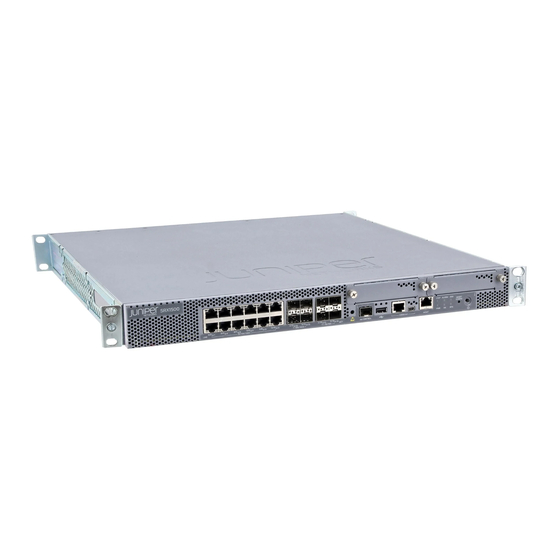
SRX1500 Services Gateway provides campus edge Integrated Security Appliance (ISA) support. The SRX1500 Services Gateway has a modular 1U chassis with twelve 1G Ethernet ports, four 1G SFP ports, and four 10G SFP+ ports. It contains two slots for WAN Physical Interface Modules (PIMs), one slot for an SSD device, and two slots for power supplies. -
Page 22: Srx1500 Services Gateway Cli And J-Web Access
SRX1500 Services Gateway Chassis Overview on page 5 SRX1500 Services Gateway CLI and J-Web Access The SRX1500 Services Gateway runs the Junos operating system (Junos OS). You can use two user interfaces to monitor, configure, troubleshoot, and manage the services gateway: J-Web interface—A Web-based graphical interface that allows you to operate the... -
Page 23: Chassis Components And Descriptions
Understanding the SRX1500 Services Gateway Back Panel on page 8 SRX1500 Services Gateway Chassis Overview The SRX1500 Services Gateway chassis is a rigid sheet metal structure that houses all the other hardware components. The chassis weighs 15 lb. and measures 1.75 in. high, 17.5 in. -
Page 24: Figure 1: Srx1500 Services Gateway Front Panel
SRX1500 Services Gateway Hardware Guide Figure 1: SRX1500 Services Gateway Front Panel Table 3 on page 6 provides information about the front panel components of the services gateway. Table 3: SRX1500 Services Gateway Front Panel Components Callout Component Description 10/100/1000 Twelve 10/100/1000 Base-T ports. -
Page 25: Figure 2: Srx1500 Services Gateway Front Panel Leds
Chapter 2: Chassis Components and Descriptions Table 3: SRX1500 Services Gateway Front Panel Components (continued) Callout Component Description Reset config Returns the services gateway to the factory-default configuration. button LEDs Indicate component and system status and troubleshooting information at a glance. See... -
Page 26: Understanding The Srx1500 Services Gateway Back Panel
SRX1500 Services Gateway Overview on page 3 Documentation SRX1500 Services Gateway Chassis Overview on page 5 Understanding the SRX1500 Services Gateway Back Panel on page 8 Understanding the SRX1500 Services Gateway Back Panel Figure 3 on page 8 shows the back panel of the SRX1500 Services Gateway and Table 5 on page 9 lists the back panel components. -
Page 27: Table 5: Srx1500 Services Gateway Back Panel Components
Four fans for cooling the services gateway and its components. Related SRX1500 Services Gateway Overview on page 3 Documentation SRX1500 Services Gateway Chassis Overview on page 5 Understanding the SRX1500 Services Gateway Front Panel on page 5 Copyright © 2017, Juniper Networks, Inc. - Page 28 SRX1500 Services Gateway Hardware Guide Copyright © 2017, Juniper Networks, Inc.
-
Page 29: Cooling System Description
Understanding the SRX1500 Services Gateway Front Panel on page 5 Understanding the SRX1500 Services Gateway Back Panel on page 8 SRX1500 Services Gateway Cabinet Size and Clearance Requirements on page 29 SRX1500 Services Gateway Cabinet Airflow Requirements on page 30... - Page 30 SRX1500 Services Gateway Hardware Guide Copyright © 2017, Juniper Networks, Inc.
-
Page 31: Power Supply Description
Understanding the SRX1500 Services Gateway Power Supply on page 13 Understanding the SRX1500 Services Gateway Power Supply The power supplies are located on the rear of the chassis. The SRX1500 Services Gateway uses either one AC or one DC power supply unit. -
Page 32: Figure 5: Dc Power Supply For The Srx1500 Services Gateway
SRX1500 Services Gateway AC Power Supply Electrical Specifications on page 33 Documentation Connecting an AC Power Cord to the SRX1500 Services Gateway on page 66 Powering On the SRX1500 Services Gateway on page 68 Powering Off the SRX1500 Services Gateway on page 69... -
Page 33: Site Planning And Specifications
Site Planning and Specifications Planning and Preparing the Site on page 17 Rack Requirements on page 21 Cabinet Requirements on page 29 Power Requirements and Specifications on page 31 Cable Specifications and Pinouts on page 37 Copyright © 2017, Juniper Networks, Inc. - Page 34 SRX1500 Services Gateway Hardware Guide Copyright © 2017, Juniper Networks, Inc.
-
Page 35: Planning And Preparing The Site
SRX1500 Services Gateway Environmental Specifications on page 17 Site Preparation Checklist for the SRX1500 Services Gateway on page 18 General Site Installation Guidelines for the SRX1500 Services Gateway on page 20 SRX1500 Services Gateway Physical Specifications Table 7 on page 17 lists the physical specifications for the services gateway. -
Page 36: Site Preparation Checklist For The Srx1500 Services Gateway
SRX1500 Services Gateway Physical Specifications on page 17 Documentation Site Preparation Checklist for the SRX1500 Services Gateway on page 18 General Site Installation Guidelines for the SRX1500 Services Gateway on page 20 Site Preparation Checklist for the SRX1500 Services Gateway Table 9 on page 18 provides a checklist of tasks you need to perform when preparing a site for installing the SRX1500 Services Gateway. -
Page 37: Rack Requirements
Chapter 5: Planning and Preparing the Site Table 9: Site Preparation Checklist for SRX1500 Services Gateway Installation (continued) Performed Item or Task Additional Information Date Notes Verify that environmental “SRX1500 Services Gateway factors such as temperature Environmental Specifications” and humidity do not exceed on page 17 device tolerances. -
Page 38: General Site Installation Guidelines For The Srx1500 Services Gateway
SRX1500 Services Gateway Hardware Guide Related General Site Installation Guidelines for the SRX1500 Services Gateway on page 20 Documentation SRX1500 Services Gateway Physical Specifications on page 17 SRX1500 Services Gateway Environmental Specifications on page 17 General Site Installation Guidelines for the SRX1500 Services Gateway... -
Page 39: Rack Requirements
SRX1500 Services Gateway Rack-Mounting Requirements and Warnings on page 21 SRX1500 Services Gateway Rack Requirements on page 25 SRX1500 Services Gateway Spacing of Mounting Brackets and Flange Holes on page 25 SRX1500 Services Gateway Clearance Requirements for Airflow and Hardware... - Page 40 Les directives ci-dessous sont destinées à assurer la protection du personnel: Le rack sur lequel est monté le Juniper Networks services gateway doit être fixé à la structure du bâtiment. Si cette unité constitue la seule unité montée en casier, elle doit être placée dans le bas.
- Page 41 Le seguenti direttive vengono fornite per garantire la sicurezza personale: Il Juniper Networks services gateway deve essere installato in un telaio, il quale deve essere fissato alla struttura dell'edificio. Questa unità deve venire montata sul fondo del supporto, se si tratta dell'unica unità...
- Page 42 Para garantizar su seguridad, proceda según las siguientes instrucciones: El Juniper Networks services gateway debe instalarse en un bastidor fijado a la estructura del edificio. Colocar el equipo en la parte inferior del bastidor, cuando sea la única unidad en el mismo.
-
Page 43: Srx1500 Services Gateway Rack Requirements
Chapter 6: Rack Requirements SRX1500 Services Gateway Spacing of Mounting Brackets and Flange Holes on page 25 SRX1500 Services Gateway Clearance Requirements for Airflow and Hardware Maintenance on page 26 SRX1500 Services Gateway Rack Requirements When installing the services gateway in a rack, you must ensure that the rack complies with a 1U (19 in. -
Page 44: Srx1500 Services Gateway Clearance Requirements For Airflow And Hardware Maintenance
SRX1500 Services Gateway Clearance Requirements for Airflow and Hardware Maintenance When planning the installation site for the SRX1500 Services Gateway, you need to allow sufficient clearance around the rack. Consider the following: For the cooling system to function properly, the airflow around the chassis must be unrestricted. -
Page 45: Figure 6: Airflow Through The Chassis
Ports Related SRX1500 Services Gateway Rack-Mounting Requirements and Warnings on page 21 Documentation SRX1500 Services Gateway Rack Requirements on page 25 SRX1500 Services Gateway Spacing of Mounting Brackets and Flange Holes on page 25 Copyright © 2017, Juniper Networks, Inc. - Page 46 SRX1500 Services Gateway Hardware Guide Copyright © 2017, Juniper Networks, Inc.
-
Page 47: Cabinet Requirements
SRX1500 Services Gateway Cabinet Airflow Requirements on page 30 SRX1500 Services Gateway Cabinet Size and Clearance Requirements You can install the SRX1500 Services Gateway in a 19 in. (48.7 cm) cabinet as defined in Cabinets, Racks, Panels, and Associated Equipment (document number EIA-310-D) published by the Electronic Industries Alliance ( http://www.ecaus.org/eia/site/index.html... -
Page 48: Srx1500 Services Gateway Cabinet Airflow Requirements
SRX1500 Services Gateway Hardware Guide SRX1500 Services Gateway Cabinet Airflow Requirements When you mount the SRX1500 Services Gateway in a cabinet, you must ensure that ventilation through the cabinet is sufficient to prevent overheating. Consider the following when planning for chassis cooling: Ensure that the cool air supply you provide through the cabinet can adequately dissipate the thermal output of the services gateway. -
Page 49: Power Requirements And Specifications
SRX1500 Services Gateway Electrical Wiring Guidelines on page 31 SRX1500 Services Gateway Supported AC Power Cords on page 32 SRX1500 Services Gateway AC Power Supply Electrical Specifications on page 33 SRX1500 Services Gateway DC Power Supply Electrical Specifications on page 34... -
Page 50: Srx1500 Services Gateway Supported Ac Power Cords
SRX1500 Services Gateway Supported AC Power Cords on page 32 Documentation SRX1500 Services Gateway AC Power Supply Electrical Specifications on page 33 SRX1500 Services Gateway DC Power Supply Electrical Specifications on page 34 SRX1500 Services Gateway Supported AC Power Cords... -
Page 51: Srx1500 Services Gateway Ac Power Supply Electrical Specifications
Power cords and cables must not block access to services gateway components or drape where people might trip on them. Related SRX1500 Services Gateway AC Power Supply Electrical Specifications on page 33 Documentation SRX1500 Services Gateway DC Power Supply Electrical Specifications on page 34... -
Page 52: Srx1500 Services Gateway Dc Power Supply Electrical Specifications
AC input line frequency 47 to 63 Hz Related SRX1500 Services Gateway DC Power Supply Electrical Specifications on page 34 Documentation SRX1500 Services Gateway DC Power Cable Specifications on page 34 SRX1500 Services Gateway Electrical Wiring Guidelines on page 31... -
Page 53: Power Requirements And Specifications
Related SRX1500 Services Gateway Supported AC Power Cords on page 32 Documentation SRX1500 Services Gateway AC Power Supply Electrical Specifications on page 33 SRX1500 Services Gateway DC Power Supply Electrical Specifications on page 34 Copyright © 2017, Juniper Networks, Inc. - Page 54 SRX1500 Services Gateway Hardware Guide Copyright © 2017, Juniper Networks, Inc.
-
Page 55: Cable Specifications And Pinouts
CHAPTER 9 Cable Specifications and Pinouts RJ-45 Connector Pinouts for the SRX1500 Services Gateway Ethernet Port on page 37 RJ-45 Connector Pinouts for the SRX1500 Services Gateway Console Port on page 38 Mini-USB Connector Pinouts for the SRX1500 Services Gateway Console... -
Page 56: Rj-45 Connector Pinouts For The Srx1500 Services Gateway Console Port
SRX1500 Services Gateway Installation Overview on page 43 RJ-45 Connector Pinouts for the SRX1500 Services Gateway Console Port The SRX1500 Services Gateway has two console ports: an RJ-45 Ethernet port and a mini-USB Type-B port. The port on the front panel labeled CONSOLE is an asynchronous serial interface that accepts an RJ-45 connector. -
Page 57: Cable Specifications And Pinouts
Black Ground Related RJ-45 Connector Pinouts for the SRX1500 Services Gateway Console Port on page 38 Documentation RJ-45 Connector Pinouts for the SRX1500 Services Gateway Ethernet Port on page 37 Understanding the SRX1500 Services Gateway Front Panel on page 5 SRX1500 Services Gateway Installation Overview on page 43 Copyright ©... - Page 58 SRX1500 Services Gateway Hardware Guide Copyright © 2017, Juniper Networks, Inc.
-
Page 59: Initial Installation And Configuration
Unpacking the SRX1500 Services Gateway on page 45 Installing the Rack Mounting Hardware on page 49 Installing the SRX1500 Services Gateway into a Rack on page 51 Connecting the SRX1500 Services Gateway to Ground on page 57 Connecting the SRX1500 Services Gateway to External Devices on page 61... - Page 60 SRX1500 Services Gateway Hardware Guide Copyright © 2017, Juniper Networks, Inc.
-
Page 61: Installation Overview
Installation Overview SRX1500 Services Gateway Installation Overview on page 43 Required Tools and Parts for Installing the SRX1500 Services Gateway on page 44 SRX1500 Services Gateway Installation Overview After you have prepared the site for installation and unpacked the SRX1500 Services Gateway, you are ready to install the device. -
Page 62: Required Tools And Parts For Installing The Srx1500 Services Gateway
Electrostatic discharge (ESD) grounding wrist strap Related SRX1500 Services Gateway Installation Overview on page 43 Documentation Installing the SRX1500 Services Gateway in a Rack on page 51 Preparing the SRX1500 Services Gateway for Rack-Mount Installation on page 49 Copyright © 2017, Juniper Networks, Inc. -
Page 63: Unpacking The Srx1500 Services Gateway
Preparing the SRX1500 Services Gateway for Rack-Mount Installation on page 49 Unpacking the SRX1500 Services Gateway The SRX1500 Services Gateway is shipped in a cardboard carton and secured with foam packing material. The carton also contains an accessory box and quick-start instructions. -
Page 64: Verifying Parts Received With The Srx1500 Services Gateway
Save the shipping carton and packing materials in case you need to move or ship the services gateway at a later time. Related Required Tools and Parts for Unpacking the SRX1500 Services Gateway on page 45 Documentation Verifying Parts Received with the SRX1500 Services Gateway on page 46... -
Page 65: Table 20: Accessory/Upgrade Parts List For The Srx1500 Services Gateway
End User License Agreement Safety Guide Related Required Tools and Parts for Unpacking the SRX1500 Services Gateway on page 45 Documentation Unpacking the SRX1500 Services Gateway on page 45 Preparing the SRX1500 Services Gateway for Rack-Mount Installation on page 49... - Page 66 SRX1500 Services Gateway Hardware Guide Copyright © 2017, Juniper Networks, Inc.
-
Page 67: Installing The Rack Mounting Hardware
Installing the Rack Mounting Hardware Preparing the SRX1500 Services Gateway for Rack-Mount Installation on page 49 Connecting the SRX1500 Services Gateway to the Building Structure on page 50 Preparing the SRX1500 Services Gateway for Rack-Mount Installation You can mount an SRX1500 Services Gateway on four-post (telco) racks, enclosed cabinets, and open-frame racks. -
Page 68: Connecting The Srx1500 Services Gateway To The Building Structure
SRX1500 Services Gateway Hardware Guide Connecting the SRX1500 Services Gateway to the Building Structure Always secure the rack in which you are installing the SRX1500 Services Gateway to the structure of the building. If your geographical area is subject to earthquakes, bolt the rack to the floor. -
Page 69: Installing The Srx1500 Services Gateway Into A Rack
Installing a DC Power Supply on the SRX1500 Services Gateway on page 54 Installing the SRX1500 Services Gateway in a Rack You can front-mount the SRX1500 Services Gateway in a rack. Many types of racks are acceptable, including four-post (telco) racks, enclosed cabinets, and open-frame racks. -
Page 70: Figure 9: Installing The Srx1500 Services Gateway In A Rack
Related Installing an AC Power Supply on the SRX1500 Services Gateway on page 53 Documentation Installing a DC Power Supply on the SRX1500 Services Gateway on page 54... -
Page 71: Installing An Ac Power Supply On The Srx1500 Services Gateway
(see Figure 10 on page 53). Figure 10: Installing an AC Power Supply on the SRX1500 Services Gateway Attach the power cord to the power supply. Use a power cord retainer to hold the power cord in place. -
Page 72: Installing A Dc Power Supply On The Srx1500 Services Gateway
Installing the SRX1500 Services Gateway in a Rack on page 51 Documentation Connecting the SRX1500 Services Gateway to an AC Power Supply on page 65 Connecting an AC Power Cord to the SRX1500 Services Gateway on page 66 Replacing an AC Power Supply on the SRX1500 Services Gateway on page 101... - Page 73 Chapter 13: Installing the SRX1500 Services Gateway into a Rack Using both hands, slide the power supply straight into the chassis until the power supply is fully seated in the chassis slot. The power supply faceplate should be flush with any adjacent power supply faceplate.
-
Page 74: Figure 13: Securing The Power Cables
Installing the SRX1500 Services Gateway in a Rack on page 51 Documentation Installing an AC Power Supply on the SRX1500 Services Gateway on page 53 Connecting the SRX1500 Services Gateway to a DC Power Supply on page 67 Replacing a DC Power Supply on the SRX1500 Services Gateway on page 102... -
Page 75: Connecting The Srx1500 Services Gateway To Ground
CHAPTER 14 Connecting the SRX1500 Services Gateway to Ground Required Tools and Parts for Grounding the SRX1500 Services Gateway on page 57 SRX1500 Services Gateway Grounding Specifications on page 57 Connecting the SRX1500 Services Gateway Grounding Cable on page 58... -
Page 76: Connecting The Srx1500 Services Gateway Grounding Cable
Ring-type, vinyl-insulated TV14-6R lug, or equivalent Related Required Tools and Parts for Grounding the SRX1500 Services Gateway on page 57 Documentation Connecting the SRX1500 Services Gateway Grounding Cable on page 58 Powering On the SRX1500 Services Gateway on page 68... -
Page 77: Connecting The Srx1500 Services Gateway To Ground
Dress the grounding cable and verify that it does not touch or block access to the services gateway components and that it does not drape where people could trip on Related Required Tools and Parts for Grounding the SRX1500 Services Gateway on page 57 Documentation SRX1500 Services Gateway Grounding Specifications on page 57... - Page 78 SRX1500 Services Gateway Hardware Guide Copyright © 2017, Juniper Networks, Inc.
-
Page 79: Connecting The Srx1500 Services Gateway To External Devices
CHAPTER 15 Connecting the SRX1500 Services Gateway to External Devices Required Tools and Parts for Connecting the SRX1500 Services Gateway on page 61 Connecting the SRX1500 Services Gateway to a Network for Out-of-Band Management on page 61 Connecting the SRX1500 Services Gateway to a Management Console on page 62... -
Page 80: Connecting The Srx1500 Services Gateway To A Management Console
Attach an electrostatic discharge (ESD) grounding strap to your bare wrist, and connect the strap to one of the ESD points on the chassis. Plug the RJ-45 end of the cable into the CONSOLE port on the SRX1500 Services Gateway as shown in Figure 16 on page Copyright ©... -
Page 81: Figure 16: Connecting The Srx1500 Services Gateway To A Management
Silicon Labs page. Related Required Tools and Parts for Connecting the SRX1500 Services Gateway on page 61 Documentation Connecting the SRX1500 Services Gateway to a Network for Out-of-Band Management on page 61 Connecting the SRX1500 Services Gateway Grounding Cable on page 58... - Page 82 SRX1500 Services Gateway Hardware Guide Copyright © 2017, Juniper Networks, Inc.
-
Page 83: Providing Power To The Srx1500 Services Gateway
Providing Power to the SRX1500 Services Gateway Connecting the SRX1500 Services Gateway to an AC Power Supply on page 65 Connecting an AC Power Cord to the SRX1500 Services Gateway on page 66 Connecting the SRX1500 Services Gateway to a DC Power Supply on page 67... -
Page 84: Connecting An Ac Power Cord To The Srx1500 Services Gateway
CAUTION: We recommend using a surge protector for the power connection. Related Installing an AC Power Supply on the SRX1500 Services Gateway on page 53 Documentation Connecting an AC Power Cord to the SRX1500 Services Gateway on page 66 Powering On the SRX1500 Services Gateway on page 68... -
Page 85: Connecting The Srx1500 Services Gateway To A Dc Power Supply
Chapter 16: Providing Power to the SRX1500 Services Gateway Powering Off the SRX1500 Services Gateway on page 69 Replacing an AC Power Supply on the SRX1500 Services Gateway on page 101 Connecting the SRX1500 Services Gateway to a DC Power Supply You connect DC power to the services gateway by attaching power cables from the external DC power sources to the terminal studs on the power supply faceplates. -
Page 86: Powering On The Srx1500 Services Gateway
Documentation Powering Off the SRX1500 Services Gateway on page 69 Installing a DC Power Supply on the SRX1500 Services Gateway on page 54 Replacing a DC Power Supply on the SRX1500 Services Gateway on page 102 Powering On the SRX1500 Services Gateway To power on the services gateway: Ensure that you have connected the power supply to the device. -
Page 87: Powering Off The Srx1500 Services Gateway
Powering Off the SRX1500 Services Gateway on page 69 Documentation Connecting the SRX1500 Services Gateway to an AC Power Supply on page 65 Connecting an AC Power Cord to the SRX1500 Services Gateway on page 66 Connecting the SRX1500 Services Gateway to a DC Power Supply on page 67... - Page 88 NOTE: The fans in the power supply continue to rotate even after you power off the SRX1500 Services Gateway. To stop the fans, remove the power cord from the power supply. The fans stop in a few seconds. After a power supply is turned on, it can take up to 60 seconds for status indicators—such...
-
Page 89: Performing The Initial Configuration
Configuring the SRX1500 Services Gateway Using the CLI on page 78 SRX1500 Services Gateway Software Configuration Overview The SRX1500 Services Gateway is shipped with Junos OS preinstalled and ready to be configured when the services gateway is powered on. If you are setting up the services gateway for the first time, use the command-line interface (CLI) to perform the initial configuration. -
Page 90: Viewing Srx1500 Services Gateway Factory-Default Settings
Accessing J-Web on the SRX1500 Services Gateway on page 77 Configuring the SRX1500 Services Gateway Using J-Web on page 72 Accessing the CLI on the SRX1500 Services Gateway on page 77 Viewing SRX1500 Services Gateway Factory-Default Settings To view the factory-default configuration of the services gateway using the CLI: Log in as the root user and provide your credentials. -
Page 91: Cli
0 family inet address address/prefix-length Configure the default route. [edit] root@# set routing-options static route 0.0.0.0/0 next-hop gateway Enable Web access to launch J-Web. [edit] root@# set system services web-management http Commit the configuration changes. [edit] root@# commit Copyright © 2017, Juniper Networks, Inc. -
Page 92: Configuring Interfaces, Zones, And Policies With J-Web
SRX1500 Services Gateway Hardware Guide Configuring Interfaces, Zones, and Policies with J-Web You can configure hostnames, interfaces, zones, and security policies using J-Web. Before you begin: Ensure you have configured the IP address, root authentication, and default route. See “Configuring Root Authentication and the Management Interface from the CLI” on page Enable HTTP on the device to access J-Web. -
Page 93: Configuring Interfaces
In the Main tab, enter trust for zone name and enter the description. Set the zone type to Security Select the interfaces listed under Available and move them under Selected. Click A message appears after your configuration changes are validated successfully. Copyright © 2017, Juniper Networks, Inc. -
Page 94: Configuring Security Policies
SRX1500 Services Gateway Hardware Guide Click Select to apply the configuration changes. Commit Options>Commit A message appears after your configuration changes are applied successfully. Click Repeat Step through Step and assign another interface to an untrust zone. You have successfully configured interfaces in a trust zone and in an untrust zone. -
Page 95: Accessing J-Web On The Srx1500 Services Gateway
Related SRX1500 Services Gateway Software Configuration Overview on page 71 Documentation Configuring the SRX1500 Services Gateway Using J-Web on page 72 Accessing the CLI on the SRX1500 Services Gateway To access the CLI on the SRX1500 Services Gateway: Plug one end of the Ethernet cable into the RJ-45 to DB-9 serial port adapter supplied with your services gateway. -
Page 96: Connecting To The Srx1500 Services Gateway From The Cli Remotely
Power on the services gateway. You can start performing initial software configuration on the services gateway after the device is up. Related Configuring the SRX1500 Services Gateway Using the CLI on page 78 Documentation SRX1500 Services Gateway Software Configuration Overview on page 71... - Page 97 Configure the IP address and prefix length for the services gateway Ethernet interface. [edit] admin# set interfaces fxp0 unit 0 family inet address address/prefix-length Configure the traffic interface. [edit] Copyright © 2017, Juniper Networks, Inc.
- Page 98 SRX1500 Services Gateway Hardware Guide admin# set interfaces ge-0/0/0 unit 0 family inet address address/prefix-length admin# set interfaces ge-0/0/1 unit 0 family inet address address/prefix-length NOTE: The ge-0/0/0 interface is for the LAN, and the ge-0/0/1 interface is for the ISP.
- Page 99 { interactive-commands any; security { policies { from-zone trust to-zone untrust { policy trust-pol { match { source-address any; destinataion-address any; application any; then { permit; from-zone untrust to-zone trust { policy untrust-pol { Copyright © 2017, Juniper Networks, Inc.
- Page 100 SRX1500 Services Gateway Hardware Guide match { source-address any; destinataion-address any; application any; then { permit; zones { security-zone trust { interfaces { ge-0/0/0.0; security-zone untrust { interfaces { ge-0/0/1.0; interfaces { ge-0/0/0 { unit 0 { family inet { address 9.0.0.254/8;...
- Page 101 URL http://<device management IP address>. The J-Web login page is displayed. This indicates that you have successfully completed the initial configuration, and your SRX1500 Services Gateway is ready for use. Related Configuring the SRX1500 Services Gateway Using J-Web on page 72 Documentation Copyright © 2017, Juniper Networks, Inc.
- Page 102 SRX1500 Services Gateway Hardware Guide Copyright © 2017, Juniper Networks, Inc.
-
Page 103: Maintaining And Troubleshooting Components
PART 4 Maintaining and Troubleshooting Components Maintaining Components on page 87 Troubleshooting Components on page 89 Copyright © 2017, Juniper Networks, Inc. - Page 104 SRX1500 Services Gateway Hardware Guide Copyright © 2017, Juniper Networks, Inc.
-
Page 105: Maintaining Components
CHAPTER 18 Maintaining Components Required Tools and Parts for Maintaining the SRX1500 Services Gateway on page 87 Routine Maintenance Procedures for the SRX1500 Services Gateway on page 87 Maintaining the SRX1500 Services Gateway Power Supply on page 88 Required Tools and Parts for Maintaining the SRX1500 Services Gateway... -
Page 106: Maintaining The Srx1500 Services Gateway Power Supply
Related Required Tools and Parts for Maintaining the SRX1500 Services Gateway on page 87 Documentation Routine Maintenance Procedures for the SRX1500 Services Gateway on page 87 Troubleshooting Resources for the SRX1500 Services Gateway Overview on page 89 Copyright ©... -
Page 107: Troubleshooting Components
Gateway on page 90 Troubleshooting the Power System on the SRX1500 Services Gateway on page 91 Using the RESET CONFIG Button on the SRX1500 Services Gateway on page 94 Changing the RESET CONFIG Button Behavior on the SRX1500 Services Gateway on page 94... -
Page 108: Troubleshooting Chassis And Interface Alarm Messages On The Srx1500 Services Gateway
SRX1500 Services Gateway Hardware Guide Troubleshooting Chassis and Interface Alarm Messages on the SRX1500 Services Gateway Problem Description: When the services gateway detects an alarm condition, the alarm LED on the interfaces glows red or yellow on the front panel as appropriate. To view a more detailed description of the alarm cause, issue the command. -
Page 109: Troubleshooting The Power System On The Srx1500 Services Gateway
Documentation Troubleshooting the Power System on the SRX1500 Services Gateway on page 91 Using the RESET CONFIG Button on the SRX1500 Services Gateway on page 94 Changing the RESET CONFIG Button Behavior on the SRX1500 Services Gateway on page 94... -
Page 110: Table 23: Pwr Led Description
SRX1500 Services Gateway Hardware Guide Table 23: PWR LED Description Diagnosis Possible Cause and Corrective LED Status LED State Meaning Action Green The services gateway Normal indication. No action is is receiving power, required. and all AC and/or DC power supply units (PSUs) are working properly. - Page 111 Related Troubleshooting Resources for the SRX1500 Services Gateway Overview on page 89 Documentation Using the RESET CONFIG Button on the SRX1500 Services Gateway on page 94 Changing the RESET CONFIG Button Behavior on the SRX1500 Services Gateway on page 94...
-
Page 112: Using The Reset Config Button On The Srx1500 Services Gateway
94 Changing the RESET CONFIG Button Behavior on the SRX1500 Services Gateway You can change the default operation of the RESET CONFIG button of the SRX1500 Services Gateway by limiting how the button resets the services gateway: To prevent the RESET CONFIG button from setting the services gateway to the factory-default configuration and deleting all other configurations, enter the following command. - Page 113 To return the function of the RESET CONFIG button to its default behavior, remove the statement from the services gateway configuration. config-button Related Troubleshooting Resources for the SRX1500 Services Gateway Overview on page 89 Documentation Using the RESET CONFIG Button on the SRX1500 Services Gateway on page 94 Copyright © 2017, Juniper Networks, Inc.
- Page 114 SRX1500 Services Gateway Hardware Guide Copyright © 2017, Juniper Networks, Inc.
-
Page 115: Replacing Components
PART 5 Replacing Components Overview of Replacing Components on page 99 Replacing Power Supply Components on page 101 Contacting Customer Support on page 105 Copyright © 2017, Juniper Networks, Inc. - Page 116 SRX1500 Services Gateway Hardware Guide Copyright © 2017, Juniper Networks, Inc.
-
Page 117: Overview Of Replacing Components
Field-replaceable units (FRUs) are components that you can replace at your site. The power supplies are the only FRUs on the SRX1500 Services Gateway. The power supplies (if redundant) are hot-swappable. You can remove and replace the power supply without powering off the services gateway or disrupting the services gateway functions. - Page 118 SRX1500 Services Gateway Hardware Guide Replacing a DC Power Supply on the SRX1500 Services Gateway on page 102 Copyright © 2017, Juniper Networks, Inc.
-
Page 119: Replacing Power Supply Components
CHAPTER 21 Replacing Power Supply Components Replacing an AC Power Supply on the SRX1500 Services Gateway on page 101 Replacing a DC Power Supply on the SRX1500 Services Gateway on page 102 Replacing an AC Power Supply on the SRX1500 Services Gateway... -
Page 120: Replacing A Dc Power Supply On The Srx1500 Services Gateway
SRX1500 Services Gateway AC Power Supply Electrical Specifications on page 33 Replacing a DC Power Supply on the SRX1500 Services Gateway Removing a DC Power Supply Cable from the SRX1500 Services Gateway on page 103 Removing a DC Power Supply on the SRX1500 Services Gateway on page 103... -
Page 121: Removing A Dc Power Supply On The Srx1500 Services Gateway
Chapter 21: Replacing Power Supply Components Removing a DC Power Supply Cable from the SRX1500 Services Gateway To remove a power supply cable connected to a DC power supply: Attach an electrostatic discharge (ESD) grounding strap to your bare wrist and connect the strap to an approved site ESD grounding point. - Page 122 Carefully move the power cables out of the way. Push the Tab latch on the right edge of the power supply to the left. Pull the power supply straight out of the chassis. Figure 18: Removing a DC Power Supply from the SRX1500 Services Gateway Related...
-
Page 123: Contacting Customer Support
Contacting Customer Support Once you have located the serial numbers of the device or component, you can return the device or component for repair or replacement. For this, you need to contact Juniper Networks Technical Assistance Center (JTAC). You can contact JTAC 24 hours a day, 7 days a week, using any of the following methods: On the Web: Using the Case Manager link at http://www.juniper.net/support/... -
Page 124: Returning A Srx1500 Services Gateway Component To Juniper Networks
Information You Might Need to Supply to JTAC on page 108 Returning a SRX1500 Services Gateway Component to Juniper Networks To return an SRX1500 Services Gateway or component to Juniper Networks for repair or replacement: Determine the part number and serial number of the services gateway or component. -
Page 125: Listing The Srx1500 Services Gateway Component Details With The Cli
Before contacting Juniper Networks to request a Return Materials Authorization (RMA), you must find the serial number on the SRX1500 Services Gateway or component. To list all of the SRX1500 Services Gateway components and their serial numbers, enter the following command-line interface (CLI) command: user@host>... -
Page 126: Information You Might Need To Supply To Jtac
Locating the SRX1500 Services Gateway Chassis Serial Number and Agency Labels on page 106 Listing the SRX1500 Services Gateway Component Details with the CLI on page 107 Packing the SRX1500 Services Gateway for Shipment on page 109 Required Tools and Parts for Packing the SRX1500 Services Gateway... -
Page 127: Packing The Srx1500 Services Gateway For Shipment
To pack the SRX1500 Services Gateway for shipment: Retrieve the shipping carton and packing materials in which the services gateway was originally shipped. If you do not have these materials, contact your Juniper Networks representative about approved packaging materials. Attach an electrostatic discharge (ESD) grounding strap to your bare wrist and connect the strap to the ESD point on the chassis or to an outside ESD point if the device is disconnected from earth ground. -
Page 128: Packing Srx1500 Services Gateway Components For Shipment
106 Information You Might Need to Supply to JTAC on page 108 Required Tools and Parts for Packing the SRX1500 Services Gateway on page 108 Packing SRX1500 Services Gateway Components for Shipment on page 110 Packing SRX1500 Services Gateway Components for Shipment... -
Page 129: Safety Guidelines
Laser and LED Safety Guidelines and Warnings on page 123 Maintenance and Operational Safety Guidelines and Warnings on page 127 Electrical Safety Guidelines and Warnings on page 135 Agency Approvals and Regulatory Compliance Information on page 147 Copyright © 2017, Juniper Networks, Inc. - Page 130 SRX1500 Services Gateway Hardware Guide Copyright © 2017, Juniper Networks, Inc.
-
Page 131: General Safety Information
CHAPTER 23 General Safety Information SRX1500 Services Gateway Definition of Safety Warnings Levels on page 113 SRX1500 Services Gateway General Safety Guidelines and Warnings on page 115 SRX1500 Services Gateway Safety Requirements, Warnings, and Guidelines on page 116 Restricted Access Area Warnings on page 116... - Page 132 Innan du utför arbete på någon utrustning måste du vara medveten om farorna med elkretsar och känna till vanligt förfarande för att förebygga skador. Related SRX1500 Services Gateway General Safety Guidelines and Warnings on page 115 Documentation Copyright © 2017, Juniper Networks, Inc.
-
Page 133: Srx1500 Services Gateway General Safety Guidelines And Warnings
Chapter 23: General Safety Information SRX1500 Services Gateway Safety Requirements, Warnings, and Guidelines on page 116 General Laser Safety Guidelines on page 123 SRX1500 Services Gateway General Safety Guidelines and Warnings The following guidelines help ensure your safety and protect the services gateway from damage. -
Page 134: Srx1500 Services Gateway Safety Requirements, Warnings, And Guidelines
Providing an exhaustive set of guidelines for working with electrical equipment is beyond the scope of this guide. Related SRX1500 Services Gateway Definition of Safety Warnings Levels on page 113 Documentation SRX1500 Services Gateway General Safety Guidelines and Warnings on page 115... -
Page 135: Qualified Personnel Warnings
Related SRX1500 Services Gateway Definition of Safety Warnings Levels on page 113 Documentation SRX1500 Services Gateway General Safety Guidelines and Warnings on page 115 SRX1500 Services Gateway Safety Requirements, Warnings, and Guidelines on page 116... -
Page 136: Gateway
Varning! Denna utrustning ska endast installeras och bytas ut av utbildad och kvalificerad personal. Related SRX1500 Services Gateway Definition of Safety Warnings Levels on page 113 Documentation SRX1500 Services Gateway General Safety Guidelines and Warnings on page 115 SRX1500 Services Gateway Safety Requirements, Warnings, and Guidelines on page 116... - Page 137 Figure 19: Placing a Component into an Electrostatic Bag Related SRX1500 Services Gateway Definition of Safety Warnings Levels on page 113 Documentation SRX1500 Services Gateway General Safety Guidelines and Warnings on page 115 SRX1500 Services Gateway Safety Requirements, Warnings, and Guidelines on page 116...
- Page 138 SRX1500 Services Gateway Hardware Guide Copyright © 2017, Juniper Networks, Inc.
-
Page 139: Fire Safety Requirements
SRX1500 Services Gateway Fire Safety Requirements and Fire Suppression Equipment on page 121 SRX1500 Services Gateway Fire Safety Requirements and Fire Suppression Equipment In the event of a fire emergency involving devices and other network equipment, the safety of people is the primary concern. Establish procedures for protecting people in the event of a fire emergency, provide safety training, and properly provision fire control equipment and fire extinguishers. - Page 140 To keep warranties effective, do not use a dry chemical fire extinguisher to control a fire at or near a Juniper Networks services gateway. If a dry chemical fire extinguisher is used, the unit is no longer eligible for coverage under a service agreement.
-
Page 141: Laser And Led Safety Guidelines And Warnings
Related Class 1 Laser Warnings on page 124 Documentation Class 1 LED Product Warnings on page 124 Laser Beam Warnings on page 125 Radiation from Open Port Apertures Warnings on page 126 Copyright © 2017, Juniper Networks, Inc. -
Page 142: Class 1 Laser Warnings
SRX1500 Services Gateway Hardware Guide Class 1 Laser Warnings WARNING: Class 1 laser product. Waarschuwing Klasse-1 laser produkt. Varoitus Luokan 1 lasertuote. Attention Produit laser de classe I. Warnung Laserprodukt der Klasse 1. Avvertenza Prodotto laser di Classe 1. Advarsel Laserprodukt av klasse 1. -
Page 143: Laser Beam Warnings
Related General Laser Safety Guidelines on page 123 Documentation Class 1 Laser Warnings on page 124 Class 1 LED Product Warnings on page 124 Radiation from Open Port Apertures Warnings on page 126 Copyright © 2017, Juniper Networks, Inc. -
Page 144: Radiation From Open Port Apertures Warnings
SRX1500 Services Gateway Hardware Guide Radiation from Open Port Apertures Warnings WARNING: Because invisible radiation can be emitted from the aperture of the port when no fiber cable is connected, avoid exposure to radiation and do not stare into open apertures. -
Page 145: Maintenance And Operational Safety Guidelines And Warnings
Warnung Bei Einsetzen einer falschen Batterie besteht Explosionsgefahr. Ersetzen Sie die Batterie nur durch den gleichen oder vom Hersteller empfohlenen Batterietyp. Entsorgen Sie die benutzten Batterien nach den Anweisungen des Herstellers. Copyright © 2017, Juniper Networks, Inc. -
Page 146: Lightning Activity Warnings
SRX1500 Services Gateway Hardware Guide Avvertenza Pericolo di esplosione se la batteria non è installata correttamente. Sostituire solo con una di tipo uguale o equivalente, consigliata dal produttore. Eliminare le batterie usate secondo le istruzioni del produttore. Advarsel Det kan være fare for eksplosjon hvis batteriet skiftes på feil måte. -
Page 147: Jewelry Removal Warnings
Warnung Vor der Arbeit an Geräten, die an das Netz angeschlossen sind, jeglichen Schmuck (einschließlich Ringe, Ketten und Uhren) abnehmen. Metallgegenstände erhitzen sich, wenn sie an das Netz und die Erde Copyright © 2017, Juniper Networks, Inc. -
Page 148: Operating Temperature Warnings
SRX1500 Services Gateway Hardware Guide angeschlossen werden, und können schwere Verbrennungen verursachen oder an die Anschlußklemmen angeschweißt werden. Avvertenza Prima di intervenire su apparecchiature collegate alle linee di alimentazione, togliersi qualsiasi monile (inclusi anelli, collane, braccialetti ed orologi). Gli oggetti metallici si riscaldano quando sono collegati tra punti di alimentazione e massa: possono causare ustioni gravi oppure il metallo può... - Page 149 Chapter 26: Maintenance and Operational Safety Guidelines and Warnings Waarschuwing Om te voorkomen dat welke services gateway van de Juniper Networks services gateway dan ook oververhit raakt, dient u deze niet te bedienen op een plaats waar de maximale aanbevolen ο...
-
Page 150: Product Disposal Warnings
SRX1500 Services Gateway Hardware Guide inskränks genom att se till att det finns fritt utrymme på minst 15,2 cm omkring ventilationsöppningarna. Related Battery-Handling Warnings on page 127 Documentation Lightning Activity Warnings on page 128 Jewelry Removal Warnings on page 129... - Page 151 Chapter 26: Maintenance and Operational Safety Guidelines and Warnings Operating Temperature Warnings on page 130 Copyright © 2017, Juniper Networks, Inc.
- Page 152 SRX1500 Services Gateway Hardware Guide Copyright © 2017, Juniper Networks, Inc.
-
Page 153: Electrical Safety Guidelines And Warnings
Install the services gateway in compliance with the following local, national, or international electrical codes: United States—National Fire Protection Association (NFPA 70), United States National Electrical Code Canada—Canadian Electrical Code, Part 1, CSA C22.1 Copyright © 2017, Juniper Networks, Inc. -
Page 154: Grounded Equipment Warning
SRX1500 Services Gateway Hardware Guide Other countries—International Electromechanical Commission (IEC) 60364, Part 1 through Part 7 Evaluated to the TN power system Locate the emergency power-off switch for the room in which you are working so that if an electrical accident occurs, you can quickly turn off the power. -
Page 155: Backplane Energy Hazard Warning
¡Atención! Esta unidad tiene más de una conexión de suministros de alimentación; para eliminar la alimentación por completo, deben desconectarse completamente todas las conexiones. Copyright © 2017, Juniper Networks, Inc. -
Page 156: Power Disconnection Warning
SRX1500 Services Gateway Hardware Guide Varning! Denna enhet har mer än en strömförsörjningsanslutning; alla anslutningar måste vara helt avlägsnade innan strömtillförseln till enheten är fullständigt bruten. Power Disconnection Warning WARNING: Before working on the services gateway or near power supplies, unplug the power cord from an AC-powered services gateway;... -
Page 157: Tn Power Warning
Varoitus Käytä vain kuparijohtimia. Attention Utilisez uniquement des conducteurs en cuivre. Warnung Verwenden Sie ausschließlich Kupferleiter. Avvertenza Usate unicamente dei conduttori di rame. Advarsel Bruk bare kobberledninger. Aviso Utilize apenas fios condutores de cobre. Copyright © 2017, Juniper Networks, Inc. -
Page 158: Ac Power Electrical Safety Guidelines
SRX1500 Services Gateway Hardware Guide ¡Atención! Emplee sólo conductores de cobre. Varning! Använd endast ledare av koppar. Related In Case of Electrical Accident on page 135 Documentation AC Power Electrical Safety Guidelines on page 140 DC Power Electrical Safety Guidelines on page 141... -
Page 159: Dc Power Electrical Safety Guidelines
NEC ANSI/NFPA70. Ensure that the polarity of the DC input wiring is correct. Under certain conditions, connections with reversed polarity might trip the primary circuit breaker or damage the equipment. Copyright © 2017, Juniper Networks, Inc. -
Page 160: Dc Power Disconnection Warning
SRX1500 Services Gateway Hardware Guide For personal safety, connect the green and yellow wire to safety (earth) ground at both the services gateway and the supply side of the DC wiring. The marked input voltage of -48 VDC for a DC-powered services gateway is the nominal voltage associated with the battery circuit, and any higher voltages are only to be associated with float voltages for the charging function. -
Page 161: Dc Power Grounding Requirements And Warning
Attention Lors de l'installation de l'appareil, la mise à la terre doit toujours être connectée en premier et déconnectée en dernier. Warnung Der Erdanschluß muß bei der Installation der Einheit immer zuerst hergestellt und zuletzt abgetrennt werden. Copyright © 2017, Juniper Networks, Inc. -
Page 162: Dc Power Wiring Sequence Warning
SRX1500 Services Gateway Hardware Guide Avvertenza In fase di installazione dell'unità, eseguire sempre per primo il collegamento a massa e disconnetterlo per ultimo. Advarsel Når enheten installeres, må jordledningen alltid tilkobles først og frakobles sist. Aviso Ao instalar a unidade, a ligação à terra deverá ser sempre a primeira a ser ligada, e a última a ser desligada. -
Page 163: Dc Power Wiring Terminations Warning
Varoitus Jos säikeellinen johdin on tarpeen, käytä hyväksyttyä johdinliitäntää, esimerkiksi suljettua silmukkaa tai kourumaista liitäntää, jossa on ylöspäin käännetyt kiinnityskorvat. Tällaisten liitäntöjen tulee olla kooltaan johtimiin sopivia ja niiden tulee puristaa yhteen sekä eristeen että johdinosan. Copyright © 2017, Juniper Networks, Inc. - Page 164 SRX1500 Services Gateway Hardware Guide Attention Quand des fils torsadés sont nécessaires, utiliser des douilles terminales homologuées telles que celles à circuit fermé ou du type à plage ouverte avec cosses rebroussées. Ces douilles terminales doivent être de la taille qui convient aux fils et doivent être refermées sur la gaine isolante et sur le conducteur.
-
Page 165: Agency Approvals And Regulatory Compliance Information
Agency Approvals and Regulatory Compliance Information SRX1500 Services Gateway Agency Approvals on page 147 SRX1500 Services Gateway Acoustic Noise Compliance Statements on page 148 SRX1500 Services Gateway EMC Requirements on page 148 SRX1500 Services Gateway Agency Approvals The services gateway complies with the following standards: Safety CAN/CSA-C22.2 No.60950-1 (2007) Information Technology Equipment... -
Page 166: Srx1500 Services Gateway Acoustic Noise Compliance Statements
Documentation SRX1500 Services Gateway EMC Requirements on page 148 SRX1500 Services Gateway General Safety Guidelines and Warnings on page 115 SRX1500 Services Gateway Acoustic Noise Compliance Statements The maximum emitted sound pressure level is 70 dB(A) or less per EN ISO 7779. -
Page 167: European Community
Related SRX1500 Services Gateway Agency Approvals on page 147 Documentation SRX1500 Services Gateway Acoustic Noise Compliance Statements on page 148 SRX1500 Services Gateway General Safety Guidelines and Warnings on page 115 Copyright © 2017, Juniper Networks, Inc. - Page 168 SRX1500 Services Gateway Hardware Guide Copyright © 2017, Juniper Networks, Inc.
Need help?
Do you have a question about the SRX1500 and is the answer not in the manual?
Questions and answers