
Related Manuals for Juniper SRX100B


Summary of Contents for Juniper SRX100B
- Page 1 SRX100 Services Gateway Hardware Guide for B and H Model Numbers Modified: 2015-06-17 Copyright © 2015, Juniper Networks, Inc.
- Page 2 END USER LICENSE AGREEMENT The Juniper Networks product that is the subject of this technical documentation consists of (or is intended for use with) Juniper Networks software. Use of such software is subject to the terms and conditions of the End User License Agreement (“EULA”) posted at http://www.juniper.net/support/eula.html.
-
Page 3: Table Of Contents
SRX100 Services Gateway Cabinet Requirements ......25 SRX100 Services Gateway Rack Requirements ......26 Copyright © 2015, Juniper Networks, Inc. - Page 4 Powering On the SRX100 Services Gateway ......66 Powering Off the SRX100 Services Gateway ......67 Copyright © 2015, Juniper Networks, Inc.
- Page 5 Gateway ............103 Juniper Networks Technical Assistance Center ......103...
- Page 6 Requirements ..........146 Copyright © 2015, Juniper Networks, Inc.
- Page 7 Index ............149 Copyright © 2015, Juniper Networks, Inc.
- Page 8 SRX100 Services Gateway Hardware Guide for B and H Model Numbers viii Copyright © 2015, Juniper Networks, Inc.
-
Page 9: List Of Figures
Labels ............110 Copyright © 2015, Juniper Networks, Inc. - Page 10 General Safety Guidelines and Warnings ......115 Figure 18: Placing a Component into an Electrostatic Bag ....120 Copyright © 2015, Juniper Networks, Inc.
- Page 11 Installation Overview ..........39 Table 20: Installation Process Order for the SRX100 Services Gateway ..40 Copyright © 2015, Juniper Networks, Inc.
- Page 12 Table 36: Services Gateway Power LED Status ......101 Copyright © 2015, Juniper Networks, Inc.
-
Page 13: About The Documentation
® To obtain the most current version of all Juniper Networks technical documentation, see the product documentation page on the Juniper Networks website at http://www.juniper.net/techpubs/ If the information in the latest release notes differs from the information in the documentation, follow the product Release Notes. -
Page 14: Table 1: Notice Icons
RFC 1997, BGP Communities Attribute Italic text like this Represents variables (options for which Configure the machine’s domain name: you substitute a value) in commands or [edit] configuration statements. root@# set system domain-name domain-name Copyright © 2015, Juniper Networks, Inc. -
Page 15: Documentation Feedback
We encourage you to provide feedback, comments, and suggestions so that we can improve the documentation. You can provide feedback by using either of the following methods: Online feedback rating system—On any page at the Juniper Networks Technical Documentation site at , simply click the http://www.juniper.net/techpubs/index.html... -
Page 16: Requesting Technical Support
7 days a week, 365 days a year. Self-Help Online Tools and Resources For quick and easy problem resolution, Juniper Networks has designed an online self-service portal called the Customer Support Center (CSC) that provides you with the following features: Find CSC offerings: http://www.juniper.net/customers/support/... - Page 17 About the Documentation For international or direct-dial options in countries without toll-free numbers, see http://www.juniper.net/support/requesting-support.html Copyright © 2015, Juniper Networks, Inc. xvii...
- Page 18 SRX100 Services Gateway Hardware Guide for B and H Model Numbers xviii Copyright © 2015, Juniper Networks, Inc.
-
Page 19: Overview
PART 1 Overview System Overview on page 3 Hardware Component Overview on page 7 Chassis Description on page 13 Copyright © 2015, Juniper Networks, Inc. - Page 20 SRX100 Services Gateway Hardware Guide for B and H Model Numbers Copyright © 2015, Juniper Networks, Inc.
-
Page 21: System Overview
Accessing the SRX100 Services Gateway on page 4 About the SRX100 Services Gateway The Juniper Networks SRX100 Services Gateway offers features that provide complete functionality and flexibility for delivering secure Internet and intranet access. The services gateway offers stable, reliable, and efficient IP routing in addition to switching support and LAN connectivity. -
Page 22: Accessing The Srx100 Services Gateway
The J-Web interface provides access to all Junos OS functionality and features. Junos OS command-line interface (CLI): Juniper Networks command shell that runs on top of a UNIX-based operating system kernel. The CLI is a straightforward command interface. -
Page 23: Table 4: Srx100 Services Gateway Hardware Features
Memory Version” on page Related SRX100 Services Gateway Description on page 3 Documentation SRX100 Services Gateway Specifications on page 24 Upgrading the SRX100 Services Gateway Low Memory Version to a High Memory Version on page 90 Copyright © 2015, Juniper Networks, Inc. - Page 24 SRX100 Services Gateway Hardware Guide for B and H Model Numbers Copyright © 2015, Juniper Networks, Inc.
-
Page 25: Hardware Component Overview
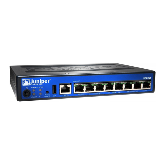
Figure 1 on page 7 correspond to the numbers in Table 5 on page Figure 1: SRX100 Services Gateway Front Panel LEDs Table 5 on page 8 lists the LED indicators on the SRX100 Services Gateway front panel. Copyright © 2015, Juniper Networks, Inc. -
Page 26: Table 5: Srx100 Services Gateway Front Panel Leds
Solid amber indicates that the power button has been pressed and quickly released. The device is gracefully shutting down. Off indicates that the device is not receiving power. Copyright © 2015, Juniper Networks, Inc. -
Page 27: Srx100 Services Gateway Ethernet Port Leds
SRX100 Services Gateway Ethernet Port LEDs On the SRX100 Services Gateway, each Fast Ethernet port has one functional LED on the left side that indicates Link and Activity. In Figure 2 on page 10, this LED is marked as Copyright © 2015, Juniper Networks, Inc. -
Page 28: Srx100 Services Gateway Power Supply
SRX100 Services Gateway Power Supply The power supply for the SRX100 Services Gateway is external. You must use the power supply adapter provided by Juniper Networks to provide power to the services gateway. Related SRX100 Services Gateway Specifications on page 24... -
Page 29: Srx100 Services Gateway Boot Devices And Dual-Root Partitioning Scheme
(strongly recommended) or retain the existing single-root partitioning. For instructions on upgrading to Junos OS Release 10.0, see the following topics: Initial Configuration for Security Devices Copyright © 2015, Juniper Networks, Inc. - Page 30 SRX100 Services Gateway Hardware Guide for B and H Model Numbers Monitoring and Troubleshooting for Security Devices Related Installation Overview for the SRX100 Services Gateway on page 40 Documentation SRX100 Services Gateway Software Configuration Overview on page 69 Copyright © 2015, Juniper Networks, Inc.
-
Page 31: Chassis Description
Table 7 on page 13 lists the front panel components of the services gateway. Table 7: SRX100 Services Gateway Front Panel Components Number Component Power button LEDs: Alarm, Status, Power, HA Reset Config button Copyright © 2015, Juniper Networks, Inc. -
Page 32: Srx100 Services Gateway Back Panel
Table 8 on page 14 lists the components available on the back panel of the SRX100 Services Gateway. Table 8: SRX100 Services Gateway Back Panel Number Component Lock Grounding point Cable tie holder Power supply point Copyright © 2015, Juniper Networks, Inc. -
Page 33: Srx100 Services Gateway Built-In Interfaces
Provide link speeds of To forward incoming data 10/100 Mbps packets to the device. Operate in full-duplex and To receive outgoing data half-duplex modes packets from the device. Support flow control Support autonegotiation Support autosensing Copyright © 2015, Juniper Networks, Inc. - Page 34 Related SRX100 Services Gateway Specifications on page 24 Documentation SRX100 Services Gateway Front Panel and Back Panel Views on page 13 Copyright © 2015, Juniper Networks, Inc.
- Page 35 Chapter 3: Chassis Description SRX100 Services Gateway LEDs on page 7 SRX100 Services Gateway Boot Devices and Dual-Root Partitioning Scheme on page 11 SRX100 Services Gateway Power Supply on page 10 Copyright © 2015, Juniper Networks, Inc.
- Page 36 SRX100 Services Gateway Hardware Guide for B and H Model Numbers Copyright © 2015, Juniper Networks, Inc.
-
Page 37: Site Planning And Specifications
PART 2 Site Planning and Specifications Planning and Preparing the Site on page 21 Power Requirements and Specifications on page 29 Cable Specifications and Pinouts on page 33 Copyright © 2015, Juniper Networks, Inc. - Page 38 SRX100 Services Gateway Hardware Guide for B and H Model Numbers Copyright © 2015, Juniper Networks, Inc.
-
Page 39: Planning And Preparing The Site
Table 10: Site Preparation Checklist for Services Gateway Installation Additional Item or Task Information Performed By Date Notes Environment Verify that “SRX100 environmental factors Services such as temperature Gateway and humidity do not Specifications” exceed device on page 24 tolerances. Power Copyright © 2015, Juniper Networks, Inc. - Page 40 Installation” on structure. page 47 Cabinet Requirements Verify that your “SRX100 cabinet meets the Services minimum Gateway requirements. Cabinet Requirements” Plan the cabinet on page 25 location, including required space clearances. Wall Installation Copyright © 2015, Juniper Networks, Inc.
- Page 41 General Site Guidelines for Installing the SRX100 Services Gateway on page 24 SRX100 Services Gateway Cabinet Requirements on page 25 SRX100 Services Gateway Rack Requirements on page 26 Clearance Requirements for Airflow and Hardware Maintenance of the SRX100 Services Gateway on page 27 Copyright © 2015, Juniper Networks, Inc.
-
Page 42: General Site Guidelines For Installing The Srx100 Services Gateway
8.5 in. (216 mm) Chassis depth 5.79 in. (147 mm) Chassis weight 1.86 lb (844 g) Average power consumption SRX100 Services Gateway Low Memory model: 10 watts SRX100 Services Gateway High Memory model: 10 watts Copyright © 2015, Juniper Networks, Inc. -
Page 43: Srx100 Services Gateway Cabinet Requirements
SRX100 Services Gateway Cabinet Requirements The SRX100 Services Gateway can be installed in a standard 31.5 in. (800 mm) or larger enclosed cabinet. Table 12 on page 26 provides the details on cabinet size, clearance, and airflow requirements. Copyright © 2015, Juniper Networks, Inc. -
Page 44: Srx100 Services Gateway Rack Requirements
The services gateway cannot be center mounted in a rack. Table 13 on page 27 provides the details of requirements for rack size, clearance, airflow, spacing of mounting brackets and flange holes, and connecting to the building structure. Copyright © 2015, Juniper Networks, Inc. -
Page 45: Clearance Requirements For Airflow And Hardware Maintenance Of The Srx100 Services Gateway
If you are mounting the device in a rack with other equipment, or if you are placing it on the desktop near other equipment, ensure that the exhaust from other equipment does not blow into the intake vents of the chassis. Copyright © 2015, Juniper Networks, Inc. -
Page 46: Table 14: Clearance Requirements For The Srx100 Services Gateway
The air vents are provided on the sides of the chassis for the SRX100 Services Gateway. Related General Site Guidelines for Installing the SRX100 Services Gateway on page 24 Documentation SRX100 Services Gateway Cabinet Requirements on page 25 SRX100 Services Gateway Rack Requirements on page 26 Copyright © 2015, Juniper Networks, Inc. -
Page 47: Power Requirements And Specifications
The potential for damage from lightning strikes increases if wires exceed recommended distances or if wires pass between buildings. Shield all conductors. The electromagnetic pulse (EMP) caused by lightning can damage unshielded conductors and destroy electronic devices. Copyright © 2015, Juniper Networks, Inc. -
Page 48: Srx100 Services Gateway Electrical And Power Requirements
These requirements cover the following areas: Power specifications and requirements for the device Electrical wiring guidelines for the device installation site Power, connection, and power cord specifications for the device Grounding guidelines and specifications for the device Copyright © 2015, Juniper Networks, Inc. -
Page 49: Srx100 Services Gateway Power Specifications And Requirements
Gateway on page 27 SRX100 Services Gateway Site Electrical Wiring Guidelines on page 29 Monitoring the SRX100 Services Gateway Power System on page 101 Maintaining the SRX100 Services Gateway Hardware Components on page 93 Copyright © 2015, Juniper Networks, Inc. - Page 50 SRX100 Services Gateway Hardware Guide for B and H Model Numbers Copyright © 2015, Juniper Networks, Inc.
-
Page 51: Cable Specifications And Pinouts
Figure 6 on page 33 shows the RJ-45 cable connector pinouts for Ethernet ports. Figure 6: Ethernet Cable Connector (RJ-45) Table 18 on page 34 describes the RJ-45 connector pinouts for the Ethernet port. Copyright © 2015, Juniper Networks, Inc. -
Page 52: Connector Pinouts For The Srx100 Services Gateway Console Port
Table 19 on page 34 describes the RJ-45 connector pinouts for the console port. Table 19: RJ-45 Connector Pinouts for the Services Gateway Console Port Signal Description Request to Send Data Terminal Ready Transmit Data Ground Signal Ground Copyright © 2015, Juniper Networks, Inc. -
Page 53: Cable Specifications And Pinouts
Data Set Ready Clear to Send Related Interface Cable and Wire Specifications for the SRX100 Services Gateway on page 33 Documentation RJ-45 Connector Pinouts for the SRX100 Services Gateway Ethernet Port on page 33 Copyright © 2015, Juniper Networks, Inc. - Page 54 SRX100 Services Gateway Hardware Guide for B and H Model Numbers Copyright © 2015, Juniper Networks, Inc.
-
Page 55: Initial Installation And Configuration
Grounding the SRX100 Services Gateway on page 57 Connecting the SRX100 Services Gateway to External Devices on page 61 Providing Power to the SRX100 Services Gateway on page 65 Performing Initial Configuration on page 69 Copyright © 2015, Juniper Networks, Inc. - Page 56 SRX100 Services Gateway Hardware Guide for B and H Model Numbers Copyright © 2015, Juniper Networks, Inc.
-
Page 57: Installation Overview
Installation Overview Installation Overview for the SRX100 Services Gateway on page 40 Required Tools and Parts for Installing and Maintaining the SRX100 Services Gateway on page 41 SRX100 Services Gateway Autoinstallation Overview on page 42 Copyright © 2015, Juniper Networks, Inc. -
Page 58: Installation Overview For The Srx100 Services Gateway
“Grounding the SRX100 Services Gateway” on page 57 Power on the services gateway. “Powering On and Powering Off the SRX100 Services Gateway” on page 66 Related Unpacking the SRX100 Services Gateway on page 43 Copyright © 2015, Juniper Networks, Inc. -
Page 59: Gateway
Gateway and Components for component Shipment” on page 110 Electrostatic discharge (ESD) grounding wrist strap Related Unpacking the SRX100 Services Gateway on page 43 Documentation Installing the SRX100 Services Gateway in a Rack on page 51 Copyright © 2015, Juniper Networks, Inc. -
Page 60: Srx100 Services Gateway Autoinstallation Overview
Related Connecting the SRX100 Services Gateway to the Power Supply on page 65 Documentation Grounding the SRX100 Services Gateway on page 57 Powering On and Powering Off the SRX100 Services Gateway on page 66 Copyright © 2015, Juniper Networks, Inc. -
Page 61: Unpacking The Services Gateway
Preparing the SRX100 Services Gateway for Rack-Mount Installation on page 47 Preparing the SRX100 Services Gateway for Desk-Mount Installation on page 48 Preparing the SRX100 Services Gateway for Wall-Mount Installation on page 48 Installation Overview for the SRX100 Services Gateway on page 40 Copyright © 2015, Juniper Networks, Inc. -
Page 62: Verifying Parts Received With The Srx100 Services Gateway
The packing list specifies the part numbers and descriptions of each part in your order. If any part is missing, contact your Juniper Networks customer service representative. A fully configured SRX100 Services Gateway contains the chassis with installed... - Page 63 Unpacking the SRX100 Services Gateway on page 43 Preparing the SRX100 Services Gateway for Rack-Mount Installation on page 47 Preparing the SRX100 Services Gateway for Desk-Mount Installation on page 48 Preparing the SRX100 Services Gateway for Wall-Mount Installation on page 48 Copyright © 2015, Juniper Networks, Inc.
- Page 64 SRX100 Services Gateway Hardware Guide for B and H Model Numbers Copyright © 2015, Juniper Networks, Inc.
-
Page 65: Installing The Mounting Hardware
Verify that you have the following parts available in your rack-mounting kit for the SRX100 Services Gateway: Rack-mount tray Screws NOTE: The rack-mounting kit is not shipped with the device and must be ordered separately. Copyright © 2015, Juniper Networks, Inc. -
Page 66: Preparing The Srx100 Services Gateway For Desk-Mount Installation
Preparing the SRX100 Services Gateway for Wall-Mount Installation on page 48 Preparing the SRX100 Services Gateway for Wall-Mount Installation You can mount an SRX100 Services Gateway on a wall. The four rubber feet attached to the chassis provide stability. Copyright © 2015, Juniper Networks, Inc. - Page 67 Clearance Requirements for Airflow and Hardware Maintenance of the SRX100 Services Gateway on page 27 Preparing the SRX100 Services Gateway for Rack-Mount Installation on page 47 Preparing the SRX100 Services Gateway for Desk-Mount Installation on page 48 Copyright © 2015, Juniper Networks, Inc.
- Page 68 SRX100 Services Gateway Hardware Guide for B and H Model Numbers Copyright © 2015, Juniper Networks, Inc.
-
Page 69: Installing The Services Gateway
Align the bottom hole in each side of the rack-mount tray with a hole in each rack rail as shown in Figure 9 on page 52, making sure the rack-mount tray is level. Copyright © 2015, Juniper Networks, Inc. -
Page 70: Installing The Srx100 Services Gateway On A Desk
You can install the SRX100 Services Gateway on a desk, table, or other level surface. The device is shipped with the rubber feet attached. The rubber feet are necessary to stabilize the device on the desk. You can install the device in a horizontal or vertical position. Copyright © 2015, Juniper Networks, Inc. -
Page 71: Figure 10: Installing The Srx100 Services Gateway On A Desk
To install the device in a horizontal position: Make sure that the rubber feet are attached to the chassis. Place the device on a desk with the Juniper Networks logo embossed on the top cover facing up. Vertical Desk Mounting The vertical position requires the vertical installation kit, which consists of a vertical installation stand. -
Page 72: Installing The Srx100 Services Gateway On A Wall
To install the device on a wall: Place the device on a flat and level surface with the Juniper Networks logo embossed on the top cover facing up. Position a mounting bracket on each side of the chassis as shown in... -
Page 73: Figure 12: Hanging The Srx100 Services Gateway On A Wall
Installing the SRX100 Services Gateway on a Desk on page 52 Installing the SRX100 Services Gateway in a Rack on page 51 Connecting the SRX100 Services Gateway to the Power Supply on page 65 Copyright © 2015, Juniper Networks, Inc. - Page 74 SRX100 Services Gateway Hardware Guide for B and H Model Numbers Copyright © 2015, Juniper Networks, Inc.
-
Page 75: Grounding The Srx100 Services Gateway
A cable with an incorrectly attached lug can damage the device (for example, by causing a short circuit). Table 24 on page 58 lists the grounding components of the SRX100 Services Gateway. Copyright © 2015, Juniper Networks, Inc. -
Page 76: Table 24: Srx100 Services Gateway Grounding Components
SRX100 Services Gateway General Safety Guidelines and Warnings on page 117 Powering On and Powering Off the SRX100 Services Gateway on page 66 Using the Reset Config Button on the SRX100 Services Gateway on page 102 Copyright © 2015, Juniper Networks, Inc. - Page 77 Chapter 11: Grounding the SRX100 Services Gateway Changing the Reset Config Button Behavior on the SRX100 Services Gateway on page 103 Copyright © 2015, Juniper Networks, Inc.
- Page 78 SRX100 Services Gateway Hardware Guide for B and H Model Numbers Copyright © 2015, Juniper Networks, Inc.
-
Page 79: Connecting The Srx100 Services Gateway To External Devices
Connecting the SRX100 Services Gateway to the Power Supply on page 65 Documentation Grounding the SRX100 Services Gateway on page 57 Interface Cable and Wire Specifications for the SRX100 Services Gateway on page 33 SRX100 Services Gateway Installation Safety Guidelines and Warnings on page 125 Copyright © 2015, Juniper Networks, Inc. -
Page 80: Connecting The Modem At The Srx100 Services Gateway End
Configure the modem to answer a call on the first ring by entering ATS0=1 Configure the modem to accept modem control DTR signals by entering AT&D1 Disable flow control by entering AT&K0 Save modem settings by entering AT&W Copyright © 2015, Juniper Networks, Inc. -
Page 81: Gateway
Connect a modem at your remote location to a management device such as a PC or laptop computer. Start your asynchronous terminal emulation application (such as Microsoft Windows HyperTerminal) on the PC or laptop computer. Select the port to which the modem is connected (for example, COM1 Copyright © 2015, Juniper Networks, Inc. -
Page 82: Table 27: Port Settings For Connecting To The Cli At User End
Related Connecting the Modem at the SRX100 Services Gateway End on page 62 Documentation Connecting the Modem to the Console Port on the SRX100 Services Gateway on page 63 Copyright © 2015, Juniper Networks, Inc. -
Page 83: Providing Power To The Srx100 Services Gateway
Figure 14: Connecting the Services Gateway to the Power Supply NOTE: The device must be connected to earth ground during normal operation. The protective earthing terminal on the rear of the chassis is provided to connect the device to ground. Copyright © 2015, Juniper Networks, Inc. -
Page 84: Powering On And Powering Off The Srx100 Services Gateway
After the power supply is turned on, it can take up to 60 seconds for status indicators—such as the Status and Power LEDs—to show that the power supply is functioning normally. Ignore error indicators that appear during the first 60 seconds. Copyright © 2015, Juniper Networks, Inc. -
Page 85: Powering Off The Srx100 Services Gateway
After powering on a power supply, wait at least 10 seconds before turning it off. The power button on the services gateway is a standby power switch, which will not turn off the input power to the services gateway. Copyright © 2015, Juniper Networks, Inc. - Page 86 Grounding the SRX100 Services Gateway on page 57 Using the Reset Config Button on the SRX100 Services Gateway on page 102 Changing the Reset Config Button Behavior on the SRX100 Services Gateway on page 103 Copyright © 2015, Juniper Networks, Inc.
-
Page 87: Performing Initial Configuration
Understanding Management Access on page 72 Preparing the SRX100 Services Gateway for Configuration The Juniper Networks Junos operating system (Junos OS) is preinstalled on the SRX100 Services Gateway. When the services gateway is powered on, it is ready to be configured. -
Page 88: Understanding The Factory Default Configuration
Port 0/1—Connect your management device to this port. A DHCP server running on this interface automatically assigns your management device an IP address in the same subnetwork as the interface, allowing your management device to communicate with the services gateway through this interface. Copyright © 2015, Juniper Networks, Inc. -
Page 89: Mapping The Chassis Cluster Ports
The Junos OS automatically creates the fxp0 and fxp1 interfaces on these ports when the SRX100 Services Gateway is operating in chassis cluster mode. For more information, see the following guides: Interfaces for Security Devices Copyright © 2015, Juniper Networks, Inc. -
Page 90: Understanding Management Access
Documentation Connecting the SRX100 Services Gateway to the CLI Performing Initial Software Configuration on the SRX100 Services Gateway Using the CLI on page 83 SRX100 Services Gateway Secure Web Access Overview on page 74 Copyright © 2015, Juniper Networks, Inc. -
Page 91: Connecting To The Srx100 Services Gateway Setup Wizard
0/1 through 0/7) on the services gateway. If the services gateway has not already been powered on, power it on now. Wait until the Status LED on the front panel of the services gateway turns solid green. Copyright © 2015, Juniper Networks, Inc. -
Page 92: Srx100 Services Gateway Secure Web Access Overview
SRX100 Services Gateway Software Configuration Overview on page 69 Documentation Performing Initial Software Configuration on the SRX100 Services Gateway Using the CLI on page 83 Performing Initial Software Configuration on the SRX100 Services Gateway Using the J-Web Interface on page 86 Copyright © 2015, Juniper Networks, Inc. -
Page 93: Connecting An Srx100 Services Gateway To The Cli Locally
Figure 16 on page 75). Connect the other end of the Ethernet cable to the console port on the services gateway (see Figure 16 on page 75). Turn on the power to the management device. Copyright © 2015, Juniper Networks, Inc. -
Page 94: Connecting An Srx100 Services Gateway To The Cli Remotely
Related SRX100 Services Gateway Basic Connectivity Overview Documentation Connecting to the SRX100 Services Gateway Setup Wizard on page 73 Connecting an SRX100 Services Gateway to the CLI Locally on page 75 Copyright © 2015, Juniper Networks, Inc. -
Page 95: Viewing Factory-Default Settings Of The Srx100 Services Gateway
Copyright © 2015, Juniper Networks, Inc. - Page 96 SRX240 Services Gateway. % vi srx240-poe-16xge-factory.conf The following sample output displays the factory-default configuration on an SRX240 Services Gateway: ## $Id: $ ## Copyright (c) 2009, Juniper Networks, Inc. ## All rights reserved. system { autoinstallation { delete-upon-commit; traceoptions { level verbose;...
- Page 97 0 { family ethernet-switching { vlan { members vlan-trust; ge-0/0/4 { unit 0 { family ethernet-switching { vlan { members vlan-trust; ge-0/0/5 { unit 0 { family ethernet-switching { vlan { members vlan-trust; Copyright © 2015, Juniper Networks, Inc.
- Page 98 0 { family ethernet-switching { vlan { members vlan-trust; ge-0/0/10 { unit 0 { family ethernet-switching { vlan { members vlan-trust; ge-0/0/11 { unit 0 { family ethernet-switching { vlan { members vlan-trust; Copyright © 2015, Juniper Networks, Inc.
- Page 99 { unit 0 { family ethernet-switching { vlan { members vlan-trust; vlan { unit 0 { family inet { address 192.168.1.1/24; poe { interface all; security { nat { source { rule-set trust-to-untrust { Copyright © 2015, Juniper Networks, Inc.
- Page 100 2048; timeout 20; land; zones { security-zone trust { host-inbound-traffic { system-services { all; protocols { all; interfaces { vlan.0; security-zone untrust { interfaces { ge-0/0/0.0 { host-inbound-traffic { system-services { dhcp; tftp; Copyright © 2015, Juniper Networks, Inc.
-
Page 101: Performing Initial Software Configuration On The Srx100 Services Gateway
Security Basics To configure the software: Verify that the device is powered on. Log in as the root user. There is no password. Start the CLI. root# cli root@> Enter configuration mode. configure [edit] root@# Copyright © 2015, Juniper Networks, Inc. - Page 102 0.0.0.0/0 destination-address 0.0.0.0/0 admin@# set security nat source rule-set interface-nat rule rule1 then source-nat interface Copyright © 2015, Juniper Networks, Inc.
- Page 103 172.16.1.24/32; Commit the configuration to activate it on the device. [edit] admin@# commit Optionally, configure additional properties by adding the necessary configuration statements. Then commit the changes to activate them on the device. Copyright © 2015, Juniper Networks, Inc.
-
Page 104: Performing Initial Software Configuration On The Srx100 Services Gateway Using The J-Web Interface
If an IP address is not assigned to the management device, manually configure an IP address in the 192.168.1.0/24 subnetwork. Do not assign the 192.168.1.1 IP address to the management device, as this IP address is assigned to the device. Copyright © 2015, Juniper Networks, Inc. -
Page 105: Configuring Basic System Properties
J-Web pages where you can continue working in the J-Web interface. Configuring Basic System Properties Table 30 on page 88 through Table 31 on page 88 summarizes the configuration details for initial setup. Copyright © 2015, Juniper Networks, Inc. -
Page 106: Table 30: Required Setup Fields
IP addresses and click Add. Domain Search Type the IP address or domain name of each domain that includes the services gateway to include it in a DNS search Copyright © 2015, Juniper Networks, Inc. - Page 107 Connecting to the SRX100 Services Gateway Setup Wizard on page 73 Documentation SRX100 Services Gateway Software Configuration Overview on page 69 Performing Initial Software Configuration on the SRX100 Services Gateway Using the CLI on page 83 Copyright © 2015, Juniper Networks, Inc.
-
Page 108: Upgrading The Srx100 Services Gateway Low Memory Version To A High Memory Version
For more information on generating, installing, and managing licenses, see the following guides: Initial Configuration for Security Devices Monitoring and Troubleshooting for Security Devices To obtain a memory license, contact your Juniper Networks customer services representative. Related SRX100 Services Gateway Features and Functions on page 4... -
Page 109: Maintaining And Troubleshooting Components
PART 4 Maintaining and Troubleshooting Components Maintaining Components on page 93 Troubleshooting Components on page 95 Copyright © 2015, Juniper Networks, Inc. - Page 110 SRX100 Services Gateway Hardware Guide for B and H Model Numbers Copyright © 2015, Juniper Networks, Inc.
-
Page 111: Maintaining Components
Documentation Monitoring the SRX100 Services Gateway Components Using LEDs on page 97 Monitoring the SRX100 Services Gateway Using Chassis Alarm Conditions on page 99 Monitoring the SRX100 Services Gateway Power System on page 101 Copyright © 2015, Juniper Networks, Inc. - Page 112 SRX100 Services Gateway Hardware Guide for B and H Model Numbers Copyright © 2015, Juniper Networks, Inc.
-
Page 113: Troubleshooting Components
Using the Reset Config Button on the SRX100 Services Gateway on page 102 Changing the Reset Config Button Behavior on the SRX100 Services Gateway on page 103 Juniper Networks Technical Assistance Center on page 103 Monitoring the SRX100 Services Gateway Chassis Using the CLI You can monitor alarms to troubleshoot hardware problems on a services gateway. - Page 114 This information is about USB hub topology. show chassis environment user@host > show chassis environment Class Item Status Measurement Temp Routing Engine 43 degrees C / 109 degrees F Power Power Supply 0 show chassis fpc Copyright © 2015, Juniper Networks, Inc.
-
Page 115: Monitoring The Srx100 Services Gateway Components Using Leds
Maintaining the SRX100 Services Gateway Hardware Components on page 93 Using the Reset Config Button on the SRX100 Services Gateway on page 102 Juniper Networks Technical Assistance Center on page 103 Monitoring the SRX100 Services Gateway Components Using LEDs Table 33 on page 97 describes the status of the LEDs on startup of the device. -
Page 116: Table 34: Component Leds On The Services Gateway
See “Monitoring the SRX100 Services Gateway Using Chassis Alarm Conditions” on page Indicates that there are Normal condition. No action currently no alarms. is required. Copyright © 2015, Juniper Networks, Inc. -
Page 117: Monitoring The Srx100 Services Gateway Using Chassis Alarm Conditions
Changing the Reset Config Button Behavior on the SRX100 Services Gateway on page 103 Juniper Networks Technical Assistance Center on page 103 Monitoring the SRX100 Services Gateway Using Chassis Alarm Conditions When the services gateway detects an alarm condition, the alarm LED on the front panel turns red or amber as appropriate. -
Page 118: Table 35: Srx100 Services Gateway Chassis Alarm Conditions And Corrective
Monitoring the SRX100 Services Gateway Power System on page 101 Using the Reset Config Button on the SRX100 Services Gateway on page 102 Changing the Reset Config Button Behavior on the SRX100 Services Gateway on page 103 Copyright © 2015, Juniper Networks, Inc. -
Page 119: Monitoring The Srx100 Services Gateway Power System
Chapter 16: Troubleshooting Components Juniper Networks Technical Assistance Center on page 103 Monitoring the SRX100 Services Gateway Power System The LEDs on the services gateway enable you to determine the performance and operation. The Power LED, located on the front panel of the services gateway, indicates the different settings with respect to the power system. -
Page 120: Using The Reset Config Button On The Srx100 Services Gateway
Monitoring the SRX100 Services Gateway Components Using LEDs on page 97 Monitoring the SRX100 Services Gateway Using Chassis Alarm Conditions on page 99 Monitoring the SRX100 Services Gateway Power System on page 101 Juniper Networks Technical Assistance Center on page 103 Copyright © 2015, Juniper Networks, Inc. -
Page 121: Gateway
Monitoring the SRX100 Services Gateway Using Chassis Alarm Conditions on page 99 Monitoring the SRX100 Services Gateway Power System on page 101 Juniper Networks Technical Assistance Center on page 103 Juniper Networks Technical Assistance Center If you need assistance while troubleshooting a services gateway, open a support case using the Case Manager link at http://www.juniper.net/support/... - Page 122 SRX100 Services Gateway Hardware Guide for B and H Model Numbers Copyright © 2015, Juniper Networks, Inc.
-
Page 123: Replacing Components
PART 5 Replacing Components Contacting Customer Support and Returning Components on page 107 Copyright © 2015, Juniper Networks, Inc. - Page 124 SRX100 Services Gateway Hardware Guide for B and H Model Numbers Copyright © 2015, Juniper Networks, Inc.
-
Page 125: Contacting Customer Support And Returning Components
Contacting Customer Support Once you have located the serial numbers of the services gateway or component, you can return them for repair or replacement. For this, you need to contact Juniper Networks Technical Assistance Center (JTAC). You can contact JTAC 24 hours a day, 7 days a week, using any of the following methods: On the Web: Using the Case Manager link at http://www.juniper.net/support/... -
Page 126: Return Procedure For The Srx100 Services Gateway
SRX100 Services Gateway Hardware Guide for B and H Model Numbers Return Procedure for the SRX100 Services Gateway To return an SRX100 Services Gateway or component to Juniper Networks for repair or replacement: Determine the part number and serial number of the device or component. See “Locating the SRX100 Services Gateway Component Serial Number and Agency... - Page 127 Locating the SRX100 Services Gateway Component Serial Number and Agency Labels Listing the SRX100 Services Gateway and Component Details with the CLI Before contacting Juniper Networks to request an RMA, you must find the serial number on the SRX100 Services Gateway or component.
-
Page 128: Labels
To pack the services gateway for shipment: Retrieve the shipping carton and packing materials in which the device was originally shipped. If you do not have these materials, contact your Juniper Networks representative about approved packaging materials. Attach an electrostatic discharge (ESD) grounding strap to your bare wrist and connect the strap to the ESD point on the chassis or to an outside ESD point if the device is disconnected from earth ground. - Page 129 41 Locating the SRX100 Services Gateway Component Serial Number and Agency Labels on page 109 Information You Might Need to Supply to Juniper Networks Technical Assistance Center on page 108 Return Procedure for the SRX100 Services Gateway on page 108 Juniper Networks Technical Assistance Center on page 103 Copyright ©...
- Page 130 SRX100 Services Gateway Hardware Guide for B and H Model Numbers Copyright © 2015, Juniper Networks, Inc.
-
Page 131: Safety And Regulatory Compliance Information
Laser and LED Safety Guidelines and Warnings on page 131 Maintenance and Operational Safety Guidelines and Warnings on page 135 Electrical Safety Guidelines and Warnings on page 141 Agency Approvals and Regulatory Compliance Information on page 143 Copyright © 2015, Juniper Networks, Inc. - Page 132 SRX100 Services Gateway Hardware Guide for B and H Model Numbers Copyright © 2015, Juniper Networks, Inc.
-
Page 133: General Safety Guidelines And Warnings
SRX100 Services Gateway General Safety Guidelines and Warnings on page 117 SRX100 Services Gateway Safety Requirements, Warnings, and Guidelines on page 121 SRX100 Services Gateway Definition of Safety Warning Levels This topic defines the following four levels of safety warnings used in Juniper Networks technical publications: NOTE: You might find this information helpful in a particular situation or might otherwise overlook it. - Page 134 Documentation SRX100 Services Gateway Fire Safety Requirements on page 123 SRX100 Services Gateway Installation Safety Guidelines and Warnings on page 125 SRX100 Services Gateway Laser and LED Safety Guidelines and Warnings on page 131 Copyright © 2015, Juniper Networks, Inc.
-
Page 135: Srx100 Services Gateway General Safety Guidelines And Warnings
Such an action could cause electrical shock or damage the services gateway. Avoid touching uninsulated electrical wires or terminals that have not been disconnected from their power source. Such an action could cause electrical shock. Copyright © 2015, Juniper Networks, Inc. -
Page 136: Qualified Personnel Warning
Varoitus Tämä laite on tarkoitettu asennettavaksi paikkaan, johon pääsy on rajoitettua. Paikka, johon pääsy on rajoitettua, tarkoittaa paikkaa, johon vain Copyright © 2015, Juniper Networks, Inc. - Page 137 Varning! Denna enhet är avsedd för installation i områden med begränsat tillträde. Ett område med begränsat tillträde får endast tillträdas av servicepersonal med ett speciellt verktyg, lås och nyckel, eller annan säkerhetsanordning, och kontrolleras av den auktoritet som ansvarar för området. Copyright © 2015, Juniper Networks, Inc.
-
Page 138: Preventing Electrostatic Discharge Damage To The Services Gateway
Figure 18 on page 120. Figure 18: Placing a Component into an Electrostatic Bag Related SRX100 Services Gateway Definition of Safety Warning Levels on page 115 Documentation SRX100 Services Gateway Fire Safety Requirements on page 123 Copyright © 2015, Juniper Networks, Inc. -
Page 139: Srx100 Services Gateway Safety Requirements, Warnings, And Guidelines
Preparing the SRX100 Services Gateway for Desk-Mount Installation on page 48 Preparing the SRX100 Services Gateway for Wall-Mount Installation on page 48 General Site Guidelines for Installing the SRX100 Services Gateway on page 24 Copyright © 2015, Juniper Networks, Inc. - Page 140 SRX100 Services Gateway Hardware Guide for B and H Model Numbers Copyright © 2015, Juniper Networks, Inc.
-
Page 141: Fire Safety Requirements
In addition, establish procedures to protect your equipment in the event of a fire emergency. Juniper Networks products should be installed in an environment suitable for electronic equipment. We recommend that fire suppression equipment be available... - Page 142 To keep warranties effective, do not use a dry chemical fire extinguisher to control a fire at or near a Juniper Networks services gateway. If a dry chemical fire extinguisher is used, the unit is no longer eligible for coverage under a service agreement.
-
Page 143: Installation Safety Guidelines And Warnings
Aviso Leia as instruções de instalação antes de ligar o sistema à sua fonte de energia. ¡Atención! Ver las instrucciones de instalación antes de conectar el sistema a la red de alimentación. Varning! Läs installationsanvisningarna innan du kopplar systemet till dess strömförsörjningsenhet. Rack-Mounting Requirements and Warnings Copyright © 2015, Juniper Networks, Inc. - Page 144 De onderstaande richtlijnen worden verstrekt om uw veiligheid te verzekeren: De Juniper Networks services gateway moet in een stellage worden geïnstalleerd die aan een bouwsel is verankerd. Dit toestel dient onderaan in het rek gemonteerd te worden als het toestel het enige in het rek is.
- Page 145 Les directives ci-dessous sont destinées à assurer la protection du personnel: Le rack sur lequel est monté le Juniper Networks services gateway doit être fixé à la structure du bâtiment. Si cette unité constitue la seule unité montée en casier, elle doit être placée dans le bas.
- Page 146 Vær nøye med at systemet er stabilt. Følgende retningslinjer er gitt for å verne om sikkerheten: Juniper Networks services gateway må installeres i et stativ som er forankret til bygningsstrukturen. Denne enheten bør monteres nederst i kabinettet hvis dette er den eneste enheten i kabinettet.
- Page 147 Följande riktlinjer ges för att trygga din säkerhet: Juniper Networks services gateway måste installeras i en ställning som är förankrad i byggnadens struktur. Om denna enhet är den enda enheten på ställningen skall den installeras längst ned på...
- Page 148 SRX100 Services Gateway Hardware Guide for B and H Model Numbers Copyright © 2015, Juniper Networks, Inc.
-
Page 149: Laser And Led Safety Guidelines And Warnings
Class 1 Laser Product Warning WARNING: Class 1 laser product. Waarschuwing Klasse-1 laser produkt. Varoitus Luokan 1 lasertuote. Copyright © 2015, Juniper Networks, Inc. -
Page 150: Class 1 Led Product Warning
Waarschuwing Niet in de straal staren of hem rechtstreeks bekijken met optische instrumenten. Varoitus Älä katso säteeseen äläkä tarkastele sitä suoraan optisen laitteen avulla. Attention Ne pas fixer le faisceau des yeux, ni l'observer directement à l'aide d'instruments optiques. Copyright © 2015, Juniper Networks, Inc. -
Page 151: Radiation From Open Port Apertures Warning
åpning når det ikke er tilkoblet en fiberkabel. Aviso Dada a possibilidade de emissão de radiação invisível através do orifício da via de acesso, quando esta não tiver nenhum cabo de fibra conectado, Copyright © 2015, Juniper Networks, Inc. - Page 152 öppningar. Related SRX100 Services Gateway Installation Safety Guidelines and Warnings on page 125 Documentation SRX100 Services Gateway Maintenance and Operational Safety Guidelines and Warnings on page 135 Copyright © 2015, Juniper Networks, Inc.
-
Page 153: Maintenance And Operational Safety Guidelines And Warnings
Ne la remplacer que par une pile de type semblable ou équivalent, recommandée par le fabricant. Jeter les piles usagées conformément aux instructions du fabricant. Warnung Bei Einsetzen einer falschen Batterie besteht Explosionsgefahr. Ersetzen Sie die Batterie nur durch den gleichen oder vom Hersteller Copyright © 2015, Juniper Networks, Inc. -
Page 154: Jewelry Removal Warning
ôter tout bijou (anneaux, colliers et montres compris). Lorsqu'ils sont branchés à l'alimentation et reliés à la terre, les objets métalliques chauffent, ce qui peut provoquer des blessures graves ou souder l'objet métallique aux bornes. Copyright © 2015, Juniper Networks, Inc. -
Page 155: Lightning Activity Warning
Varoitus Älä työskentele järjestelmän parissa äläkä yhdistä tai irrota kaapeleita ukkosilmalla. Attention Ne pas travailler sur le système ni brancher ou débrancher les câbles pendant un orage. Copyright © 2015, Juniper Networks, Inc. -
Page 156: Operating Temperature Warning
C). To prevent airflow restriction, allow at least 6 in. (15.2 cm) of clearance around the ventilation openings. Waarschuwing Om te voorkomen dat welke services gateway van de Juniper Networks services gateway dan ook oververhit raakt, dient u deze niet te bedienen op een plaats waar de maximale aanbevolen ο... -
Page 157: Product Disposal Warning
15,2 cm à volta das aberturas de ventilação. ¡Atención! Para impedir que un encaminador de la serie Juniper Networks services gateway se recaliente, no lo haga funcionar en un área en la que se ο... - Page 158 Varning! Slutlig kassering av denna produkt bör skötas i enlighet med landets alla lagar och föreskrifter. Related SRX100 Services Gateway Laser and LED Safety Guidelines and Warnings on page 131 Documentation SRX100 Services Gateway Electrical Safety Guidelines and Warnings on page 141 Copyright © 2015, Juniper Networks, Inc.
-
Page 159: Electrical Safety Guidelines And Warnings
Locate the emergency power-off switch for the room in which you are working so that if an electrical accident occurs, you can quickly turn off the power. Do not work alone if potentially hazardous conditions exist anywhere in your workspace. Copyright © 2015, Juniper Networks, Inc. - Page 160 SRX100 Services Gateway Electrical and Power Requirements on page 30 Documentation SRX100 Services Gateway Maintenance and Operational Safety Guidelines and Warnings on page 135 SRX100 Services Gateway Agency Approvals on page 143 Grounding the SRX100 Services Gateway on page 57 Copyright © 2015, Juniper Networks, Inc.
-
Page 161: Agency Approvals And Regulatory Compliance Information
EN 300 386 V1.3.3 (2005) Telecom Network Equipment - EMC requirements FCC Part 15 Class B (2007) USA Radiated Emissions EN 55022 Class B (2006) European Radiated Emissions VCCI Class B (2007) Japanese Radiated Emissions Copyright © 2015, Juniper Networks, Inc. -
Page 162: Srx100 Services Gateway Compliance Statements For Emc Requirements
United States on page 145 Canada This Class B digital apparatus complies with Canadian ICES-003. Cet appareil numérique de la classe B est conforme à la norme NMB-003 du Canada. European Community This is a Class B product. Copyright © 2015, Juniper Networks, Inc. -
Page 163: Japan
Connect the equipment into an outlet on a circuit different from that to which the receiver is connected. Consult the dealer or an experienced radio/TV technician for help. Related SRX100 Services Gateway Agency Approvals on page 143 Documentation Copyright © 2015, Juniper Networks, Inc. -
Page 164: Srx100 Services Gateway Compliance Statements For Environmental Requirements
98/101/EEC. The product documentation includes instructional information about the proper method of reclamation and recycling. Related SRX100 Services Gateway Compliance Statements for EMC Requirements on page 144 Documentation SRX100 Services Gateway Agency Approvals on page 143 Copyright © 2015, Juniper Networks, Inc. - Page 165 PART 7 Index Index on page 149 Copyright © 2015, Juniper Networks, Inc.
- Page 166 SRX100 Services Gateway Hardware Guide for B and H Model Numbers Copyright © 2015, Juniper Networks, Inc.
-
Page 167: Index
SRX contacting JTAC..............xvi factory default configuration............77 DB-9 to DB-25 serial port adapter........63 Copyright © 2015, Juniper Networks, Inc. - Page 168 RJ-45...................34 interfaces built-in.................15 factory default configuration..........70 hardware................15 factory-default configuration...........102 fire safety specifications.............123 JTAC....................107 font conventions..............xiv information required...........108 requesting support............108 Copyright © 2015, Juniper Networks, Inc.
- Page 169 Index Juniper Networks Technical Assistance Center See pinouts JTAC RJ-45................33, JUNOS CLI Port LED connecting locally............75 LINK..................9 connecting remotely.............75 port settings................62 Junos OS power establishing secure Web access.......74 shutdown................67 Power LED..................8 monitoring.................97 laptop See management device status.................101 laser safety guidelines............131...
- Page 170 Web access.......74 Status LED...................8 factory default configuration........70 monitoring.................97 front panel.................13 support, requesting from JTAC.........107 grounding................57 support, technical See technical support hardware interfaces............15 syntax conventions..............xiv HTTPS Web access............74 Copyright © 2015, Juniper Networks, Inc.
- Page 171 JTAC..............xvi temperature, acceptable range.........24 temperature, nonoperating range........24 thermal output.................24 wall installing services gateway on........54 wall installation preparing................48 wall mount preparing................48 warnings electrical................141 general................117 installation..............125 laser and LED..............131 maintenance and operational.........135 wire specifications..............33 Copyright © 2015, Juniper Networks, Inc.
- Page 172 SRX100 Services Gateway Hardware Guide for B and H Model Numbers Copyright © 2015, Juniper Networks, Inc.
Need help?
Do you have a question about the SRX100B and is the answer not in the manual?
Questions and answers