Juniper SRX110 Quick Start Manual
Services gateway
Hide thumbs
Also See for SRX110:
- Manual (180 pages) ,
- Hardware manual (168 pages) ,
- Quick start manual (6 pages)
Table of Contents
Advertisement
Quick Links
SRX110 Services Gateway Quick Start
The instructions in this guide help you connect the SRX110 Services Gateway to your
network. For details, see the SRX110 Services Gateway Hardware Guide at
http://www.juniper.net/techpubs/a063.html.
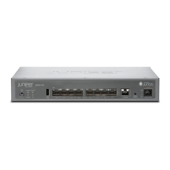
SRX110 Services Gateway Front Panel
SRX110 Services Gateway (SRX110H-VA) Front Panel
1
2
3
SRX110 Services Gateway (SRX110H-VB) Front Panel
1
2
3
Callout
Description
Callout
1
Power button
5
2
LEDs: Alarm, Status,
6
Power, and 3G
3
Universal serial bus (USB)
7
port
4
Fast Ethernet ports
8
4
5
6
7
8
4
5
6
7
8
Description
Console port
Reset Config button
LEDs: SYNC and TX/RX
For SRX110H-VA—VDSL/ADSL-POTS
For SRX110H-VB—VDSL/ADSL-ISDN
SRX110 Services Gateway Back Panel
SRX110 Services Gateway (SRX110H-VA and SRX110H-VB) Back Panel
1
2
3
4
Callout Description
1
Cable tie holder
2
3G-WAN (USB port)
3
Lock
4
Grounding point
NOTE: If you experience a problem with the CompactFlash card, you must return the
services gateway for repair or replacement. To do this, contact Juniper Networks
Technical Assistance Center (JTAC).
SRX110 Services Gateway Models
The following models of SRX110 Services Gateways are available:
Device
SRX110H-VA (VDSL/ADSL-POTS)
SRX110H-VB (VDSL/ADSL-ISDN)
Connecting and Configuring the SRX Series Device
Following are the tasks for connecting and configuring the SRX110 Services Gateway.
The LEDs on the front of the device indicate the status of the device.
The services gateway requires these basic configuration settings to function properly:
All interfaces must be assigned IP addresses, bound to zones, and configured as
Layer 3 interfaces.
Policies must be configured between zones to permit or deny traffic.
Source NAT rules must be set.
5
6
7
Callout
Description
5
CompactFlash card
6
Power supply point
7
Cable tie holder
DDR Memory
1 GB
1 GB
Advertisement
Table of Contents

Subscribe to Our Youtube Channel
Related Manuals for Juniper SRX110


Summary of Contents for Juniper SRX110
- Page 1 SRX110 Services Gateway Quick Start SRX110 Services Gateway Back Panel The instructions in this guide help you connect the SRX110 Services Gateway to your network. For details, see the SRX110 Services Gateway Hardware Guide at http://www.juniper.net/techpubs/a063.html. SRX110 Services Gateway (SRX110H-VA and SRX110H-VB) Back Panel...
- Page 2 Connect an Ethernet cable from any one port between the ports labeled 0/1 and 0/7 When an SRX110 Services Gateway is powered on for the first time, it boots using (interfaces fe-0/0/1 through fe-0/0/7) on the front panel to the Ethernet port on the ...
- Page 3 To configure the VDSL2 port to acquire an IP address, see Connecting and Configuring pt-1/0/0, and click Edit. the SRX110 Services Gateway Supported Interfaces. On the Add/Edit interface page, next to Address, clear DHCP and select IP Task 5: Access the J-Web Interface Address.
- Page 4 Connecting and Configuring the SRX110 Services Gateway Task 2: Connect and Configure the 3G USB Modem Supported Interfaces To connect and configure the SRX110 Services Gateway 3G USB modem, see Overview SRX110 Services Gateway Hardware Guide at http://www.juniper.net/techpubs/a063.html The integrated VDSL2 interface carries the Ethernet backplane.
- Page 5 For more information about using the Reset Config button, including how to change its Contacting Juniper Networks default behavior, see the hardware guide for your device. For technical support, see www.juniper.net/support/requesting-support.html. Page...
- Page 6 Juniper Networks, Inc. All other trademarks, service marks, registered trademarks, or registered service marks are the property of their respective owners. Juniper Networks assumes no responsibility for any inaccuracies in this document. Juniper Networks reserves the right to change, modify, transfer, or otherwise revise this publication without notice. Products made or sold by Juniper Networks or components thereof might be covered by one or more of the following patents that are owned by or licensed to Juniper Networks: U.S.
Need help?
Do you have a question about the SRX110 and is the answer not in the manual?
Questions and answers