
Subscribe to Our Youtube Channel
Related Manuals for Juniper SRX110 H2


Summary of Contents for Juniper SRX110 H2
- Page 1 SRX110 Services Gateway Hardware Guide for H2 Model Numbers Modified: 2015-06-17 Copyright © 2015, Juniper Networks, Inc.
- Page 2 END USER LICENSE AGREEMENT The Juniper Networks product that is the subject of this technical documentation consists of (or is intended for use with) Juniper Networks software. Use of such software is subject to the terms and conditions of the End User License Agreement (“EULA”) posted at http://www.juniper.net/support/eula.html.
-
Page 3: Table Of Contents
SRX110 Services Gateway Ethernet Port LEDs ......21 SRX110 Services Gateway Integrated VDSL2 Interface LEDs ....22 Copyright © 2015, Juniper Networks, Inc. - Page 4 Installing the SRX110 Services Gateway on a Desk ......63 Copyright © 2015, Juniper Networks, Inc.
- Page 5 Monitoring the SRX110 Services Gateway Components Using LEDs ..110 Monitoring the SRX110 Services Gateway Using Chassis Alarm Conditions ..112 Copyright © 2015, Juniper Networks, Inc.
- Page 6 Changing the Reset Config Button Behavior on the SRX110 Services Gateway . . 116 Juniper Networks Technical Assistance Center ......117...
- Page 7 Index ............163 Copyright © 2015, Juniper Networks, Inc.
- Page 8 SRX110 Services Gateway Hardware Guide for H2 Model Numbers viii Copyright © 2015, Juniper Networks, Inc.
-
Page 9: List Of Figures
Brackets ............65 Copyright © 2015, Juniper Networks, Inc. - Page 10 General Safety Guidelines and Warnings ......129 Figure 30: Placing a Component into an Electrostatic Bag ....134 Copyright © 2015, Juniper Networks, Inc.
- Page 11 Table 22: Cable and Wire Specifications for Ports ......41 Copyright © 2015, Juniper Networks, Inc.
- Page 12 Troubleshooting Components ........109 Copyright © 2015, Juniper Networks, Inc.
- Page 13 Contacting Customer Support and Returning Components ... . 121 Table 48: Return Procedure for SRX110 Services Gateway ....122 Copyright © 2015, Juniper Networks, Inc. xiii...
- Page 14 SRX110 Services Gateway Hardware Guide for H2 Model Numbers Copyright © 2015, Juniper Networks, Inc.
-
Page 15: About The Documentation
® To obtain the most current version of all Juniper Networks technical documentation, see the product documentation page on the Juniper Networks website at http://www.juniper.net/techpubs/ If the information in the latest release notes differs from the information in the documentation, follow the product Release Notes. -
Page 16: Table 1: Notice Icons
RFC 1997, BGP Communities Attribute Italic text like this Represents variables (options for which Configure the machine’s domain name: you substitute a value) in commands or [edit] configuration statements. root@# set system domain-name domain-name Copyright © 2015, Juniper Networks, Inc. -
Page 17: Documentation Feedback
We encourage you to provide feedback, comments, and suggestions so that we can improve the documentation. You can provide feedback by using either of the following methods: Online feedback rating system—On any page at the Juniper Networks Technical Documentation site at , simply click the http://www.juniper.net/techpubs/index.html... -
Page 18: Requesting Technical Support
7 days a week, 365 days a year. Self-Help Online Tools and Resources For quick and easy problem resolution, Juniper Networks has designed an online self-service portal called the Customer Support Center (CSC) that provides you with the following features: Find CSC offerings: http://www.juniper.net/customers/support/... - Page 19 About the Documentation For international or direct-dial options in countries without toll-free numbers, see http://www.juniper.net/support/requesting-support.html Copyright © 2015, Juniper Networks, Inc.
- Page 20 SRX110 Services Gateway Hardware Guide for H2 Model Numbers Copyright © 2015, Juniper Networks, Inc.
-
Page 21: Overview
PART 1 Overview System Overview on page 3 Hardware Component Overview on page 9 Chassis Description on page 15 Copyright © 2015, Juniper Networks, Inc. - Page 22 SRX110 Services Gateway Hardware Guide for H2 Model Numbers Copyright © 2015, Juniper Networks, Inc.
-
Page 23: System Overview
Accessing the SRX110 Services Gateway on page 4 About the SRX110 Services Gateway The Juniper Networks SRX110 Services Gateway offers complete functionality and flexibility for delivering secure and reliable data along with multiple integrated interfaces that support WAN and LAN connectivity. The SRX110 Services Gateway supports interfaces such as 3G USB modem and integrated very-high-bit-rate digital subscriber line version 2 (VDSL2). -
Page 24: Srx110 Services Gateway Models
SRX110 Services Gateway models with 2 GB memory. For information on the models with 1 GB memory, see SRX110 Services Gateway Hardware Guide for H Model Numbers. Copyright © 2015, Juniper Networks, Inc. -
Page 25: Table 4: Srx110 Services Gateway Hardware Features
If there is any problem with the CompactFlash card, you must return the services gateway for repair or replacement. For this, you need to contact Juniper Networks Technical Assistance Center (JTAC). For more details on Junos OS features and licenses for the SRX110 Services Gateway,... -
Page 26: Srx110 Services Gateway Integrated Vdsl2 Interface Overview
Asynchronous Transfer Mode (ATM) quality of service (QoS) (supported only when the VDSL2 interface is operating in ADSL2 mode) Multilink Point-to-Point Protocol (MLPPP) (supported only when the VDSL2 interface is operating in ADSL2 mode) Copyright © 2015, Juniper Networks, Inc. -
Page 27: Srx110 Services Gateway Integrated Vdsl2 Interface Supported Profiles
SRX110 Services Gateway Integrated VDSL2 Interface Overview on page 6 Documentation SRX110 Services Gateway Integrated VDSL2 Interface LEDs on page 22 Configuring the Integrated VDSL2 Interface on the SRX110 Services Gateway on page 103 Copyright © 2015, Juniper Networks, Inc. - Page 28 SRX110 Services Gateway Hardware Guide for H2 Model Numbers Copyright © 2015, Juniper Networks, Inc.
-
Page 29: Hardware Component Overview
SRX110 Services Gateway Power Supply The power supply for the SRX110 Services Gateway is external. You must use the power supply adapter provided by Juniper Networks to provide power to the services gateway. Figure 1 on page 9 shows the label for the 12 V power supply. -
Page 30: Srx110 Services Gateway 3G Usb Modem Overview
3G USB modem as a backup interface, you can use the dialer feature available in the services gateway. The 3G USB modem is secured with a USB protection cover as shown Figure 2 on page Copyright © 2015, Juniper Networks, Inc. -
Page 31: Figure 2: 3G Usb Modem With Usb Protection Cover
Installing a 3G USB Modem in the SRX110 Services Gateway USB Port on page 67 Documentation SRX110 Services Gateway 3G-WAN USB Port Physical Specifications on page 32 Configuring the 3G USB Modem on the SRX110 Services Gateway on page 102 Copyright © 2015, Juniper Networks, Inc. -
Page 32: Srx110 Services Gateway 3G Usb Modem Key Features
The 3G USB modem does not support the dial-in feature. Card information availability—You can use CLI commands to obtain information about a 3G USB modem, such as type, version, wireless status, and user profiles. Copyright © 2015, Juniper Networks, Inc. - Page 33 SRX110 Services Gateway 3G USB Modem Overview on page 10 Documentation Installing a 3G USB Modem in the SRX110 Services Gateway USB Port on page 67 SRX110 Services Gateway 3G-WAN USB Port Physical Specifications on page 32 Copyright © 2015, Juniper Networks, Inc.
- Page 34 SRX110 Services Gateway Hardware Guide for H2 Model Numbers Copyright © 2015, Juniper Networks, Inc.
-
Page 35: Chassis Description
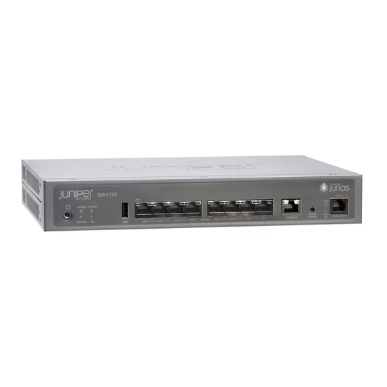
SRX110 Services Gateway Front Panel View with 3G and Integrated VDSL2 Figure 3 on page 15 Figure 4 on page 16 show the front panels of the SRX110 Services Gateway models SRX110H2-VA and SRX110H2-VB. Figure 3: SRX110 Services Gateway Front Panel (SRX110H2-VA) Copyright © 2015, Juniper Networks, Inc. -
Page 36: Srx110 Services Gateway Back Panel View
SRX110 Services Gateway Boot Devices and Dual-Root Partitioning Scheme on page 22 SRX110 Services Gateway Back Panel View Figure 5 on page 16 shows the back panel of the SRX110 Services Gateway. Figure 5: SRX110 Services Gateway Back Panel Copyright © 2015, Juniper Networks, Inc. -
Page 37: Srx110 Services Gateway Built-In Interfaces
If there is any problem with the CompactFlash card, you must return the services gateway for repair or replacement. For this, you need to contact Juniper Networks Technical Assistance Center (JTAC). The cable tie holder provides support for holding the power cord to the power supply point. -
Page 38: Table 10: Srx110 Services Gateway Built-In Hardware Interfaces
To provide the console interface. Uses an RJ-45 serial cable connector To function as a management port for Supports the RS-232 logging in to a device (EIA-232) standard directly. To configure the device using the CLI. Copyright © 2015, Juniper Networks, Inc. -
Page 39: Srx110 Services Gateway Leds
Figure 6 on page 19 shows the SRX110 Services Gateway Front Panel LEDs. Figure 6: SRX110 Services Gateway Front Panel LEDs Table 11 on page 20 lists the LED indicators on the SRX110 Services Gateway front panel. Copyright © 2015, Juniper Networks, Inc. -
Page 40: Table 11: Srx110 Services Gateway Front Panel Components Leds
Solid amber indicates that the 3G USB modem plugging in the modem. is registered with network. Off indicates that the 3G USB modem is not detected. Copyright © 2015, Juniper Networks, Inc. -
Page 41: Srx110 Services Gateway Ethernet Port Leds
On, not Link is active. No data blinking communication is taking place. Link is inactive. NOTE: The LED marked as 2 in Figure 7 on page 21 is not functional in this release. Copyright © 2015, Juniper Networks, Inc. -
Page 42: Srx110 Services Gateway Integrated Vdsl2 Interface Leds
This topic includes the following sections: Boot Devices on page 22 Dual-Root Partitioning Scheme on page 23 Boot Devices The SRX110 Services Gateway can boot from two devices: CompactFlash (default; always present) USB storage key (alternate) Copyright © 2015, Juniper Networks, Inc. -
Page 43: Dual-Root Partitioning Scheme
SRX110 Services Gateway Front Panel and Back Panel Views with 3G and Integrated Documentation VDSL2 on page 15 SRX110 Services Gateway LEDs on page 19 SRX110 Services Gateway Power Supply on page 9 SRX110 Services Gateway Specifications on page 30 Copyright © 2015, Juniper Networks, Inc. - Page 44 SRX110 Services Gateway Hardware Guide for H2 Model Numbers Copyright © 2015, Juniper Networks, Inc.
-
Page 45: Site Planning And Specifications
PART 2 Site Planning and Specifications Planning and Preparing the Site on page 27 Power Requirements and Specifications on page 37 Cable Specifications and Pinouts on page 41 Copyright © 2015, Juniper Networks, Inc. - Page 46 SRX110 Services Gateway Hardware Guide for H2 Model Numbers Copyright © 2015, Juniper Networks, Inc.
-
Page 47: Planning And Preparing The Site
Table 14: Site Preparation Checklist for Services Gateway Installation Additional Item or Task Information Performed By Date Notes Environment Verify that the “SRX110 environmental factors Services such as temperature Gateway and humidity do not Specifications” exceed device on page 30 tolerances. Power Copyright © 2015, Juniper Networks, Inc. - Page 48 55 structure. Cabinet Requirements Verify that your “SRX110 cabinet meets the Services minimum Gateway requirements. Cabinet Requirements” Plan the cabinet on page 32 location, including the required space clearances. Wall Installation Copyright © 2015, Juniper Networks, Inc.
-
Page 49: Planning And Preparing The Site
General Site Guidelines for Installing the SRX110 Services Gateway on page 30 SRX110 Services Gateway Cabinet Requirements on page 32 SRX110 Services Gateway Rack Requirements on page 33 Clearance Requirements for Airflow and Hardware Maintenance of the SRX110 Services Gateway on page 34 Copyright © 2015, Juniper Networks, Inc. -
Page 50: General Site Guidelines For Installing The Srx110 Services Gateway
The SRX110 Services Gateway chassis is a rigid sheet metal structure of 1 rack unit (U) height, which houses all the other hardware components. Figure 8 on page 30 shows the SRX110 Services Gateway with 3G and VDSL2 (VDSL/ADSL-POTS). Figure 8: SRX110 Services Gateway with 3G and VDSL2 (VDSL/ADSL-POTS) Copyright © 2015, Juniper Networks, Inc. -
Page 51: Figure 9: Srx110 Services Gateway With 3G And Vdsl2 (Vdsl/Adsl-Isdn)
–40° F (–40° C) to 158° F (70° C) Maximum thermal output 99 BTU/hour Noise level < 15 dB(A) or less per EN ISO 7779 Related SRX110 Services Gateway Description on page 3 Documentation Copyright © 2015, Juniper Networks, Inc. -
Page 52: Srx110 Services Gateway 3G-Wan Usb Port Physical Specifications
Size 19 in. (48.3 cm) as defined in Cabinets, Racks, Panels, and Associated Equipment (document number EIA-310–D) published by the Electronics Industry Association http://www.eia.org You can mount the services gateway horizontally in the cabinet. Copyright © 2015, Juniper Networks, Inc. -
Page 53: Srx110 Services Gateway Rack Requirements
The services gateway cannot be center mounted in a rack. Table 18 on page 34 provides the details of requirements for rack size, clearance, airflow, spacing of mounting brackets and flange holes, and connecting to the building structure. Copyright © 2015, Juniper Networks, Inc. -
Page 54: Clearance Requirements For Airflow And Hardware Maintenance Of The Srx110 Services Gateway
For service personnel to remove and install hardware components, there must be adequate space at the front and back of the device. Allow at least 24 in. (61 cm) both in front of and behind the device. Copyright © 2015, Juniper Networks, Inc. -
Page 55: Table 19: Clearance Requirements For The Services Gateway
Related General Site Guidelines for Installing the SRX110 Services Gateway on page 30 Documentation SRX110 Services Gateway Cabinet Requirements on page 32 SRX110 Services Gateway Rack Requirements on page 33 Copyright © 2015, Juniper Networks, Inc. - Page 56 SRX110 Services Gateway Hardware Guide for H2 Model Numbers Copyright © 2015, Juniper Networks, Inc.
-
Page 57: Power Requirements And Specifications
The potential for damage from lightning strikes increases if wires exceed recommended distances or if wires pass between buildings. Shield all conductors. The electromagnetic pulse (EMP) caused by lightning can damage unshielded conductors and destroy electronic devices. Copyright © 2015, Juniper Networks, Inc. -
Page 58: Srx110 Services Gateway Electrical And Power Requirements
Grounding guidelines and specifications for the device Related SRX110 Services Gateway Site Electrical Wiring Guidelines on page 37 Documentation Clearance Requirements for Airflow and Hardware Maintenance of the SRX110 Services Gateway on page 34 Copyright © 2015, Juniper Networks, Inc. -
Page 59: Srx110 Services Gateway Power Specifications And Requirements
Related SRX110 Services Gateway Electrical Safety Guidelines and Warnings on page 155 Documentation SRX110 Services Gateway Power Supply on page 9 SRX110 Services Gateway Grounding Specifications on page 71 Copyright © 2015, Juniper Networks, Inc. - Page 60 SRX110 Services Gateway Hardware Guide for H2 Model Numbers Copyright © 2015, Juniper Networks, Inc.
-
Page 61: Cable Specifications And Pinouts
RJ-45 Connector Pinouts for the SRX110 Services Gateway Ethernet Port on page 42 Documentation RJ-45 Connector Pinouts for the SRX110 Services Gateway Console Port on page 43 RJ-11 Connector Pinouts for the SRX110 Services Gateway on page 44 Copyright © 2015, Juniper Networks, Inc. -
Page 62: Rj-45 Connector Pinouts For The Srx110 Services Gateway Ethernet Port
Table 24 on page 42 describes the RJ-45 connector pinouts for the Ethernet port for 1 Gbps (1000 Mbps). Table 24: RJ-45 Connector Pinouts for the Services Gateway Ethernet Port (1 Gbps) Signal BI_DA+ BI_DA- BI_DB+ BI_DC+ BI_DC- Copyright © 2015, Juniper Networks, Inc. -
Page 63: Rj-45 Connector Pinouts For The Srx110 Services Gateway Console Port
Table 25: RJ-45 Connector Pinouts for the Services Gateway Console Port Signal Description Request to Send Data Terminal Ready Transmit Data Ground Signal Ground Ground Signal Ground Receive Data DSR/DCD Data Set Ready Clear to Send Copyright © 2015, Juniper Networks, Inc. -
Page 64: Connector Pinouts For The Srx110 Services Gateway
RJ N –Tip No connect No connect Related Connecting and Organizing the SRX110 Services Gateway Interface Cables on page 75 Documentation Interface Cable and Wire Specifications for the SRX110 Services Gateway on page 41 Copyright © 2015, Juniper Networks, Inc. -
Page 65: Initial Installation And Configuration
Grounding the SRX110 Services Gateway on page 71 Connecting the SRX110 Services Gateway to External Devices on page 75 Providing Power to the SRX110 Services Gateway on page 79 Performing Initial Configuration on page 83 Copyright © 2015, Juniper Networks, Inc. - Page 66 SRX110 Services Gateway Hardware Guide for H2 Model Numbers Copyright © 2015, Juniper Networks, Inc.
-
Page 67: Installation Overview
Install the services gateway. “Installing the SRX110 Services Gateway in a Rack” on page 59 “Installing the SRX110 Services Gateway on a Desk” on page 63 “Installing the SRX110 Services Gateway on a Wall” on page 65 Copyright © 2015, Juniper Networks, Inc. -
Page 68: Gateway
“Connecting the SRX110 Services SRX110 Services grounding wrist strap Gateway to the Power Supply” on Gateway page 79 Grounding the SRX110 Phillips (+) screwdriver, “Grounding the SRX110 Services Services Gateway number 1 Gateway” on page 72 Copyright © 2015, Juniper Networks, Inc. -
Page 69: Srx110 Services Gateway Autoinstallation Overview
For more information about configuring autoinstallation, see the following topics: Initial Configuration for Security Devices Monitoring and Troubleshooting for Security Devices Related Connecting the SRX110 Services Gateway to the Power Supply on page 79 Documentation Grounding the SRX110 Services Gateway on page 72 Copyright © 2015, Juniper Networks, Inc. - Page 70 SRX110 Services Gateway Hardware Guide for H2 Model Numbers Powering On the SRX110 Services Gateway on page 80 Powering Off the SRX110 Services Gateway on page 81 SRX110 Services Gateway Software Configuration Overview on page 83 Copyright © 2015, Juniper Networks, Inc.
-
Page 71: Unpacking The Services Gateway
Check the parts in the shipment against the items on the packing list. The packing list specifies the part numbers and descriptions of each part in your order. If any part is missing, contact your Juniper Networks customer service representative. Copyright © 2015, Juniper Networks, Inc. -
Page 72: Table 29: Parts List For A Fully Configured Srx110 Services Gateway
Product Registration NOTE: The mounting kits available for rack, wall, and desk installation of the SRX110 Services Gateway must be ordered separately. Contact your Juniper Networks customer service representative for more information. Related Required Tools and Parts for Installing and Maintaining the SRX110 Services Gateway... - Page 73 Chapter 8: Unpacking the Services Gateway Preparing the SRX110 Services Gateway for Rack-Mount, Desk-Mount, and Wall-Mount Installation Copyright © 2015, Juniper Networks, Inc.
- Page 74 SRX110 Services Gateway Hardware Guide for H2 Model Numbers Copyright © 2015, Juniper Networks, Inc.
-
Page 75: Installing The Mounting Hardware
Hardware Maintenance of the SRX110 maintenance, and secure it to the building structure. Services Gateway” on page 34 Remove the services gateway chassis from the “Unpacking the SRX110 Services Gateway” shipping carton. on page 51 Copyright © 2015, Juniper Networks, Inc. -
Page 76: Preparing The Srx110 Services Gateway For Desk-Mount Installation
Place the desk in its permanent location, allowing “Clearance Requirements for Airflow and adequate clearance for airflow and maintenance, and Hardware Maintenance of the SRX110 secure it to the building structure. Services Gateway” on page 34 Copyright © 2015, Juniper Networks, Inc. -
Page 77: Preparing The Srx110 Services Gateway For Wall-Mount Installation
Additional Information Verify that the site meets the requirements. Site Preparation Checklist for the SRX110 Services Gateway Remove the services gateway chassis from the shipping “Unpacking the SRX110 Services carton. Gateway” on page 51 Copyright © 2015, Juniper Networks, Inc. - Page 78 Clearance Requirements for Airflow and Hardware Maintenance of the SRX110 Services Gateway on page 34 Preparing the SRX110 Services Gateway for Rack-Mount Installation on page 55 Preparing the SRX110 Services Gateway for Desk-Mount Installation on page 56 Copyright © 2015, Juniper Networks, Inc.
-
Page 79: Installing The Services Gateway
If you are installing multiple devices in one rack, install the first device in the lowest position in the rack and proceed upward in the rack. Ensure that the rubber feet on the base of the chassis are removed for rack installation. Copyright © 2015, Juniper Networks, Inc. -
Page 80: Figure 12: Srx110 Services Gateway Installation In A Rack - Positioning Mounting
Use a Phillips (+) screwdriver, number 1, to install the screws that secure the mounting brackets and power supply adapter tray to the chassis as shown in Figure 13 on page Figure 13: SRX110 Services Gateway Rack Installation — Securing Mounting Brackets and Power Supply Adapter Tray Copyright © 2015, Juniper Networks, Inc. -
Page 81: Figure 14: Srx110 Services Gateway Rack Installation - Positioning Power Supply
Figure 15: SRX110 Services Gateway Rack Installation — Hanging the Services Gateway in a Rack Have a second person install a mounting screw into each of the two aligned holes. Use a Phillips (+) screwdriver, number 3, to tighten the screws. Copyright © 2015, Juniper Networks, Inc. -
Page 82: Adjusting The Power Supply Adapter Tray For The Srx110 Services Gateway For Rack-Mount Installation
Figure 16 on page 62 shows the adjustments to the power supply adapter tray required for the 60-watt power supply. Figure 16: Adjusting the Power Supply Adapter Tray to Accommodate the 60-Watt Power Supply Copyright © 2015, Juniper Networks, Inc. -
Page 83: Installing The Srx110 Services Gateway On A Desk
Make sure that the rubber feet are attached to the chassis. Place the device on a desk with the Juniper Networks logo facing up. The logo is embossed on the top cover. To install the device in a vertical position: Place the device on a flat and level surface, with the Juniper Networks logo facing up. -
Page 84: Figure 17: Srx110 Services Gateway Desk Installation - Attaching The Vertical
Figure 18: SRX110 Services Gateway Desk Installation — Placing the Services Gateway on a Desk Related SRX110 Services Gateway Installation Safety Guidelines and Warnings on page 139 Documentation Required Tools and Parts for Installing and Maintaining the SRX110 Services Gateway on page 48 Copyright © 2015, Juniper Networks, Inc. -
Page 85: Installing The Srx110 Services Gateway On A Wall
To install the device on a wall: Place the device on a flat, level surface, with the Juniper Networks logo facing up. The logo is embossed on the top cover. Ensure that the rubber feet are attached to the bottom of the chassis. -
Page 86: Figure 20: Srx110 Services Gateway Wall Installation - Attaching The Mounting
Adjusting the Power Supply Adapter Tray for the SRX110 Services Gateway for Rack-Mount Installation on page 62 Installing the SRX110 Services Gateway in a Rack on page 59 Installing the SRX110 Services Gateway on a Desk on page 63 Copyright © 2015, Juniper Networks, Inc. -
Page 87: Installing A 3G Usb Modem In The Srx110 Services Gateway Usb Port
Table 36 on page 67 lists the components of the 3G USB modem with USB protection cover. Table 36: 3G USB Modem with USB Protection Cover Components Number Component USB mount top cover USB modem USB mount (magnetic/non-magnetic) Copyright © 2015, Juniper Networks, Inc. -
Page 88: Installing A 3G Usb Modem On The Rear Side Of The Srx110 Services Gateway
On the rear side of the device, insert the USB modem extension cable into the 3G-WAN USB port until the cable is engaged (see Figure 22 on page 68). Figure 22: Connecting the 3G USB modem to the SRX110 Services Gateway Copyright © 2015, Juniper Networks, Inc. -
Page 89: Figure 23: 3G Usb Modem Wall Installation-Attaching The Usb Protection
USB protection cover using screw holes as shown in Figure 24 on page Figure 23: 3G USB Modem Wall Installation—Attaching the USB Protection Cover Figure 24: 3G USB Modem Ceiling Installation—Attaching the USB Protection Cover Copyright © 2015, Juniper Networks, Inc. - Page 90 SRX110 Services Gateway 3G USB Modem Overview on page 10 Documentation SRX110 Services Gateway 3G-WAN USB Port Physical Specifications on page 32 Configuring the 3G USB Modem on the SRX110 Services Gateway on page 102 Copyright © 2015, Juniper Networks, Inc.
-
Page 91: Grounding The Srx110 Services Gateway
SRX110 Services Gateway Site Electrical Wiring Guidelines on page 37 Documentation SRX110 Services Gateway Power Specifications and Requirements on page 39 Interface Cable and Wire Specifications for the SRX110 Services Gateway on page 41 Copyright © 2015, Juniper Networks, Inc. -
Page 92: Grounding The Srx110 Services Gateway
Before device installation begins, a licensed electrician must attach a cable lug to the grounding and power cables that you use. A cable with an incorrectly attached lug can damage the device (for example, by causing a short circuit). Copyright © 2015, Juniper Networks, Inc. - Page 93 SRX110 Services Gateway Grounding Specifications on page 71 Powering On the SRX110 Services Gateway on page 80 Powering Off the SRX110 Services Gateway on page 81 SRX110 Services Gateway General Safety Guidelines and Warnings on page 131 Copyright © 2015, Juniper Networks, Inc.
- Page 94 SRX110 Services Gateway Hardware Guide for H2 Model Numbers Copyright © 2015, Juniper Networks, Inc.
-
Page 95: Connecting The Srx110 Services Gateway To External Devices
Documentation Grounding the SRX110 Services Gateway on page 72 Interface Cable and Wire Specifications for the SRX110 Services Gateway on page 41 General Site Guidelines for Installing the SRX110 Services Gateway on page 30 Copyright © 2015, Juniper Networks, Inc. -
Page 96: Connecting The Modem At The Srx110 Services Gateway End
Configure the modem to answer a call on the first ring by entering ATS0=1 Configure the modem to accept modem control DTR signals by entering AT&D1 Disable flow control by entering AT&K0 Save modem settings by entering AT&W Copyright © 2015, Juniper Networks, Inc. -
Page 97: Connecting The Modem To The Console Port On The Srx110 Services Gateway
Connect a modem at your remote location to a management device such as a PC or laptop computer. Start your asynchronous terminal emulation application (such as Microsoft Windows HyperTerminal) on the PC or laptop computer. Copyright © 2015, Juniper Networks, Inc. -
Page 98: Table 40: Port Settings For Connecting To The Cli At User End
Connecting the Modem at the SRX110 Services Gateway End on page 76 Documentation Connecting the Modem to the Console Port on the SRX110 Services Gateway on page 77 SRX110 Services Gateway Software Configuration Overview on page 83 Copyright © 2015, Juniper Networks, Inc. -
Page 99: Providing Power To The Srx110 Services Gateway
Plug the DC connector end of the power cable into the power connector on the back of the device (see Figure 26 on page 80). Plug the AC adapter end of the power cable into an AC power outlet. Copyright © 2015, Juniper Networks, Inc. -
Page 100: Powering On The Srx110 Services Gateway
SRX110 Services Gateway General Safety Guidelines and Warnings on page 131 Powering On the SRX110 Services Gateway To power on the services gateway: Ensure that you have connected the power supply to the device. Copyright © 2015, Juniper Networks, Inc. -
Page 101: Powering Off The Srx110 Services Gateway
Use the graceful shutdown method to halt, power off, or reboot the services gateway. Use the forced shutdown method as a last resort to recover the services gateway if the services gateway operating system is not responding to the graceful shutdown method. Copyright © 2015, Juniper Networks, Inc. - Page 102 Grounding the SRX110 Services Gateway on page 72 Using the Reset Config Button on the SRX110 Services Gateway on page 115 SRX110 Services Gateway Front Panel and Back Panel Views with 3G and Integrated VDSL2 SRX110 Services Gateway LEDs Copyright © 2015, Juniper Networks, Inc.
-
Page 103: Performing Initial Configuration
Table 41 on page 83 provides information on the storage media available on the services gateway. Table 41: Storage Media on the Services Gateway Storage Media Type CompactFlash Default; always present USB storage device Alternate Copyright © 2015, Juniper Networks, Inc. -
Page 104: Understanding Built-In Ethernet Ports
192.168.1.1/24 network. fe-0/0/1 fe-0/0/7 Any DHCP client host, for example, a PC or laptop computer, directly connected to any ports receives an address on the 192.168.1.1/24 network. fe-0/0/1 fe-0/0/7 Copyright © 2015, Juniper Networks, Inc. -
Page 105: Understanding Management Access
Connecting the Services Gateway to the CLI Locally on page 88 Connecting the SRX110 Services Gateway to the CLI Remotely Performing Initial Software Configuration on the SRX110 Services Gateway Using the CLI on page 96 Copyright © 2015, Juniper Networks, Inc. -
Page 106: Connecting The Srx110 Services Gateway To The J-Web Interface
Connect the other end of the Ethernet cable to any of the built-in Ethernet ports through on the services gateway. fe-0/0/1 fe-0/0/7 Wait until the Status LED on the front panel of the services gateway turns solid green. Copyright © 2015, Juniper Networks, Inc. -
Page 107: Srx110 Services Gateway Secure Web Access Overview
J-Web. SSL uses public-private key technology that requires a paired private key and an authentication certificate for providing the SSL service. SSL encrypts communication between your device and the Web browser with a session key negotiated by the SSL server certificate. Copyright © 2015, Juniper Networks, Inc. -
Page 108: Connecting The Services Gateway To The Cli Locally
If you plan to use the command-line interface (CLI) to configure the SRX110 Services Gateway, you must connect through the Console port, as shown in Figure 28 on page Figure 28: Connecting to the Console Port on an SRX110 Services Gateway Copyright © 2015, Juniper Networks, Inc. -
Page 109: Table 42: Port Settings For Connecting To The Console Port
When the services gateway has finished starting up, a login prompt appears. Log in as the user . No password is required at initial connection, but you must root assign a root password before committing any configuration settings. Copyright © 2015, Juniper Networks, Inc. -
Page 110: Viewing Factory-Default Settings Of The Srx110 Services Gateway
Copyright © 2015, Juniper Networks, Inc. - Page 111 SRX240 Services Gateway. % vi srx240-poe-16xge-factory.conf The following sample output displays the factory-default configuration on an SRX240 Services Gateway: ## $Id: $ ## Copyright (c) 2009, Juniper Networks, Inc. ## All rights reserved. system { autoinstallation { delete-upon-commit; traceoptions { level verbose;...
- Page 112 0 { family ethernet-switching { vlan { members vlan-trust; ge-0/0/3 { unit 0 { family ethernet-switching { vlan { members vlan-trust; ge-0/0/4 { unit 0 { family ethernet-switching { vlan { members vlan-trust; Copyright © 2015, Juniper Networks, Inc.
- Page 113 0 { family ethernet-switching { vlan { members vlan-trust; ge-0/0/9 { unit 0 { family ethernet-switching { vlan { members vlan-trust; ge-0/0/10 { unit 0 { family ethernet-switching { vlan { members vlan-trust; Copyright © 2015, Juniper Networks, Inc.
- Page 114 0 { family ethernet-switching { vlan { members vlan-trust; ge-0/0/15 { unit 0 { family ethernet-switching { vlan { members vlan-trust; vlan { unit 0 { family inet { address 192.168.1.1/24; poe { Copyright © 2015, Juniper Networks, Inc.
- Page 115 200; source-threshold 1024; destination-threshold 2048; timeout 20; land; zones { security-zone trust { host-inbound-traffic { system-services { all; protocols { all; interfaces { vlan.0; security-zone untrust { interfaces { ge-0/0/0.0 { host-inbound-traffic { Copyright © 2015, Juniper Networks, Inc.
-
Page 116: Performing Initial Software Configuration On The Srx110 Services Gateway Using
For complete information about enabling the device to forward traffic, including examples, see the appropriate Junos OS configuration guides. To configure the Junos OS: Verify that the device is powered on. Log in as the root user. There is no password. Copyright © 2015, Juniper Networks, Inc. - Page 117 0 family inet address address/prefix-length Configure the default route. [edit] admin@# set routing-options static route 0.0.0.0/0 next-hop gateway Configure basic security zones and bind them to traffic interfaces. [edit] admin@# set security zones security-zone untrust interfaces fe-0/0/1 Copyright © 2015, Juniper Networks, Inc.
- Page 118 [ lab.device.net device.net ]; backup-device 192.168.2.44; time-zone America/Los_Angeles; root-authentication { ssh-rsa "ssh-rsa AAAAB3Nza...D9Y2gXF9ac==root@devicea.lab.device.net"; name-server { 10.148.2.32; services { ntp { server 10.148.2.21; interfaces { fe-0/0/0 { unit 0 { family inet { address 192.168.1.1/24; Copyright © 2015, Juniper Networks, Inc.
-
Page 119: Performing Initial Software Configuration On The Srx110 Services Gateway Using The Setup Wizard
Provides recommended settings based on your previous selections. For example, the wizard recommends security policies based on the security topology you have defined. Determines which configuration tasks to present to you based on your selections. Copyright © 2015, Juniper Networks, Inc. -
Page 120: About The Default Setup Mode
Guided Setup mode, by using the J-Web interface, or by using the CLI. See the SRX110 Services Gateway Quick Start for step-by-step instructions on how to configure your services gateway in the Default Setup mode. Copyright © 2015, Juniper Networks, Inc. -
Page 121: About The Guided Setup Mode
The minimum screen resolution is 800 by 600 pixels. Enter the URL http://192.168.1.1 When the Welcome page for the setup wizard appears, choose the setup mode you want to use to configure your services gateway. Copyright © 2015, Juniper Networks, Inc. -
Page 122: Configuring The 3G Usb Modem On The Srx110 Services Gateway
Checks the status of the 3G USB modem. show modem wireless interface cl-0/0/8 show interfaces terse Unlocks the GSM SIM. request modem wireless gsm sim-unlock cl-0/0/8 Unlocks the SIM automatically on reboot. set interfaces cl-0/0/ 8 cellular-options gsm-options sim-unlock-code Copyright © 2015, Juniper Networks, Inc. -
Page 123: Configuring The Integrated Vdsl2 Interface On The Srx110 Services Gateway
Optionally, you can also assign the port an IP address (for example, 192.168.3.1/24). Enter or select the following settings: Select Configure>Security>Zones/Screens Add or select a security zone other than Null; for example, Trust For host inbound traffic, set the following: System Services= Allow All Copyright © 2015, Juniper Networks, Inc. - Page 124 Junos OS Interfaces Configuration Guide for Security Devices Related SRX110 Services Gateway Integrated VDSL2 Interface Overview on page 6 Documentation SRX110 Services Gateway Integrated VDSL2 Interface Key Features on page 6 SRX110 Services Gateway Integrated VDSL2 Interface LEDs on page 22 Copyright © 2015, Juniper Networks, Inc.
-
Page 125: Maintaining And Troubleshooting Components
PART 4 Maintaining and Troubleshooting Components Maintaining Components on page 107 Troubleshooting Components on page 109 Copyright © 2015, Juniper Networks, Inc. - Page 126 SRX110 Services Gateway Hardware Guide for H2 Model Numbers Copyright © 2015, Juniper Networks, Inc.
-
Page 127: Maintaining Components
We recommend using a surge protector for the power connection. Related Connecting the SRX110 Services Gateway to the Power Supply on page 79 Documentation Clearance Requirements for Airflow and Hardware Maintenance of the SRX110 Services Gateway on page 34 Copyright © 2015, Juniper Networks, Inc. - Page 128 SRX110 Services Gateway Hardware Guide for H2 Model Numbers Copyright © 2015, Juniper Networks, Inc.
-
Page 129: Troubleshooting Components
Using the Reset Config Button on the SRX110 Services Gateway on page 115 Changing the Reset Config Button Behavior on the SRX110 Services Gateway on page 116 Juniper Networks Technical Assistance Center on page 117 Monitoring the SRX110 Services Gateway Chassis Using the CLI You can monitor alarms to troubleshoot hardware problems on a services gateway. -
Page 130: Monitoring The Srx110 Services Gateway Components Using Leds
Monitoring the SRX110 Services Gateway Components Using LEDs You can monitor the chassis condition by using the LEDs. Table 45 on page 111 lists the LEDs, their condition, the possible causes and corrective actions. Copyright © 2015, Juniper Networks, Inc. -
Page 131: Table 45: Component Leds On The Services Gateway
The device is starting up. Normal condition. No action is required. NOTE: When the system is up and running, if the Alarm LED is off, it indicates that no alarms are present on the device. Copyright © 2015, Juniper Networks, Inc. -
Page 132: Monitoring The Srx110 Services Gateway Using Chassis Alarm Conditions
Initial Configuration for Security Devices Monitoring and Troubleshooting for Security Devices Table 46 on page 113 describes alarms that can occur for an SRX110 Services Gateway chassis component. Copyright © 2015, Juniper Networks, Inc. - Page 133 Using the Reset Config Button on the SRX110 Services Gateway on page 115 Changing the Reset Config Button Behavior on the SRX110 Services Gateway on page 116 Juniper Networks Technical Assistance Center on page 117 Copyright © 2015, Juniper Networks, Inc.
-
Page 134: Monitoring The Srx110 Services Gateway Power System
Using the Reset Config Button on the SRX110 Services Gateway on page 115 Changing the Reset Config Button Behavior on the SRX110 Services Gateway on page 116 Juniper Networks Technical Assistance Center on page 117 Resetting the SRX110 Services Gateway The Reset Config button on the front panel of the services gateway can be used to remove the current configuration and reset the device to the default (factory) configuration. -
Page 135: Using The Reset Config Button On The Srx110 Services Gateway
Status LED glows amber—deletes all configurations on the device, including the backup configurations and rescue configuration, and loads and commits the factory configuration. For details about factory-default settings, see the following topics: Initial Configuration for Security Devices Copyright © 2015, Juniper Networks, Inc. -
Page 136: Changing The Reset Config Button Behavior On The Srx110 Services Gateway
Monitoring the SRX110 Services Gateway Using Chassis Alarm Conditions on page 112 Monitoring the SRX110 Services Gateway Power System on page 114 Juniper Networks Technical Assistance Center on page 117 Changing the Reset Config Button Behavior on the SRX110 Services Gateway... -
Page 137: Juniper Networks Technical Assistance Center
If you need assistance while troubleshooting a services gateway, open a support case using the Case Manager link at , or call 1-888-314-JTAC http://www.juniper.net/support/ (within the United States) or 1-408-745-9500 (from outside the United States). Copyright © 2015, Juniper Networks, Inc. - Page 138 SRX110 Services Gateway Hardware Guide for H2 Model Numbers Copyright © 2015, Juniper Networks, Inc.
-
Page 139: Replacing Components
PART 5 Replacing Components Contacting Customer Support and Returning Components on page 121 Copyright © 2015, Juniper Networks, Inc. - Page 140 SRX110 Services Gateway Hardware Guide for H2 Model Numbers Copyright © 2015, Juniper Networks, Inc.
-
Page 141: Contacting Customer Support And Returning Components
Contacting Customer Support Once you have located the serial numbers of the services gateway or component, you can return them for repair or replacement. For this, you need to contact Juniper Networks Technical Assistance Center (JTAC). You can contact JTAC 24 hours a day, 7 days a week, using any of the following methods: On the Web: Using the Case Manager link at http://www.juniper.net/support/... -
Page 142: Return Procedure For The Srx110 Services Gateway
SRX110 Services Gateway Hardware Guide for H2 Model Numbers Information You Might Need to Supply to Juniper Networks Technical Assistance Center on page 124 Return Procedure for the SRX110 Services Gateway Follow the tasks list provided in Table 48 on page 122... -
Page 143: Cli
SRX110 Services Gateway Chassis Serial Number and Agency Labels on page 123 Listing the SRX110 Services Gateway and Component Details with the CLI Before contacting Juniper Networks to request an RMA, you must find the serial number on the SRX110 Services Gateway or component. -
Page 144: Center
Return Procedure for the SRX110 Services Gateway on page 122 Information You Might Need to Supply to Juniper Networks Technical Assistance Center If you are returning a services gateway or hardware component to Juniper Networks for repair or replacement, obtain a Return Materials Authorization (RMA) number from Juniper Networks Technical Assistance Center (JTAC). -
Page 145: Packing The Srx110 Services Gateway And Components For Shipment
To pack the services gateway for shipment: Retrieve the shipping carton and packing materials in which the device was originally shipped. If you do not have these materials, contact your Juniper Networks representative about approved packaging materials. Attach an electrostatic discharge (ESD) grounding strap to your bare wrist and connect the strap to the ESD point on the chassis or to an outside ESD point if the device is disconnected from earth ground. - Page 146 Locating the SRX110 Services Gateway Component Serial Number and Agency Labels on page 123 Return Procedure for the SRX110 Services Gateway on page 122 Information You Might Need to Supply to Juniper Networks Technical Assistance Center on page 124 Copyright © 2015, Juniper Networks, Inc.
-
Page 147: Safety And Regulatory Compliance Information
Laser and LED Safety Guidelines and Warnings on page 145 Maintenance and Operational Safety Guidelines and Warnings on page 149 Electrical Safety Guidelines and Warnings on page 155 Agency Approvals and Regulatory Compliance Information on page 157 Copyright © 2015, Juniper Networks, Inc. - Page 148 SRX110 Services Gateway Hardware Guide for H2 Model Numbers Copyright © 2015, Juniper Networks, Inc.
-
Page 149: General Safety Guidelines And Warnings
SRX110 Services Gateway General Safety Guidelines and Warnings on page 131 SRX110 Services Gateway Safety Requirements, Warnings, and Guidelines on page 135 SRX110 Services Gateway Definition of Safety Warning Levels This topic defines the following four levels of safety warnings used in Juniper Networks technical publications: NOTE: You might find this information helpful in a particular situation or might otherwise overlook it. - Page 150 Documentation SRX110 Services Gateway Fire Safety Requirements on page 137 SRX110 Services Gateway Installation Safety Guidelines and Warnings on page 139 SRX110 Services Gateway Laser and LED Safety Guidelines and Warnings on page 145 Copyright © 2015, Juniper Networks, Inc.
-
Page 151: Srx110 Services Gateway General Safety Guidelines And Warnings
Such an action could cause electrical shock. Qualified Personnel Warning WARNING: Only trained and qualified personnel should install or replace the services gateway. Waarschuwing Installatie en reparaties mogen uitsluitend door getraind en bevoegd personeel uitgevoerd worden. Copyright © 2015, Juniper Networks, Inc. - Page 152 Attention Cet appareil est à installer dans des zones d'accès réservé. Ces dernières sont des zones auxquelles seul le personnel de service peut accéder en utilisant un outil spécial, un mécanisme de verrouillage et une clé, ou tout Copyright © 2015, Juniper Networks, Inc.
- Page 153 Ett område med begränsat tillträde får endast tillträdas av servicepersonal med ett speciellt verktyg, lås och nyckel, eller annan säkerhetsanordning, och kontrolleras av den auktoritet som ansvarar för området. Preventing Electrostatic Discharge Damage to the Services Gateway Copyright © 2015, Juniper Networks, Inc.
-
Page 154: Figure 30: Placing A Component Into An Electrostatic Bag
Figure 30 on page 134. Figure 30: Placing a Component into an Electrostatic Bag Related SRX110 Services Gateway Definition of Safety Warning Levels on page 129 Documentation SRX110 Services Gateway Fire Safety Requirements on page 137 Copyright © 2015, Juniper Networks, Inc. -
Page 155: Srx110 Services Gateway Safety Requirements, Warnings, And Guidelines
General Site Guidelines for Installing the SRX110 Services Gateway on page 30 Documentation Required Tools and Parts for Installing and Maintaining the SRX110 Services Gateway on page 48 Preparing the SRX110 Services Gateway for Rack-Mount, Desk-Mount, and Wall-Mount Installation Copyright © 2015, Juniper Networks, Inc. - Page 156 SRX110 Services Gateway Hardware Guide for H2 Model Numbers Copyright © 2015, Juniper Networks, Inc.
-
Page 157: Fire Safety Requirements
In addition, establish procedures to protect your equipment in the event of a fire emergency. Juniper Networks products should be installed in an environment suitable for electronic equipment. We recommend that fire suppression equipment be available... - Page 158 To keep warranties effective, do not use a dry chemical fire extinguisher to control a fire at or near a Juniper Networks services gateway. If a dry chemical fire extinguisher is used, the unit is no longer eligible for coverage under a service agreement.
-
Page 159: Installation Safety Guidelines And Warnings
Aviso Leia as instruções de instalação antes de ligar o sistema à sua fonte de energia. ¡Atención! Ver las instrucciones de instalación antes de conectar el sistema a la red de alimentación. Varning! Läs installationsanvisningarna innan du kopplar systemet till dess strömförsörjningsenhet. Rack-Mounting Requirements and Warnings Copyright © 2015, Juniper Networks, Inc. - Page 160 De onderstaande richtlijnen worden verstrekt om uw veiligheid te verzekeren: De Juniper Networks services gateway moet in een stellage worden geïnstalleerd die aan een bouwsel is verankerd. Dit toestel dient onderaan in het rek gemonteerd te worden als het toestel het enige in het rek is.
- Page 161 Les directives ci-dessous sont destinées à assurer la protection du personnel: Le rack sur lequel est monté le Juniper Networks services gateway doit être fixé à la structure du bâtiment. Si cette unité constitue la seule unité montée en casier, elle doit être placée dans le bas.
- Page 162 Vær nøye med at systemet er stabilt. Følgende retningslinjer er gitt for å verne om sikkerheten: Juniper Networks services gateway må installeres i et stativ som er forankret til bygningsstrukturen. Denne enheten bør monteres nederst i kabinettet hvis dette er den eneste enheten i kabinettet.
- Page 163 Följande riktlinjer ges för att trygga din säkerhet: Juniper Networks services gateway måste installeras i en ställning som är förankrad i byggnadens struktur. Om denna enhet är den enda enheten på ställningen skall den installeras längst ned på...
- Page 164 SRX110 Services Gateway Hardware Guide for H2 Model Numbers Copyright © 2015, Juniper Networks, Inc.
-
Page 165: Laser And Led Safety Guidelines And Warnings
Class 1 Laser Product Warning WARNING: Class 1 laser product. Waarschuwing Klasse-1 laser produkt. Varoitus Luokan 1 lasertuote. Copyright © 2015, Juniper Networks, Inc. -
Page 166: Class 1 Led Product Warning
Waarschuwing Niet in de straal staren of hem rechtstreeks bekijken met optische instrumenten. Varoitus Älä katso säteeseen äläkä tarkastele sitä suoraan optisen laitteen avulla. Attention Ne pas fixer le faisceau des yeux, ni l'observer directement à l'aide d'instruments optiques. Copyright © 2015, Juniper Networks, Inc. -
Page 167: Radiation From Open Port Apertures Warning
åpning når det ikke er tilkoblet en fiberkabel. Aviso Dada a possibilidade de emissão de radiação invisível através do orifício da via de acesso, quando esta não tiver nenhum cabo de fibra conectado, Copyright © 2015, Juniper Networks, Inc. - Page 168 öppningar. Related SRX110 Services Gateway Installation Safety Guidelines and Warnings on page 139 Documentation SRX110 Services Gateway Maintenance and Operational Safety Guidelines and Warnings on page 149 Copyright © 2015, Juniper Networks, Inc.
-
Page 169: Maintenance And Operational Safety Guidelines And Warnings
Warnung Bei Einsetzen einer falschen Batterie besteht Explosionsgefahr. Ersetzen Sie die Batterie nur durch den gleichen oder vom Hersteller empfohlenen Batterietyp. Entsorgen Sie die benutzten Batterien nach den Anweisungen des Herstellers. Copyright © 2015, Juniper Networks, Inc. -
Page 170: Jewelry Removal Warning
à l'alimentation et reliés à la terre, les objets métalliques chauffent, ce qui peut provoquer des blessures graves ou souder l'objet métallique aux bornes. Warnung Vor der Arbeit an Geräten, die an das Netz angeschlossen sind, jeglichen Schmuck (einschließlich Ringe, Ketten und Uhren) abnehmen. Copyright © 2015, Juniper Networks, Inc. -
Page 171: Lightning Activity Warning
Attention Ne pas travailler sur le système ni brancher ou débrancher les câbles pendant un orage. Warnung Arbeiten Sie nicht am System und schließen Sie keine Kabel an bzw. trennen Sie keine ab, wenn es gewittert. Copyright © 2015, Juniper Networks, Inc. -
Page 172: Operating Temperature Warning
C). To prevent airflow restriction, allow at least 6 in. (15.2 cm) of clearance around the ventilation openings. Waarschuwing Om te voorkomen dat welke services gateway van de Juniper Networks services gateway dan ook oververhit raakt, dient u deze niet te bedienen op een plaats waar de maximale aanbevolen ο... -
Page 173: Product Disposal Warning
15,2 cm à volta das aberturas de ventilação. ¡Atención! Para impedir que un encaminador de la serie Juniper Networks services gateway se recaliente, no lo haga funcionar en un área en la que se ο... - Page 174 Varning! Slutlig kassering av denna produkt bör skötas i enlighet med landets alla lagar och föreskrifter. Related SRX110 Services Gateway Electrical Safety Guidelines and Warnings on page 155 Documentation SRX110 Services Gateway Laser and LED Safety Guidelines and Warnings on page 145 Copyright © 2015, Juniper Networks, Inc.
-
Page 175: Electrical Safety Guidelines And Warnings
Locate the emergency power-off switch for the room in which you are working so that if an electrical accident occurs, you can quickly turn off the power. Do not work alone if potentially hazardous conditions exist anywhere in your workspace. Copyright © 2015, Juniper Networks, Inc. - Page 176 SRX110 Services Gateway Power Specifications and Requirements on page 39 Documentation SRX110 Services Gateway Maintenance and Operational Safety Guidelines and Warnings on page 149 Grounding the SRX110 Services Gateway on page 72 SRX110 Services Gateway Agency Approvals on page 157 Copyright © 2015, Juniper Networks, Inc.
-
Page 177: Agency Approvals And Regulatory Compliance Information
AS/NZS CISPR 22 (2006) Class B FCC Part 15 Subpart B Class B (2009) USA Radiated Emissions Industry Canada ICES-003 Issue 4, February 7, 2004 Class B VCCI V-3 (2009.04) and V-4 (2009.04) Class B Japanese Radiated Emissions Copyright © 2015, Juniper Networks, Inc. -
Page 178: Srx110 Services Gateway Compliance Statements For Emc Requirements
United States on page 159 Canada This Class B digital apparatus complies with Canadian ICES-003. Cet appareil numérique de la classe B est conforme à la norme NMB-003 du Canada. European Community This is a Class B product. Copyright © 2015, Juniper Networks, Inc. -
Page 179: Japan
Increase the separation between the equipment and receiver. Connect the equipment into an outlet on a circuit different from that to which the receiver is connected. Consult the dealer or an experienced radio/TV technician for help. Copyright © 2015, Juniper Networks, Inc. -
Page 180: Srx110 Services Gateway Compliance Statements For Environmental Requirements
The maximum emitted sound pressure level is 70 dB(A) or less per EN ISO 7779. Related SRX110 Services Gateway Compliance Statements for Environmental Requirements Documentation on page 160 SRX110 Services Gateway Compliance Statements for EMC Requirements on page 158 SRX110 Services Gateway Agency Approvals on page 157 Copyright © 2015, Juniper Networks, Inc. -
Page 181: Index
PART 7 Index Index on page 163 Copyright © 2015, Juniper Networks, Inc. - Page 182 SRX110 Services Gateway Hardware Guide for H2 Model Numbers Copyright © 2015, Juniper Networks, Inc.
-
Page 183: Index
(chassis)............77, cable specifications............41 basic CLI command connecting through the CLI locally......88 3G USB modem............102 connecting through the CLI remotely....88 basic connectivity settings for local CLI connection......88 secure Web access............87 boot devices types..................22 Copyright © 2015, Juniper Networks, Inc. - Page 184 Ethernet port interfaces cable specifications............41 built-in..................17 RJ-45...................42 hardware................17 Internet..................3 factory-default configuration..........115 fire safety specifications.............137 Copyright © 2015, Juniper Networks, Inc.
- Page 185 Reset Config button commands...............116 set chassis commands..........116 parentheses, in syntax descriptions.......xvii using...................115 Copyright © 2015, Juniper Networks, Inc.
- Page 186 JTAC..........121 front panel.................15 support, technical See technical support grounding................72 supported profile hardware interfaces............17 VDSL2..................7 HTTPS Web access............87 SYNC LED................20, installation overview.............47 syntax conventions..............xvi installation process............47 LEDs..................19 monitoring component LEDs........110 technical support parts..................48 contacting JTAC............xviii Copyright © 2015, Juniper Networks, Inc.
- Page 187 Index temperature, acceptable range........30 thermal output................30 TX/RX LED.................20, modem................10 VDSL/ADSL-ISDN port............6 VDSL/ADSL-POTS port............6 VDSL2 configuring..............103 features.................6 LEDs..................22 supported profiles.............7 VDSL2 port..................6 wall installing................65 wall installation preparing................57 wall mount preparing................57 warnings electrical................155 wire specifications..............41 wireless..................10 Copyright © 2015, Juniper Networks, Inc.
- Page 188 SRX110 Services Gateway Hardware Guide for H2 Model Numbers Copyright © 2015, Juniper Networks, Inc.
Need help?
Do you have a question about the SRX110 H2 and is the answer not in the manual?
Questions and answers