Juniper SRX110 Hardware Manual
Hide thumbs
Also See for SRX110:
- Manual (180 pages) ,
- Quick start manual (6 pages) ,
- Hardware manual (188 pages)

Related Manuals for Juniper SRX110


Summary of Contents for Juniper SRX110
-
Page 1: Hardware Guide
SRX110 Services Gateway Hardware Guide Published: 2013-07-29 Copyright © 2013, Juniper Networks, Inc. - Page 2 Products made or sold by Juniper Networks or components thereof might be covered by one or more of the following patents that are owned by or licensed to Juniper Networks: U.S. Patent Nos. 5,473,599, 5,905,725, 5,909,440, 6,192,051, 6,333,650, 6,359,479, 6,406,312, 6,429,706, 6,459,579, 6,493,347, 6,538,518, 6,538,899, 6,552,918, 6,567,902, 6,578,186, and 6,590,785.
- Page 3 By downloading, installing or using such software, you agree to the terms and conditions of that EULA. Copyright © 2013, Juniper Networks, Inc.
- Page 4 Copyright © 2013, Juniper Networks, Inc.
-
Page 5: Table Of Contents
SRX110 Services Gateway Description ........3... - Page 6 Unpacking the SRX110 Services Gateway ......49 Unpacking the SRX110 Services Gateway ....... . 49 Verifying Parts Received with the SRX110 Services Gateway .
- Page 7 SRX110 Services Gateway Safety Requirements, Warnings, and Guidelines ..57 Installing the SRX110 Services Gateway ....... . . 57 Adjusting the Power Supply Adapter Tray for the SRX110 Services Gateway for Rack-Mount Installation .
- Page 8 General Electrical Safety Guidelines and Warnings ....126 SRX110 Services Gateway Agency Approvals ......127 SRX110 Services Gateway Compliance Statements for Environmental Requirements .
- Page 9 Hardware ............139 Return Procedure for the SRX110 Services Gateway ..... . . 139 Locating the SRX110 Services Gateway Component Serial Number and Agency Labels .
- Page 10 SRX110 Services Gateway Hardware Guide Copyright © 2013, Juniper Networks, Inc.
-
Page 11: About This Guide
This guide is designed for network administrators who are installing and maintaining a Juniper Networks SRX110 Services Gateway or preparing a site for device installation. To use this guide, you need a broad understanding of networks in general and the Internet in particular, networking principles, and network configuration. - Page 12 SRX110 Services Gateway Hardware Guide Table 1: Notice Icons Icon Meaning Description Informational note Indicates important features or instructions. Caution Indicates a situation that might result in loss of data or hardware damage. Warning Alerts you to the risk of personal injury or death.
-
Page 13: Srx Series Documentation And Release Notes
If the information in the latest SRX Series Release Notes differs from the information in the documentation, follow the SRX Series Release Notes. Obtaining Documentation To obtain the most current version of all Juniper Networks technical documentation, see the products documentation page on the Juniper Networks web site at http://www.juniper.net/techpubs... -
Page 14: Documentation Feedback
7 days a week, 365 days a year. Self-Help Online Tools and Resources For quick and easy problem resolution, Juniper Networks has designed an online self-service portal called the Customer Support Center (CSC) that provides you with the following features: Find CSC offerings: http://www.juniper.net/customers/support/... -
Page 15: Opening A Case With Jtac
About This Guide Join and participate in the Juniper Networks Community Forum: http://www.juniper.net/company/communities/ Open a case online in the CSC Case Management tool: http://www.juniper.net/cm/ To verify service entitlement by product serial number, use our Serial Number Entitlement (SNE) Tool: https://tools.juniper.net/SerialNumberEntitlementSearch/ Opening a Case with JTAC You can open a case with JTAC on the Web or by telephone. - Page 16 SRX110 Services Gateway Hardware Guide Copyright © 2013, Juniper Networks, Inc.
-
Page 17: Srx110 Services Gateway Overview
PART 1 SRX110 Services Gateway Overview Introduction to the SRX110 Services Gateway on page 3 SRX110 Services Gateway Hardware Components and Specifications on page 7 Copyright © 2013, Juniper Networks, Inc. - Page 18 SRX110 Services Gateway Hardware Guide Copyright © 2013, Juniper Networks, Inc.
-
Page 19: Introduction To The Srx110 Services Gateway
The Juniper Networks SRX110 Services Gateway offers complete functionality and flexibility for delivering secure and reliable data along with multiple integrated interfaces that support WAN and LAN connectivity. The SRX110 Services Gateway supports interfaces such as 3G USB modem and integrated very-high-bit-rate digital subscriber line version 2 (VDSL2). -
Page 20: Srx110 Services Gateway Models
On a single line, you type commands that are executed when you press the Enter key. The CLI provides command Help and command completion. For more details on the SRX110 Services Gateway software features and licenses, see the following guides:... - Page 21 For this, you need to contact Juniper Networks Technical Assistance Center (JTAC). For more details on Junos OS features and licenses for the SRX110 Services Gateway, see the following guides: Initial Configuration for Security Devices...
- Page 22 SRX110 Services Gateway Hardware Guide Copyright © 2013, Juniper Networks, Inc.
-
Page 23: Srx110 Services Gateway Hardware Components And Specifications
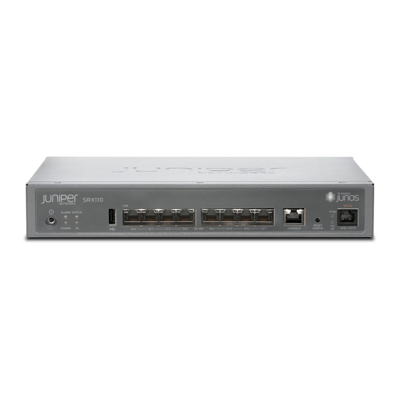
SRX110 Services Gateway Power Supply on page 16 SRX110 Services Gateway Specifications The SRX110 Services Gateway chassis is a rigid sheet metal structure of 1 rack unit (U) height, which houses all the other hardware components. Figure 1 on page 7 shows the SRX110 Services Gateway with 3G and VDSL2 (VDSL/ADSL-POTS). -
Page 24: Srx110 Services Gateway Specifications
Related SRX110 Services Gateway Description on page 3 Documentation SRX110 Services Gateway Front Panel and Back Panel Views with 3G and Integrated VDSL2 on page 9 Monitoring the SRX110 Services Gateway Components Using LEDs on page 98 Copyright © 2013, Juniper Networks, Inc. -
Page 25: Srx110 Services Gateway Front Panel And Back Panel Views
SRX110 Services Gateway Front Panel and Back Panel Views with 3G and Integrated VDSL2 on page 9 SRX110 Services Gateway Front Panel and Back Panel Views with 3G and Integrated VDSL2 This topic includes the following sections: SRX110 Services Gateway Front Panel View with 3G and Integrated VDSL2 on page 9... -
Page 26: Srx110 Services Gateway Back Panel View
For more information on the front panel components, see the following topics: SRX110 Services Gateway Built-In Interfaces on page 11 SRX110 Services Gateway LEDs on page 13 SRX110 Services Gateway Boot Devices and Dual-Root Partitioning Scheme on page 15 SRX110 Services Gateway Back Panel View Figure 5 on page 10 shows the back panel of the SRX110 Services Gateway. -
Page 27: Srx110 Services Gateway Built-In Interfaces
Chapter 2: SRX110 Services Gateway Hardware Components and Specifications Table 7: SRX110 Services Gateway Back Panel Components (continued) Number Component Cable tie holder NOTE: If there is any problem with the CompactFlash card, you must return the services gateway for repair or replacement. For this, you need to contact Juniper Networks Technical Assistance Center (JTAC). - Page 28 3G USB modem. Related SRX110 Services Gateway Specifications on page 7 Documentation SRX110 Services Gateway Front Panel and Back Panel Views with 3G and Integrated VDSL2 on page 9 Copyright © 2013, Juniper Networks, Inc.
-
Page 29: Srx110 Services Gateway Leds
SRX110 Services Gateway Front Panel LEDs. Figure 6: SRX110 Services Gateway Front Panel LEDs Table 9 on page 13 lists the LED indicators on the SRX110 Services Gateway front panel. Table 9: SRX110 Services Gateway Front Panel Components LEDs Component... -
Page 30: Srx110 Services Gateway Ethernet Port Leds
SRX110 Services Gateway Hardware Guide Table 9: SRX110 Services Gateway Front Panel Components LEDs (continued) Component Description Usage Power LED The Power LED has the following indicator colors: The Power LED can be used to determine if the device is Solid green indicates that the device is receiving power. -
Page 31: Srx110 Services Gateway Boot Devices And Dual-Root Partitioning Scheme
Related SRX110 Services Gateway Specifications on page 7 Documentation SRX110 Services Gateway Front Panel and Back Panel Views with 3G and Integrated VDSL2 on page 9 SRX110 Services Gateway Boot Devices and Dual-Root Partitioning Scheme on page 15 SRX110 Services Gateway Boot Devices and Dual-Root Partitioning Scheme... -
Page 32: Srx110 Services Gateway Power Supply
Junos OS image in the other root partition and remain fully functional. When the SRX110 Services Gateway powers up, it tries to boot Junos OS from the default storage medium. If the device fails to boot from the default storage medium, it tries to boot from the alternate storage medium. - Page 33 Chapter 2: SRX110 Services Gateway Hardware Components and Specifications Related Monitoring the SRX110 Services Gateway Power System on page 101 Documentation Powering On the SRX110 Services Gateway on page 71 Powering Off the SRX110 Services Gateway on page 71 Copyright © 2013, Juniper Networks, Inc.
- Page 34 SRX110 Services Gateway Hardware Guide Copyright © 2013, Juniper Networks, Inc.
- Page 35 PART 2 SRX110 Services Gateway Supported Interfaces SRX110 Services Gateway 3G USB Modem on page 21 SRX110 Services Gateway Integrated VDSL2 Interface on page 29 Copyright © 2013, Juniper Networks, Inc.
- Page 36 SRX110 Services Gateway Hardware Guide Copyright © 2013, Juniper Networks, Inc.
-
Page 37: Srx110 Services Gateway 3G Usb Modem
SRX110 Services Gateway 3G USB Modem Key Features on page 23 SRX110 Services Gateway 3G-WAN USB Port Physical Specifications on page 24 Installing a 3G USB Modem in the SRX110 Services Gateway USB Port on page 24 Configuring the 3G USB Modem on the SRX110 Services Gateway on page 27... -
Page 38: Using The Srx110 Services Gateway 3G Usb Modem
SRX110 Services Gateway Hardware Guide Table 11: Wireless USB Modems Supported by the SRX110 Services Gateway Wireless USB Modem Release Supported Sierra Wireless Compass 888. Not available from Junos OS Release 11.2 R3 and later. Juniper Networks. Sierra Wireless AirCard 319U. Not available from Junos OS Release 11.2 R3 and later. -
Page 39: Srx110 Services Gateway 3G Usb Modem Key Features
USB mount base Lock Related Installing a 3G USB Modem in the SRX110 Services Gateway USB Port on page 24 Documentation SRX110 Services Gateway 3G-WAN USB Port Physical Specifications on page 24 Configuring the 3G USB Modem on the SRX110 Services Gateway on page 27... -
Page 40: Srx110 Services Gateway 3G-Wan Usb Port Physical Specifications
Connecting the 3G USB Modem on the USB Modem Extension Cable-Mount on page 24 Installing a 3G USB Modem on the Rear Side of the SRX110 Services Gateway on page 26 Connecting the 3G USB Modem on the USB Modem Extension Cable-Mount... - Page 41 Chapter 3: SRX110 Services Gateway 3G USB Modem Figure 10: 3G USB Modem with USB Protection Cover Table 14 on page 25 lists the components of the 3G USB modem with USB protection cover. Table 14: 3G USB Modem with USB Protection Cover Components...
-
Page 42: Installing A 3G Usb Modem On The Rear Side Of The Srx110 Services Gateway
SRX110 Services Gateway Hardware Guide Installing a 3G USB Modem on the Rear Side of the SRX110 Services Gateway To install the 3G USB modem on the rear side of the SRX110 Services Gateway: Before you begin, ensure that the device is powered off. -
Page 43: Configuring The 3G Usb Modem On The Srx110 Services Gateway
Documentation SRX110 Services Gateway 3G-WAN USB Port Physical Specifications on page 24 Configuring the 3G USB Modem on the SRX110 Services Gateway on page 27 Configuring the 3G USB Modem on the SRX110 Services Gateway Table 15 on page 28 lists the basic CLI commands for operating the 3G USB modem on the services gateway. - Page 44 SRX110 Services Gateway 3G USB Modem Overview on page 21 Documentation Installing a 3G USB Modem in the SRX110 Services Gateway USB Port on page 24 SRX110 Services Gateway 3G-WAN USB Port Physical Specifications on page 24 Copyright © 2013, Juniper Networks, Inc.
-
Page 45: Srx110 Services Gateway Integrated Vdsl2 Interface
SRX110 Services Gateway Integrated VDSL2 Interface Supported Profiles on page 30 SRX110 Services Gateway Integrated VDSL2 Interface LEDs on page 31 Configuring the Integrated VDSL2 Interface on the SRX110 Services Gateway on page 32 SRX110 Services Gateway Integrated VDSL2 Interface Overview Very-high-bit-rate digital subscriber line (VDSL) technology is part of the xDSL family of modem technologies. -
Page 46: Srx110 Services Gateway Integrated Vdsl2 Interface Key Features
SRX110 Services Gateway Integrated VDSL2 Interface Supported Profiles on page 30 SRX110 Services Gateway Integrated VDSL2 Interface LEDs on page 31 Configuring the Integrated VDSL2 Interface on the SRX110 Services Gateway on page 32 SRX110 Services Gateway Integrated VDSL2 Interface Key Features... -
Page 47: Srx110 Services Gateway Integrated Vdsl2 Interface Leds
SRX110 Services Gateway Integrated VDSL2 Interface Overview on page 29 Documentation SRX110 Services Gateway Integrated VDSL2 Interface LEDs on page 31 Configuring the Integrated VDSL2 Interface on the SRX110 Services Gateway on page 32 SRX110 Services Gateway Integrated VDSL2 Interface LEDs The integrated VDSL2 interface has two LEDs. -
Page 48: Configuring The Integrated Vdsl2 Interface On The Srx110 Services Gateway
SRX110 Services Gateway Hardware Guide Configuring the Integrated VDSL2 Interface on the SRX110 Services Gateway To use J-Web to perform basic configuration for the integrated VDSL2 interface and to configure network interfaces for the services gateway: In J-Web, select Configure>Interfaces The Interfaces page appears and lists the network interfaces present on the services gateway, along with configuration information (if configured). - Page 49 Junos OS Interfaces Configuration Guide for Security Devices Related SRX110 Services Gateway Integrated VDSL2 Interface Overview on page 29 Documentation SRX110 Services Gateway Integrated VDSL2 Interface Key Features on page 30 SRX110 Services Gateway Integrated VDSL2 Interface LEDs on page 31 Copyright © 2013, Juniper Networks, Inc.
- Page 50 SRX110 Services Gateway Hardware Guide Copyright © 2013, Juniper Networks, Inc.
-
Page 51: Setting Up The Srx110 Services Gateway
PART 3 Setting Up the SRX110 Services Gateway Preparing the Site for the SRX110 Services Gateway Installation on page 37 Installation Overview for the SRX110 Services Gateway on page 45 Required Tools and Parts for Installing and Maintaining the SRX110 Services... - Page 52 SRX110 Services Gateway Hardware Guide Copyright © 2013, Juniper Networks, Inc.
-
Page 53: Preparing The Site For The Srx110 Services Gateway Installation
This chapter includes the following topics: Site Preparation Checklist for the SRX110 Services Gateway on page 37 General Site Guidelines for Installing the SRX110 Services Gateway on page 40 SRX110 Services Gateway Cabinet Requirements on page 40 SRX110 Services Gateway Rack Requirements on page 41... - Page 54 SRX110 Services Gateway Hardware Guide Table 18: Site Preparation Checklist for Services Gateway Installation (continued) Additional Item or Task Information Performed By Date Notes Measure the distance “SRX110 between the external Services power sources and Gateway Site the device installation Electrical Wiring site.
- Page 55 SRX110 Services Gateway Specifications on page 7 Documentation Installation Overview for the SRX110 Services Gateway on page 45 General Site Guidelines for Installing the SRX110 Services Gateway on page 40 SRX110 Services Gateway Cabinet Requirements on page 40 SRX110 Services Gateway Rack Requirements on page 41...
-
Page 56: General Site Guidelines For Installing The Srx110 Services Gateway
Articles 110–16, 110–17, and 110–18 of the National Electrical Code, ANSI/NFPA 70. Related SRX110 Services Gateway General Safety Guidelines and Warnings on page 109 Documentation SRX110 Services Gateway Rack Requirements on page 41... -
Page 57: Srx110 Services Gateway Rack Requirements
A cabinet larger than the minimum required size provides better airflow and reduces the chance of overheating. Related General Site Guidelines for Installing the SRX110 Services Gateway on page 40 Documentation SRX110 Services Gateway Rack Requirements on page 41 Clearance Requirements for Airflow and Hardware Maintenance of the SRX110 Services... -
Page 58: Clearance Requirements For Airflow And Hardware Maintenance Of The Srx110 Services Gateway
For maximum stability, also secure the rack to ceiling brackets. Related General Site Guidelines for Installing the SRX110 Services Gateway on page 40 Documentation SRX110 Services Gateway Cabinet Requirements on page 40 Clearance Requirements for Airflow and Hardware Maintenance of the SRX110 Services... -
Page 59: Srx110 Services Gateway Electrical And Power Requirements
Related General Site Guidelines for Installing the SRX110 Services Gateway on page 40 Documentation SRX110 Services Gateway Cabinet Requirements on page 40 SRX110 Services Gateway Rack Requirements on page 41 SRX110 Services Gateway Electrical and Power Requirements... - Page 60 SRX110 Services Gateway Hardware Guide Copyright © 2013, Juniper Networks, Inc.
-
Page 61: Installation Overview For The Srx110 Services Gateway
Services Gateway This chapter includes the following topic: Installation Overview for the SRX110 Services Gateway on page 45 Installation Overview for the SRX110 Services Gateway After you prepare your installation site, you are ready to unpack and install the services gateway. - Page 62 Related Unpacking the SRX110 Services Gateway on page 49 Documentation General Site Guidelines for Installing the SRX110 Services Gateway on page 40 Preparing the SRX110 Services Gateway for Rack-Mount, Desk-Mount, and Wall-Mount Installation on page 53 Copyright © 2013, Juniper Networks, Inc.
-
Page 63: Services Gateway
Required Tools and Parts for Installing and Maintaining the SRX110 Services Gateway on page 47 Required Tools and Parts for Installing and Maintaining the SRX110 Services Gateway Table 23 on page 47 lists the tools and equipments required for installing and maintaining the SRX110 Services Gateway. - Page 64 Unpacking the SRX110 Services Gateway on page 49 Documentation Grounding the SRX110 Services Gateway on page 69 Connecting the SRX110 Services Gateway to the Power Supply on page 67 Packing the SRX110 Services Gateway and Components for Shipment on page 143 Copyright © 2013, Juniper Networks, Inc.
-
Page 65: Required Tools And Parts For Installing And Maintaining The Srx110
Verifying Parts Received with the SRX110 Services Gateway on page 49 Unpacking the SRX110 Services Gateway The SRX110 Services Gateway is shipped in a cardboard carton. The carton also contains an accessory box and the SRX110 Services Gateway Quick Start. - Page 66 SRX110 Services Gateway must be ordered separately. Contact your Juniper Networks customer service representative for more information. Related Required Tools and Parts for Installing and Maintaining the SRX110 Services Gateway Documentation on page 47 Unpacking the SRX110 Services Gateway on page 49...
- Page 67 Chapter 8: Unpacking the SRX110 Services Gateway Preparing the SRX110 Services Gateway for Rack-Mount, Desk-Mount, and Wall-Mount Installation on page 53 Copyright © 2013, Juniper Networks, Inc.
- Page 68 SRX110 Services Gateway Hardware Guide Copyright © 2013, Juniper Networks, Inc.
-
Page 69: Preparing The Srx110 Services Gateway For Installation
Preparing the SRX110 Services Gateway for Desk-Mount Installation on page 54 Preparing the SRX110 Services Gateway for Wall-Mount Installation on page 55 Preparing the SRX110 Services Gateway for Rack-Mount Installation You can mount an SRX110 Services Gateway on 4-post (telco) racks, enclosed cabinets, and open-frame racks. NOTE: The SRX110 Services Gateway cannot be center-mounted in a rack. -
Page 70: Preparing The Srx110 Services Gateway For Desk-Mount Installation
SRX110 Services Gateway Hardware Guide Table 26: SRX110 Services Gateway Preinstallation Checklist for Rack-Mount Installation (continued) Task Additional Information Place the rack or cabinet in its permanent location, “Clearance Requirements for Airflow and allowing adequate clearance for airflow and Hardware Maintenance of the SRX110 maintenance, and secure it to the building structure. -
Page 71: Preparing The Srx110 Services Gateway For Wall-Mount Installation
The vertical desk-mounting kit is not shipped with the device and must be ordered separately. Preparing the SRX110 Services Gateway for Wall-Mount Installation You can mount an SRX110 Services Gateway on a wall. The four rubber feet attached to the chassis provide stability. Table 28 on page 55 provides the list of tasks you need to perform before installing the device. - Page 72 Related Unpacking the SRX110 Services Gateway on page 49 Documentation Clearance Requirements for Airflow and Hardware Maintenance of the SRX110 Services Gateway on page 42 Installing the SRX110 Services Gateway in a Rack on page 58 Installing the SRX110 Services Gateway on a Desk on page 62 Installing the SRX110 Services Gateway on a Wall on page 63 Copyright ©...
-
Page 73: Installing The Srx110 Services Gateway
Providing an exhaustive set of guidelines for working with electrical equipment is beyond the scope of this guide. Related General Site Guidelines for Installing the SRX110 Services Gateway on page 40 Documentation Required Tools and Parts for Installing and Maintaining the SRX110 Services Gateway... -
Page 74: Adjusting The Power Supply Adapter Tray For The Srx110 Services Gateway For Rack-Mount Installation
SRX110 Services Gateway Power Supply on page 16 Installing the SRX110 Services Gateway in a Rack You can front-mount the SRX110 Services Gateway in a rack. Many types of racks are acceptable, including 4-post (telco) racks, enclosed cabinets, and open-frame racks. - Page 75 To install the device in a rack: Position a mounting bracket on each side of the chassis as shown in Figure 15 on page Figure 15: SRX110 Services Gateway Installation in a Rack — Positioning Mounting Brackets Table 29 on page 59 lists the parts used for installing the device on the rack.
- Page 76 SRX110 Services Gateway Hardware Guide Figure 16: SRX110 Services Gateway Rack Installation — Securing Mounting Brackets and Power Supply Adapter Tray Place the power supply adapter in the tray as shown in Figure 17 on page Figure 17: SRX110 Services Gateway Rack Installation — Positioning Power Supply Adapter Tray Have one person grasp the sides of the device, lift it, and position it in the rack.
- Page 77 Related SRX110 Services Gateway Installation Safety Guidelines and Warnings on page 114 Documentation Required Tools and Parts for Installing and Maintaining the SRX110 Services Gateway on page 47 SRX110 Services Gateway General Safety Guidelines and Warnings on page 109 Preparing the SRX110 Services Gateway for Rack-Mount Installation on page 53...
-
Page 78: Installing The Srx110 Services Gateway On A Desk
Follow these guidelines when installing the device on a desk: You can install the SRX110 Services Gateway on a desk, table, or other level surface. The device is shipped with the rubber feet attached. The rubber feet are necessary to stabilize the device on the desk. -
Page 79: Installing The Srx110 Services Gateway On A Wall
Related SRX110 Services Gateway Installation Safety Guidelines and Warnings on page 114 Documentation Required Tools and Parts for Installing and Maintaining the SRX110 Services Gateway on page 47 Preparing the SRX110 Services Gateway for Rack-Mount, Desk-Mount, and Wall-Mount Installation on page 53... - Page 80 SRX110 Services Gateway Hardware Guide To install the device on a wall: Place the device on a flat, level surface, with the Juniper Networks logo facing up. The logo is embossed on the top cover. Ensure that the rubber feet are attached to the bottom of the chassis.
- Page 81 Figure 22: SRX110 Services Gateway Wall Installation — Attaching the Mounting Brackets Related General Site Guidelines for Installing the SRX110 Services Gateway on page 40 Documentation Required Tools and Parts for Installing and Maintaining the SRX110 Services Gateway on page 47...
- Page 82 SRX110 Services Gateway Hardware Guide Copyright © 2013, Juniper Networks, Inc.
-
Page 83: Gateway
SRX110 Services Gateway This chapter includes the following topics: Connecting the SRX110 Services Gateway to the Power Supply on page 67 Connecting and Organizing the SRX110 Services Gateway Interface Cables on page 68 Grounding the SRX110 Services Gateway on page 69... -
Page 84: Connecting And Organizing The Srx110 Services Gateway Interface Cables
Related Required Tools and Parts for Installing and Maintaining the SRX110 Services Gateway Documentation on page 47 Grounding the SRX110 Services Gateway on page 69... -
Page 85: Grounding The Srx110 Services Gateway
Connecting the SRX110 Services Gateway to the Power Supply on page 67 Documentation Grounding the SRX110 Services Gateway on page 69 Interface Cable and Wire Specifications for the SRX110 Services Gateway on page 135 General Site Guidelines for Installing the SRX110 Services Gateway on page 40 Grounding the SRX110 Services Gateway... - Page 86 The device should be permanently connected to ground during normal operation. Related Connecting the SRX110 Services Gateway to the Power Supply on page 67 Documentation Connecting and Organizing the SRX110 Services Gateway Interface Cables on page 68 SRX110 Services Gateway Grounding Specifications on page 133...
-
Page 87: Powering On And Powering Off The Srx110 Services Gateway
Chapter 11: Connecting, Grounding, and Powering On the SRX110 Services Gateway Powering On and Powering Off the SRX110 Services Gateway This topic includes the following sections: Powering On the SRX110 Services Gateway on page 71 Powering Off the SRX110 Services Gateway on page 71... -
Page 88: Resetting The Srx110 Services Gateway
SRX110 Services Gateway Hardware Guide CAUTION: Forced shutdown can result in data loss and corruption of the file system. NOTE: To remove power completely from the device, unplug the AC power cord or switch off the power source. After powering off a power supply, wait at least 10 seconds before turning it back on. -
Page 89: Srx110 Services Gateway Autoinstallation
Initial Configuration for Security Devices Monitoring and Troubleshooting for Security Devices Related Connecting the SRX110 Services Gateway to the Power Supply on page 67 Documentation Grounding the SRX110 Services Gateway on page 69 Powering On the SRX110 Services Gateway on page 71... - Page 90 SRX110 Services Gateway Hardware Guide Powering Off the SRX110 Services Gateway on page 71 SRX110 Services Gateway Software Configuration Overview on page 83 Copyright © 2013, Juniper Networks, Inc.
-
Page 91: Connecting The Srx110 Services Gateway To Management Devices
Connecting the Modem to the Console Port on the SRX110 Services Gateway on page 80 Connecting to the CLI at the User End for the SRX110 Services Gateway on page 81 Connecting the SRX110 Services Gateway to the J-Web Interface If you plan to use the J-Web interface to configure the SRX110 Services Gateway, you must connect through one of the built-in Ethernet management ports. - Page 92 SRX110 Services Gateway Hardware Guide Figure 25: Connecting to the Ethernet Port on an SRX110 Services Gateway To connect to the Ethernet port: From the management device that you use to access the J-Web interface (such as a PC or a laptop), verify that the address of the port you connect to is set to one of the...
-
Page 93: Connecting The Srx110 Services Gateway To The Cli
Connecting the SRX110 Services Gateway to the CLI Remotely on page 79 Connecting the Services Gateway to the CLI Locally If you plan to use the command-line interface (CLI) to configure the SRX110 Services Gateway, you must connect through the Console port, as shown in... - Page 94 SRX110 Services Gateway Hardware Guide NOTE: Figure 26 on page 77 shows a connection to a local management device. A remote connection to the services gateway through a modem requires the cable and connector shown (provided in the services gateway accessory box), plus a DB-9 male to DB-25 male (or similar) adapter for your modem, which you must purchase separately.
-
Page 95: Connecting The Srx110 Services Gateway To The Cli Remotely
Chapter 13: Connecting the SRX110 Services Gateway to Management Devices Connecting the SRX110 Services Gateway to the CLI Remotely You can connect an services gateway to the CLI from a remote location through two dial-up modems: A modem that is connected to the Console port on the services gateway... -
Page 96: Connecting The Modem To The Console Port On The Srx110 Services Gateway
Connecting the Modem to the Console Port on the SRX110 Services Gateway on page 80 Documentation Connecting to the CLI at the User End for the SRX110 Services Gateway on page 81 SRX110 Services Gateway Software Configuration Overview on page 83... -
Page 97: Connecting To The Cli At The User End For The Srx110 Services Gateway
Connecting the Modem at the SRX110 Services Gateway End on page 79 Documentation Connecting the Modem to the Console Port on the SRX110 Services Gateway on page 80 SRX110 Services Gateway Software Configuration Overview on page 83 Copyright © 2013, Juniper Networks, Inc. - Page 98 SRX110 Services Gateway Hardware Guide Copyright © 2013, Juniper Networks, Inc.
-
Page 99: Gateway
This chapter includes the following topics: SRX110 Services Gateway Software Configuration Overview on page 83 Performing Initial Software Configuration on the SRX110 Services Gateway Using the CLI on page 86 Performing Initial Software Configuration on the SRX110 Services Gateway Using the... -
Page 100: Understanding Built-In Ethernet Ports
SRX110 Services Gateway Hardware Guide NOTE: The SRX Series devices that ship with Junos OS Release 10.0 or later are formatted with dual-root partitions from the factory. SRX Series devices that are running Junos OS Release 9.6 or earlier can be formatted with dual-root partitions when they are upgraded to Junos OS Release 10.0 or... -
Page 101: Understanding Management Access
Configuration Guides for Junos OS Public Sector Certifications Related Connecting the SRX110 Services Gateway to the J-Web Interface on page 75 Documentation Connecting the Services Gateway to the CLI Locally on page 77 Connecting the SRX110 Services Gateway to the CLI Remotely on page 79... -
Page 102: Performing Initial Software Configuration On The Srx110 Services Gateway Using
SRX110 Services Gateway Hardware Guide Performing Initial Software Configuration on the SRX110 Services Gateway Using the This procedure connects the device to the network but does not enable it to forward traffic. For complete information about enabling the device to forward traffic, including examples, see the appropriate Junos OS configuration guides. - Page 103 Chapter 14: Performing Initial Software Configuration on the SRX110 Services Gateway Configure the default route. [edit] admin@# set routing-options static route 0.0.0.0/0 next-hop gateway Configure basic security zones and bind them to traffic interfaces. [edit] admin@# set security zones security-zone untrust interfaces fe-0/0/1 Configure basic security policies.
-
Page 104: Performing Initial Software Configuration On The Srx110 Services Gateway Using The J-Web Interface
SRX110 Services Gateway Secure Web Access Overview on page 92 Documentation SRX110 Services Gateway Software Configuration Overview on page 83 Performing Initial Software Configuration on the SRX110 Services Gateway Using the J-Web Interface This topic includes the following sections: Establishing Basic Connectivity on page 88... - Page 105 Chapter 14: Performing Initial Software Configuration on the SRX110 Services Gateway Power LED (steadily green): The device is receiving power. Status LED (steadily green): The device is operating normally. NOTE: The services gateway functions as a DHCP server and will assign an IP address to the management device.
-
Page 106: Configuring Basic System Properties
SRX110 Services Gateway Hardware Guide NOTE: After you configure the basic settings, the J-Web Setup wizard redirects you to the J-Web pages where you can continue working in the J-Web interface. Configuring Basic System Properties Table 36 on page 90... - Page 107 Chapter 14: Performing Initial Software Configuration on the SRX110 Services Gateway Table 37: Optional Setup Fields (continued) Field Function Your Action Default Gateway Type the IP address of the default gateway. DNS Name Servers Type the IP address of each...
-
Page 108: Srx110 Services Gateway Secure Web Access Overview
SRX110 Services Gateway Hardware Guide For more instructions on managing users and operations, monitoring network performance, upgrading software, and diagnosing common problems on an SRX110 Series Services Gateway, see the following guides: Initial Configuration for Security Devices Monitoring and Troubleshooting for Security Devices... - Page 109 PART 4 Maintaining and Monitoring the SRX110 Services Gateway Hardware Maintaining the SRX110 Services Gateway Hardware Components on page 95 Monitoring the SRX110 Services Gateway on page 97 Copyright © 2013, Juniper Networks, Inc.
- Page 110 SRX110 Services Gateway Hardware Guide Copyright © 2013, Juniper Networks, Inc.
-
Page 111: Maintaining The Srx110 Services Gateway Hardware Components
CAUTION: We recommend using a surge protector for the power connection. Related Connecting the SRX110 Services Gateway to the Power Supply on page 67 Documentation Clearance Requirements for Airflow and Hardware Maintenance of the SRX110 Services Gateway on page 42... - Page 112 SRX110 Services Gateway Hardware Guide Copyright © 2013, Juniper Networks, Inc.
-
Page 113: Monitoring The Srx110 Services Gateway
Juniper Networks Technical Assistance Center (JTAC). This chapter includes the following topics: Monitoring the Hardware Components on the SRX110 Services Gateway on page 97 Resetting the Configuration File When the SRX110 Services Gateway Is Inaccessible on page 102... -
Page 114: Monitoring The Srx110 Services Gateway Components Using Leds
> No alarms currently active Monitoring the SRX110 Services Gateway Components Using LEDs You can monitor the chassis condition by using the LEDs. Table 39 on page 99 lists the LEDs, their condition, the possible causes and corrective actions. - Page 115 Chapter 16: Monitoring the SRX110 Services Gateway Table 39: Component LEDs on the Services Gateway Possible Causes and State Meaning Corrective Actions Status LED Green Indicates that the device is Normal condition. No action functioning normally. is required. Amber The device is starting up.
-
Page 116: Conditions
Initial Configuration for Security Devices Monitoring and Troubleshooting for Security Devices Table 40 on page 101 describes alarms that can occur for an SRX110 Services Gateway chassis component. Copyright © 2013, Juniper Networks, Inc. -
Page 117: Monitoring The Srx110 Services Gateway Power System
Chapter 16: Monitoring the SRX110 Services Gateway Table 40: SRX110 Services Gateway Chassis Alarm Conditions and Corrective Actions Alarm Component Alarm Condition Action Severity Boot media The services gateway If the internal flash memory fails at Amber boots from an alternate... -
Page 118: Resetting The Configuration File When The Srx110 Services Gateway Is
Resetting the Configuration File When the SRX110 Services Gateway Is Inaccessible You can use the SRX110 Services Gateway's Reset Config button to restore the device's configuration file when the current one is faulty or fails. You can also change the default behavior of the Reset Config button. -
Page 119: Changing The Reset Config Button Behavior On The Srx110 Services
Initial Configuration for Security Devices Monitoring and Troubleshooting for Security Devices Changing the Reset Config Button Behavior on the SRX110 Services Gateway You can change the default operation of the Reset Config button by limiting how the button resets the services gateway:... - Page 120 SRX110 Services Gateway Hardware Guide Copyright © 2013, Juniper Networks, Inc.
-
Page 121: Appendixes
SRX110 Services Gateway Power Guidelines, Requirements, and Specifications on page 131 SRX110 Services Gateway Interface Cable Specifications and Connector Pinouts on page 135 Contacting Customer Support and Returning the SRX110 Services Gateway Hardware on page 139 Copyright © 2013, Juniper Networks, Inc. - Page 122 SRX110 Services Gateway Hardware Guide Copyright © 2013, Juniper Networks, Inc.
-
Page 123: Appendix A Safety And Regulatory Compliance Information
SRX110 Services Gateway Fire Safety Requirements on page 113 SRX110 Services Gateway Installation Safety Guidelines and Warnings on page 114 SRX110 Services Gateway Laser and LED Safety Guidelines and Warnings on page 118 SRX110 Services Gateway Maintenance and Operational Safety Guidelines and... - Page 124 SRX110 Services Gateway Hardware Guide WARNING: This symbol is used with laser warnings. Unterminated optical connectors can emit invisible laser radiation. Focusing your eye directly on a laser source—even a low-power laser—could permanently damage the eye. WARNING: This symbol means danger. You are in a situation that could cause bodily injury.
-
Page 125: Srx110 Services Gateway General Safety Guidelines And Warnings
SRX110 Services Gateway Fire Safety Requirements on page 113 SRX110 Services Gateway Installation Safety Guidelines and Warnings on page 114 SRX110 Services Gateway Laser and LED Safety Guidelines and Warnings on page 118 SRX110 Services Gateway Electrical Safety Guidelines and Warnings on page 126... - Page 126 SRX110 Services Gateway Hardware Guide Do not push or force any objects through any opening in the chassis frame. Such an action could result in electrical shock or fire. Avoid spilling liquid onto the services gateway chassis or onto any services gateway component.
- Page 127 Varning! Denna enhet är avsedd för installation i områden med begränsat tillträde. Ett område med begränsat tillträde får endast tillträdas av Copyright © 2013, Juniper Networks, Inc.
- Page 128 SRX110 Services Gateway Hardware Guide servicepersonal med ett speciellt verktyg, lås och nyckel, eller annan säkerhetsanordning, och kontrolleras av den auktoritet som ansvarar för området. Preventing Electrostatic Discharge Damage to the Services Gateway Many services gateway hardware components are sensitive to damage from static electricity.
-
Page 129: Srx110 Services Gateway Fire Safety Requirements
To keep warranties effective, do not use a dry chemical fire extinguisher to control a fire at or near a Juniper Networks services gateway. If a dry chemical fire extinguisher is used, the unit is no longer eligible for coverage under a service agreement. -
Page 130: Srx110 Services Gateway Installation Safety Guidelines And Warnings
SRX110 Services Gateway Hardware Guide SRX110 Services Gateway Installation Safety Guidelines and Warnings Installation Instructions Warning WARNING: Read the installation instructions before you connect the services gateway to a power source. Waarschuwing Raadpleeg de installatie-aanwijzingen voordat u het systeem met de voeding verbindt. - Page 131 Les directives ci-dessous sont destinées à assurer la protection du personnel: Le rack sur lequel est monté le Juniper Networks services gateway doit être fixé à la structure du bâtiment. Si cette unité constitue la seule unité montée en casier, elle doit être placée dans le bas.
- Page 132 Le seguenti direttive vengono fornite per garantire la sicurezza personale: Il Juniper Networks services gateway deve essere installato in un telaio, il quale deve essere fissato alla struttura dell'edificio. Questa unità deve venire montata sul fondo del supporto, se si tratta dell'unica unità...
- Page 133 Para garantizar su seguridad, proceda según las siguientes instrucciones: El Juniper Networks services gateway debe instalarse en un bastidor fijado a la estructura del edificio. Colocar el equipo en la parte inferior del bastidor, cuando sea la única unidad en el mismo.
-
Page 134: Srx110 Services Gateway Laser And Led Safety Guidelines And Warnings
SRX110 Services Gateway Fire Safety Requirements on page 113 Documentation SRX110 Services Gateway Laser and LED Safety Guidelines and Warnings on page 118 SRX110 Services Gateway Laser and LED Safety Guidelines and Warnings General Laser Safety Guidelines on page 118... -
Page 135: Class 1 Led Product Warning
Waarschuwing Niet in de straal staren of hem rechtstreeks bekijken met optische instrumenten. Varoitus Älä katso säteeseen äläkä tarkastele sitä suoraan optisen laitteen avulla. Attention Ne pas fixer le faisceau des yeux, ni l'observer directement à l'aide d'instruments optiques. Copyright © 2013, Juniper Networks, Inc. -
Page 136: Radiation From Open Port Apertures Warning
SRX110 Services Gateway Hardware Guide Warnung Nicht direkt in den Strahl blicken und ihn nicht direkt mit optischen Geräten prüfen. Avvertenza Non fissare il raggio con gli occhi né usare strumenti ottici per osservarlo direttamente. Advarsel Stirr eller se ikke direkte p strlen med optiske instrumenter. -
Page 137: Srx110 Services Gateway Maintenance And Operational Safety Guidelines And Warnings
öppningar. Related SRX110 Services Gateway Installation Safety Guidelines and Warnings on page 114 Documentation SRX110 Services Gateway Maintenance and Operational Safety Guidelines and Warnings... -
Page 138: Jewelry Removal Warning
SRX110 Services Gateway Hardware Guide empfohlenen Batterietyp. Entsorgen Sie die benutzten Batterien nach den Anweisungen des Herstellers. Avvertenza Pericolo di esplosione se la batteria non è installata correttamente. Sostituire solo con una di tipo uguale o equivalente, consigliata dal produttore. Eliminare le batterie usate secondo le istruzioni del produttore. -
Page 139: Lightning Activity Warning
Varoitus Älä työskentele järjestelmän parissa äläkä yhdistä tai irrota kaapeleita ukkosilmalla. Attention Ne pas travailler sur le système ni brancher ou débrancher les câbles pendant un orage. Copyright © 2013, Juniper Networks, Inc. -
Page 140: Operating Temperature Warning
104 F (40 C). To prevent airflow restriction, allow at least 6 in. (15.2 cm) of clearance around the ventilation openings. Waarschuwing Om te voorkomen dat welke services gateway van de Juniper Networks services gateway dan ook oververhit raakt, dient u deze niet te bedienen op een plaats waar de maximale aanbevolen omgevingstemperatuur van 40 C wordt overschreden. -
Page 141: Product Disposal Warning
15,2 cm à volta das aberturas de ventilação. ¡Atención! Para impedir que un encaminador de la serie Juniper Networks services gateway se recaliente, no lo haga funcionar en un área en la que se supere la temperatura ambiente máxima recomendada de 40 C. -
Page 142: Srx110 Services Gateway Electrical Safety Guidelines And Warnings
Related SRX110 Services Gateway Electrical Safety Guidelines and Warnings on page 126 Documentation SRX110 Services Gateway Laser and LED Safety Guidelines and Warnings on page 118 SRX110 Services Gateway Electrical Safety Guidelines and Warnings This topic includes the following sections:... -
Page 143: Srx110 Services Gateway Agency Approvals
Related SRX110 Services Gateway Power Specifications and Requirements on page 132 Documentation SRX110 Services Gateway Maintenance and Operational Safety Guidelines and Warnings... -
Page 144: Srx110 Services Gateway Compliance Statements For Environmental Requirements
EN-61000-3-2 (2006) +A2 (2009) Power Line Harmonics EN-61000-3-3 (2008) Power Line Voltage Fluctuations Related SRX110 Services Gateway Electrical Safety Guidelines and Warnings on page 126 Documentation SRX110 Services Gateway Compliance Statements for EMC Requirements on page 128 SRX110 Services Gateway Compliance Statements for Environmental Requirements... -
Page 145: Canada
If this equipment does cause harmful interference to radio or television reception, which can be determined by turning the equipment off and on, the user is encouraged to try to correct the interference by one or more of the following measures: Copyright © 2013, Juniper Networks, Inc. -
Page 146: Srx110 Services Gateway Compliance Statements For Acoustic Noise
The maximum emitted sound pressure level is 70 dB(A) or less per EN ISO 7779. Related SRX110 Services Gateway Compliance Statements for Environmental Requirements Documentation on page 128 SRX110 Services Gateway Compliance Statements for EMC Requirements on page 128 SRX110 Services Gateway Agency Approvals on page 127 Copyright © 2013, Juniper Networks, Inc. -
Page 147: Srx110 Services Gateway Power Guidelines, Requirements, And Specifications
Guidelines, Requirements, and Specifications This appendix includes the following topics: SRX110 Services Gateway Site Electrical Wiring Guidelines on page 131 SRX110 Services Gateway Power Specifications and Requirements on page 132 SRX110 Services Gateway Grounding Specifications on page 133 SRX110 Services Gateway Site Electrical Wiring Guidelines... -
Page 148: Srx110 Services Gateway Power Specifications And Requirements
Documentation SRX110 Services Gateway Power Specifications and Requirements on page 132 SRX110 Services Gateway Power Specifications and Requirements The AC power system electrical specifications for the SRX110 Services Gateway are listed Table 43 on page 133. Copyright © 2013, Juniper Networks, Inc. -
Page 149: Srx110 Services Gateway Grounding Specifications
The AC power cord for the services gateway is intended for use with the device only and not for any other use. Related SRX110 Services Gateway Electrical Safety Guidelines and Warnings on page 126 Documentation SRX110 Services Gateway Power Supply on page 16... - Page 150 SRX110 Services Gateway Site Electrical Wiring Guidelines on page 131 Documentation SRX110 Services Gateway Power Specifications and Requirements on page 132 Interface Cable and Wire Specifications for the SRX110 Services Gateway on page 135 Grounding the SRX110 Services Gateway on page 69 Copyright © 2013, Juniper Networks, Inc.
-
Page 151: Pinouts
This appendix includes the following topics: Interface Cable and Wire Specifications for the SRX110 Services Gateway on page 135 RJ-45 Connector Pinouts for the SRX110 Services Gateway Ethernet Port on page 136 RJ-45 Connector Pinouts for the SRX110 Services Gateway Console Port on page 137... -
Page 152: Rj-45 Connector Pinouts For The Srx110 Services Gateway Ethernet Port
SRX110 Services Gateway Hardware Guide Related RJ-45 Connector Pinouts for the SRX110 Services Gateway Ethernet Port on page 136 Documentation RJ-45 Connector Pinouts for the SRX110 Services Gateway Console Port on page 137 RJ-11 Connector Pinouts for the SRX110 Services Gateway on page 138... -
Page 153: Rj-45 Connector Pinouts For The Srx110 Services Gateway Console Port
BI_DD+ BI_DD- Related Interface Cable and Wire Specifications for the SRX110 Services Gateway on page 135 Documentation RJ-45 Connector Pinouts for the SRX110 Services Gateway Console Port on page 137 RJ-45 Connector Pinouts for the SRX110 Services Gateway Console Port Figure 29 on page 137 shows the RJ-45 connector pinouts for the console port. -
Page 154: Rj-11 Connector Pinouts For The Srx110 Services Gateway
Related Connecting and Organizing the SRX110 Services Gateway Interface Cables on page 68 Documentation Interface Cable and Wire Specifications for the SRX110 Services Gateway on page 135 RJ-11 Connector Pinouts for the SRX110 Services Gateway Table 49 on page 138 describes the RJ-11 connector pinouts for the VDSL2 port. -
Page 155: Contacting Customer Support And Returning The Srx110 Services Gateway
Contacting Customer Support and Returning the SRX110 Services Gateway Hardware This appendix describes how to return the SRX110 Services Gateway to Juniper Networks for repair or replacement. This appendix includes the following topics: Return Procedure for the SRX110 Services Gateway on page 139... -
Page 156: Listing The Srx110 Services Gateway And Component Details With The Cli
Locating the SRX110 Services Gateway Component Serial Number and Agency Labels This topic includes the following sections: Listing the SRX110 Services Gateway and Component Details with the CLI on page 140 SRX110 Services Gateway Chassis Serial Number and Agency Labels on page 141... -
Page 157: Srx110 Services Gateway Chassis Serial Number And Agency Labels
Most components also have a serial number ID label attached to the component body. SRX110 Services Gateway Chassis Serial Number and Agency Labels The SRX110 Services Gateway has a serial number ID label and an agency label located on the bottom of the chassis as shown in Figure 30 on page 141. -
Page 158: Information You Might Need To Supply To Juniper Networks Technical Assistance Center
Contacting Customer Support Once you have located the serial numbers of the services gateway or component, you can return them for repair or replacement. For this, you need to contact Juniper Networks Technical Assistance Center (JTAC). You can contact JTAC 24 hours a day, 7 days a week, using any of the following methods: On the Web: Using the Case Manager link at http://www.juniper.net/support/... -
Page 159: Packing The Srx110 Services Gateway And Components For Shipment
Appendix D: Contacting Customer Support and Returning the SRX110 Services Gateway Hardware Information You Might Need to Supply to Juniper Networks Technical Assistance Center on page 142 Packing the SRX110 Services Gateway and Components for Shipment This topic includes the following sections:... -
Page 160: Packing The Components For Shipment
Related Contacting Customer Support on page 142 Documentation Locating the SRX110 Services Gateway Component Serial Number and Agency Labels on page 140 Return Procedure for the SRX110 Services Gateway on page 139 Information You Might Need to Supply to Juniper Networks Technical Assistance Center on page 142 Copyright ©... -
Page 161: Index
PART 6 Index Index on page 147 Copyright © 2013, Juniper Networks, Inc. - Page 162 SRX110 Services Gateway Hardware Guide Copyright © 2013, Juniper Networks, Inc.
-
Page 163: Index
CLI access.............79 basic CLI command settings for modem connection for remote CLI 3G USB modem..............27 access................81 basic connectivity console port, RJ-45...............137 secure Web access............92 conventions boot devices notice icons................xi types..................15 text and syntax..............xii Copyright © 2013, Juniper Networks, Inc. - Page 164 SRX110 Services Gateway Hardware Guide curly braces, in configuration statements.....xiii hardware components customer support..............xiv maintenance..............95 contacting JTAC..............xiv monitoring..............100 hardware features..............4 DB-9 to DB-25 serial port adapter........80 Hayes-compatible modem See modem connection memory................4 to console port desk HTTP (Hypertext Transfer Protocol) installing................62...
- Page 165 PC See management device return pinouts..................138 component..............139 RJ-45.................136, services gateway............139 port settings................79 RJ-11 connector pinouts............138 power RJ-45 pinouts shutdown................71 console port..............137 Power LED..................13 Ethernet port..............136 monitoring................98 RJ-45 to DB-9 serial port adapter status.................101 chassis console port.............80 Copyright © 2013, Juniper Networks, Inc.
- Page 166 SRX110 Services Gateway Hardware Guide root password tools..................47 at initial local connection (none)......77 unpacking.................49 RS-232 (EIA-232) ..............135 VDSL2.................29 verifying parts..............49 wall installation..............63 safety guidelines services gateway, configuration........83 general................109 show chassis commands installation...............114 show chassis alarms.............97 LED..................118 show chassis environment.........97 safety standards..............127...
- Page 167 Index VDSL2 configuring................32 features..............30 LEDs..................31 supported profiles............30 VDSL2 port................29 wall installing................63 wall installation preparing................55 wall mount preparing................55 warnings electrical................126 wire specifications..............135 wireless..................21 Copyright © 2013, Juniper Networks, Inc.
- Page 168 SRX110 Services Gateway Hardware Guide Copyright © 2013, Juniper Networks, Inc.
Need help?
Do you have a question about the SRX110 and is the answer not in the manual?
Questions and answers