
Related Manuals for WAGO 750 Series


Summary of Contents for WAGO 750 Series
- Page 1 Manual WAGO I/O System 750 750-1491 2AI Resistor Bridge (Strain Gauge) 2-Channel Analog Input for Resistor Bridges (Strain Gauge) Version 1.0.0...
- Page 2 We wish to point out that the software and hardware terms as well as the trademarks of companies used and/or mentioned in the present manual are generally protected by trademark or patent. WAGO is a registered trademark of WAGO Verwaltungsgesellschaft mbH. Manual Version 1.0.0...
-
Page 3: Table Of Contents
Legal Bases ..................11 2.1.1 Subject to Changes ................11 2.1.2 Personnel Qualifications ..............11 2.1.3 Use of the 750 Series in Compliance with Underlying Provisions ..11 2.1.4 Technical Condition of Specified Devices......... 12 2.1.4.1 Disposal ..................12 2.1.4.1.1 Electrical and Electronic Equipment ........ - Page 4 Connection Examples with Internal Power Supply ....... 53 Commissioning ..................54 Preparation ................... 54 7.1.1 Filter Mode ..................54 Tooling ....................55 Configuration and Parameterization with WAGO-I/O-CHECK ....56 7.3.1 Parameterization Dialog ..............58 7.3.1.1 Title Bar ..................58 7.3.1.2 Information Bar ................
- Page 5 Factory Setting (Default Values) ............100 12.2 Firmware Update/Downgrade ............. 100 12.3 Recalibration ..................102 12.4 WAGO UII (Unique Item Identifier) ............. 103 Strain Gauge Application Example ............103 List of Figures ....................104 List of Tables ....................106 Manual Version 1.0.0...
-
Page 6: Notes About This Documentation
Consider power layout of the WAGO I/O System 750! In addition to these operating instructions, you will also need the manual for the used fieldbus coupler or controller, which can be downloaded at www.wago.com. There, you can obtain important information including information on electrical isolation, system power and supply specifications. -
Page 7: Copyright
Manual by third parties that violate pertinent copyright provisions is prohibited. Reproduction, translation, electronic and phototechnical filing/archiving (e.g., photocopying) as well as any amendments require the written consent of WAGO Kontakttechnik GmbH & Co. KG, Minden, Germany. Non-observance will involve the right to assert damage claims. Manual... -
Page 8: Symbols
Notes about this Documentation WAGO I/O System 750 750-1491 2AI Resistor Bridge (Strain Gauge) Symbols Personal Injury! Indicates a high-risk, imminently hazardous situation which, if not avoided, will result in death or serious injury. Personal Injury Caused by Electric Current! Indicates a high-risk, imminently hazardous situation which, if not avoided, will result in death or serious injury. - Page 9 WAGO I/O System 750 Notes about this Documentation 750-1491 2AI Resistor Bridge (Strain Gauge) Additional Information: Refers to additional information which is not an integral part of this documentation (e.g., the Internet). Manual Version 1.0.0...
-
Page 10: Number Notation
Notes about this Documentation WAGO I/O System 750 750-1491 2AI Resistor Bridge (Strain Gauge) Number Notation Table 1: Number Notation Number Code Example Note Decimal Normal notation Hexadecimal 0x64 C notation Binary '100' In quotation marks, nibble separated '0110.0100' with dots (.) -
Page 11: Important Notes
2.1.1 Subject to Changes WAGO Kontakttechnik GmbH & Co. KG reserves the right to provide for any alterations or modifications. WAGO Kontakttechnik GmbH & Co. KG owns all rights arising from the granting of patents or from the legal protection of utility patents. -
Page 12: Technical Condition Of Specified Devices
These modules contain no parts that can be serviced or repaired by the user. The following actions will result in the exclusion of liability on the part of WAGO Kontakttechnik GmbH & Co. KG: •... -
Page 13: 2.1.4.1.2 Packaging
WAGO I/O System 750 Important Notes 750-1491 2AI Resistor Bridge (Strain Gauge) Environmentally friendly disposal benefits health and protects the environment from harmful substances in electrical and electronic equipment. • Observe national and local regulations for the disposal of electrical and electronic equipment. -
Page 14: Safety Advice (Precautions)
Important Notes WAGO I/O System 750 750-1491 2AI Resistor Bridge (Strain Gauge) Safety Advice (Precautions) For installing and operating purposes of the relevant device to your system the following safety precautions shall be observed: Do not work on devices while energized! All power sources to the device shall be switched off prior to performing any installation, repair or maintenance work. - Page 15 WAGO I/O System 750 Important Notes 750-1491 2AI Resistor Bridge (Strain Gauge) Power from SELV/PELV power supply only! All field signals and field supplies connected to this I/O module (750-1491) must be powered from SELV/PELV power supply(s)! System supply only with appropriate fuse protection! Without overcurrent protection, the electronics can be damaged.
- Page 16 Important Notes WAGO I/O System 750 750-1491 2AI Resistor Bridge (Strain Gauge) Ensure proper contact with the DIN-rail! Proper electrical contact between the DIN-rail and device is necessary to maintain the EMC characteristics and function of the device. Replace defective or damaged devices! Replace defective or damaged device/module (e.g., in the event of deformed...
- Page 17 WAGO I/O System 750 Important Notes 750-1491 2AI Resistor Bridge (Strain Gauge) Avoid electrostatic discharge! The devices are equipped with electronic components that may be destroyed by electrostatic discharge when touched. Please observe the safety precautions against electrostatic discharge per DIN EN 61340-5-1/-3. When handling the devices, please ensure that environmental factors (personnel, work space and packaging) are properly grounded.
-
Page 18: Device Description
The I/O module 750-1491 (2AI Resistor Bridge (Strain Gauge)) can be used with the fieldbus couplers/controllers of the WAGO 750 I/O System listed in the “Compatibility List” table starting with the version indicated. Manual... -
Page 19: Table 3: Compatibility List 750-1491
WAGO I/O System 750 Device Description 750-1491 2AI Resistor Bridge (Strain Gauge) Table 3: Compatibility List 750-1491 Fieldbus Coupler/ Firmware Bus System Item No. Controller/PFC Version 750-375 PROFINET Fieldbus Coupler 750-377 PROFIBUS Fieldbus Coupler 750-333 750-341 750-342 Fieldbus Coupler 750-352... - Page 20 Device Description WAGO I/O System 750 750-1491 2AI Resistor Bridge (Strain Gauge) Table 3: Compatibility List 750-1491 Fieldbus Coupler/ Firmware Bus System Item No. Controller/PFC Version 750-315/300-000 Fieldbus Coupler 750-316/300-000 Modbus ® 750-815/300-000 Controller 750-816/300-000 EtherCat Fieldbus Coupler 750-354 750-330...
-
Page 21: View
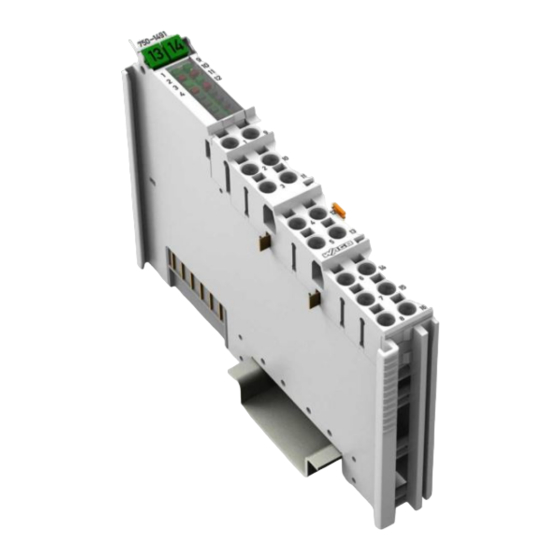
WAGO I/O System 750 Device Description 750-1491 2AI Resistor Bridge (Strain Gauge) View Figure 1: View Table 4: Legend for Figure “View” Pos. Description Details See Section Marking possibility with Mini- Status LEDs “Device Description” > “Display Elements” Data contacts “Device Description”... -
Page 22: Connectors
Device Description WAGO I/O System 750 750-1491 2AI Resistor Bridge (Strain Gauge) Connectors 3.2.1 Data Contacts/Local Bus Communication between the fieldbus coupler/controller and the I/O modules as well as the system supply of the I/O modules is carried out via the local bus. The contacting for the local bus consists of 6 data contacts, which are available as self-cleaning gold spring contacts. -
Page 23: Power Jumper Contacts/Field Supply
WAGO I/O System 750 Device Description 750-1491 2AI Resistor Bridge (Strain Gauge) 3.2.2 Power Jumper Contacts/Field Supply Risk of injury due to sharp-edged blade contacts! The blade contacts are sharp-edged. Handle the I/O module carefully to prevent injury. Do not touch the blade contacts. - Page 24 Device Description WAGO I/O System 750 750-1491 2AI Resistor Bridge (Strain Gauge) Use supply modules for ground (earth)! The I/O module has no power jumper contacts for receiving and transmitting the earth potential. Use a supply module when an earth potential is needed for the subsequent I/O modules.
-
Page 25: Push-In Cage Clamp ® Connectors
WAGO I/O System 750 Device Description 750-1491 2AI Resistor Bridge (Strain Gauge) 3.2.3 Push-in CAGE CLAMP ® Connectors Figure 4: Push-in CAGE CLAMP ® Connectors Table 6: Legend for Figure “Push-in CAGE CLAMP ® Connectors” Channel Designation Connector Function Differential measurement input; bridge voltage (+), channel 1 Differential measurement input;... -
Page 26: Display Elements
I/O module can be achieved even in the presence of interference acting on the signal cable. Shield Connection System for Electromagnetic Compatibility! The WAGO Shield Connection System offers a full range of accessories for maintaining electromagnetic compatibility (EMC)! Related information is available at www.wago.com. -
Page 27: Schematic Diagram
WAGO I/O System 750 Device Description 750-1491 2AI Resistor Bridge (Strain Gauge) Schematic Diagram Figure 6: Schematic Diagram Manual Version 1.0.0... -
Page 28: Technical Data
Device Description WAGO I/O System 750 750-1491 2AI Resistor Bridge (Strain Gauge) Technical Data Table 8: Technical Data Width 12 mm Height 69 mm Depth 100 mm Weight 50 g Number of analog inputs 2 × 2, differential Supply voltage (system) 5 VDC, via data contacts Power consumption –... -
Page 29: Connection Type
WAGO I/O System 750 Device Description 750-1491 2AI Resistor Bridge (Strain Gauge) 3.5.1 Connection Type Table 9: Technical Data ‒ Field Wiring Wire connection Push-in CAGE CLAMP ® Cross section, solid wire 0.08 mm² … 1.5 mm² / AWG 28 … 16 Cross section, fine-stranded wire 0.25 mm²... -
Page 30: Approvals
Approvals More information about approvals. Detailed references to the approvals are listed in the document “Overview on WAGO I/O System 750 approvals”, which you can find via the internet under: www.wago.com DOWNLOADS Documentation System Description. Conformity Marking... -
Page 31: Standards And Guidelines
WAGO I/O System 750 Device Description 750-1491 2AI Resistor Bridge (Strain Gauge) Standards and Guidelines 750-1491 I/O modules meet the following standards and guidelines: EMV Directive 2014/30/EU EMV CE Immunity to interference EN 61000-6-2 EMV CE Emission of interference EN 61000-6-3 Manual Version 1.0.0... -
Page 32: Process Image
2 to 1. In this setting, only 2 instead of 4 inputs are available. The required settings can be made through parameterization with the WAGO-I/O-CHECK commissioning tool. Alternatively, the I/O module can also be parameterized via PROFIBUS and PROFINET device description (GSD file). -
Page 33: Table 13: Process Image ("Standard")
WAGO I/O System 750 Process Image 750-1491 2AI Resistor Bridge (Strain Gauge) Table 13: Process Image (“Standard”) Process Image Input Byte 0 Process value I1_D0 Byte 1 Process value I1_D1 Byte 2 Process value I2_D0 Byte 3 Process value I2_D1... -
Page 34: Control And Status Byte
Process Image WAGO I/O System 750 750-1491 2AI Resistor Bridge (Strain Gauge) Table 15: Process Image (“Standard”) in 1-Channel Mode Process Image Input Byte 0 Process value I1_D0 Byte 1 Process value I1_D1 Byte 2 Process value I2_D0 Byte 3... -
Page 35: Table 18: Status Byte
WAGO I/O System 750 Process Image 750-1491 2AI Resistor Bridge (Strain Gauge) Table 18: Status Byte Status Byte Bit 7 Bit 6 Bit 5 Bit 4 Bit 3 Bit 2 Bit 1 Bit 0 User User General Over- Under- RegCom... -
Page 36: Process Data
Process Image WAGO I/O System 750 750-1491 2AI Resistor Bridge (Strain Gauge) 4.2.1 Process Data 4.2.2 Overview of Signal Voltages The following table provides an overview of all supported signal voltages. The following sections contain detailed information about the individual signal voltages. -
Page 37: Conversion Of The Process Values
WAGO I/O System 750 Process Image 750-1491 2AI Resistor Bridge (Strain Gauge) 4.2.3 Conversion of the Process Values Figure 7: Calculation Process – Process Value to Measured Value This yields the following formulas for converting the local bus process value to the measured value: ����... -
Page 38: Resistor Bridge (Strain Gauge)
Process Image WAGO I/O System 750 750-1491 2AI Resistor Bridge (Strain Gauge) 4.2.4 Resistor Bridge (Strain Gauge) For Strain Gauge (SG) measurements, the I/O module outputs the measured values as a process value standardized to 25000. Example: The defined measuring range of −15 mV ... +15 mV corresponds to a possible process value of −25000 ... +25000. -
Page 39: Sg Bridge Voltage U (±15 Mv)
WAGO I/O System 750 Process Image 750-1491 2AI Resistor Bridge (Strain Gauge) 4.2.5 SG Bridge Voltage U (±15 mV) Table 20: SG Bridge Voltage Settings U (±15 mV) Numeric Value Status Error Voltage [mV] Byte Range Binary Hex. Dec. Hex. -
Page 40: Sg Bridge Voltage U (±60 Mv)
Process Image WAGO I/O System 750 750-1491 2AI Resistor Bridge (Strain Gauge) 4.2.7 SG Bridge Voltage U (±60 mV) Table 22: SG Bridge Voltage Settings U (±60 mV) Numeric Value Status Error Voltage [mV] Byte Range Binary Hex. Dec. Hex. -
Page 41: Sg Bridge Voltage U (±240 Mv)
WAGO I/O System 750 Process Image 750-1491 2AI Resistor Bridge (Strain Gauge) 4.2.9 SG Bridge Voltage U (±240 mV) Table 24: SG Bridge Voltage Settings U (±240 mV) Numeric Value Status Error Voltage [mV] Byte Range Binary Hex. Dec. Hex. -
Page 42: Sg Reference Voltage U
Process Image WAGO I/O System 750 750-1491 2AI Resistor Bridge (Strain Gauge) 4.2.11 SG Reference Voltage U (+5 V internal) Table 26: SG Reference Voltage Settings U (+5 V, internal) Numeric Value Status Error Voltage [mV] Byte Range Binary Hex. -
Page 43: Ref (±10 V External)
WAGO I/O System 750 Process Image 750-1491 2AI Resistor Bridge (Strain Gauge) 4.2.13 SG Reference Voltage U (±10 V external) Table 28: SG Reference Voltage Settings U (±10 V, external) Numeric Value Status Error Voltage [mV] Byte Range Binary Hex. -
Page 44: Mounting
Mounting WAGO I/O System 750 750-1491 2AI Resistor Bridge (Strain Gauge) Mounting Do not work when devices are energized! High voltage can cause electric shock or burns. Switch off all power to the device prior to performing any installation, repair or maintenance work. -
Page 45: Mounting Sequence
Always plug a bus end module (750-600) onto the end of the fieldbus node! You must always use a bus end module at all fieldbus nodes with WAGO I/O System 750 fieldbus couplers or controllers to guarantee proper data transfer. -
Page 46: Inserting And Removing Devices
Mounting WAGO I/O System 750 750-1491 2AI Resistor Bridge (Strain Gauge) Inserting and Removing Devices 5.2.1 Inserting the I/O Module Position the I/O module in such a way that the groove and spring are connected to the preceding and following components. -
Page 47: Removing The I/O Module
WAGO I/O System 750 Mounting 750-1491 2AI Resistor Bridge (Strain Gauge) Once the I/O module has snapped into place, the electrical connections for the data contacts and power contacts (if any) to the head station or to the preceding and, if applicable, following I/O module are established. -
Page 48: Connect Devices
Do not connect more than one conductor at one single connection! If more than one conductor must be routed to one connection, these must be connected in an up-circuit wiring assembly, for example using WAGO feed- through terminals. Terminate both solid and stranded or ferruled conductors by simply pushing them in - no tool required. -
Page 49: Figure 11: Connecting A Conductor To A Push-In Cage Clamp
WAGO I/O System 750 Connect Devices 750-1491 2AI Resistor Bridge (Strain Gauge) Figure 11: Connecting a Conductor to a Push-in CAGE CLAMP ® Manual Version 1.0.0... -
Page 50: Connection Examples
The I/O module (2AI Resistor Bridge (Strain Gauge)) has very sensitive measurement inputs. Disable unused inputs to avoid unwanted error messages. Section “Configuration and Parameterization with WAGO-IO-CHECK” describes how one input, or the diagnostics of individual inputs, of the I/O module can be switched on/off. -
Page 51: 4-Wire Operation (Internal Supply)
Connect Devices 750-1491 2AI Resistor Bridge (Strain Gauge) 6.2.2 4-Wire Operation (Internal Supply) Use WAGO Through Terminal Blocks! As in this example, if two conductors are to routed to CAGE CLAMP connection, ® they must be connected in an up-circuit wiring assembly. -
Page 52: Calibration
Connect Devices WAGO I/O System 750 750-1491 2AI Resistor Bridge (Strain Gauge) 6.2.4 Calibration 6.2.4.1 Connection Examples with External Power Supply Figure 15: Wiring Examples for Calibration of the Bridge Voltage U (External Power Supply) Figure 16: Wiring Examples for Calibration of the Reference Voltage U... -
Page 53: Connection Examples With Internal Power Supply
WAGO I/O System 750 Connect Devices 750-1491 2AI Resistor Bridge (Strain Gauge) 6.2.4.2 Connection Examples with Internal Power Supply Figure 17: Wiring Examples for Calibration of the Bridge Voltage U (Internal Power Supply) Figure18: Wiring Examples for Calibration of the Reference Voltage U... -
Page 54: Commissioning
Commissioning WAGO I/O System 750 750-1491 2AI Resistor Bridge (Strain Gauge) Commissioning The following actions can be performed: • Read out module information • Configure inputs • Calibrate inputs • Scale inputs (see also Section “Scaling Measured Values”) • Read out diagnostic information •... -
Page 55: Tooling
WAGO I/O System 750 Commissioning 750-1491 2AI Resistor Bridge (Strain Gauge) Tooling The following matrix specifies which tool can be used to make settings on the I/O module: Table 30: Settings Using Tools Settings e!COCKPIT WAGO-I/O-CHECK PB-GSD PN-GSD Channels ×... -
Page 56: Configuration And Parameterization With Wago-I/O-Check
Calibration of channels and adjustment of analog inputs • Monitoring WAGO-I/O-CHECK You can obtain the WAGO-I/O-CHECK software on a CD under Item No. 759-302. This CD contains all the application program files and an explanation. You can find a description on the website at www.wago.com... -
Page 57: Figure 19: Wago-I/O-Check User Interface (Example)
Commissioning 750-1491 2AI Resistor Bridge (Strain Gauge) Figure 19: WAGO-I/O-CHECK User Interface (Example) After the node structure has been identified in WAGO-I/O-CHECK, it appears in the overview area. To open specific parameterization dialogs for the 750-1491 I/O Module, proceed as follows: Select the I/O module. -
Page 58: Parameterization Dialog
Commissioning WAGO I/O System 750 750-1491 2AI Resistor Bridge (Strain Gauge) 7.3.1 Parameterization Dialog The parameterization dialog is divided into the following areas: Figure 20: I/O Module Parameterization Dialog Title bar with the position and indication of the selected I/O module... -
Page 59: Information Bar
WAGO I/O System 750 Commissioning 750-1491 2AI Resistor Bridge (Strain Gauge) 7.3.1.2 Information Bar • Item number: 750-1491 • Item description: 2AI Resistor Bridge (Strain Gauge) • Version: 01.01.xx(xx) 7.3.1.3 Buttons Table 31: Buttons Button Function Explanation Closes the parameterization dialog. -
Page 60: Menu
Commissioning WAGO I/O System 750 750-1491 2AI Resistor Bridge (Strain Gauge) 7.3.1.4 Menu Via the menu items, select the application area view. When a menu item is selected, the associated parameters are displayed in the application area: Table 32: Navigation via the Menu... -
Page 61: Common
WAGO I/O System 750 Commissioning 750-1491 2AI Resistor Bridge (Strain Gauge) 7.3.2.1 Common Via the [Common] menu item, the following I/O parameters can be set: Table 33: “Common” Menu Item Parameter Settings / Description Interference The input filter is used to suppress interfering mains frequency frequency signal components. -
Page 62: Input Settings
Commissioning WAGO I/O System 750 750-1491 2AI Resistor Bridge (Strain Gauge) Table 33: “Common” Menu Item Parameter Settings / Description Process image In the standard process image, the control/status byte is hidden by the head Standard station and is therefore not visible in the fieldbus process image. -
Page 63: Figure 22: Menu Item "Input U
WAGO I/O System 750 Commissioning 750-1491 2AI Resistor Bridge (Strain Gauge) Figure 22: Menu Item “Input U x” (Example “U 1”) Figure 23: Menu Item “Input U x” (Example “U 1”) Manual Version 1.0.0... -
Page 64: Table 34: "Menu Items "Input X
Commissioning WAGO I/O System 750 750-1491 2AI Resistor Bridge (Strain Gauge) Table 34: “Menu Items “Input X” Parameter Setting Option / Description Bridge voltage This parameter can be used to set the measuring range of the bridge voltage or deactivate the input. -
Page 65: Scaling
WAGO I/O System 750 Commissioning 750-1491 2AI Resistor Bridge (Strain Gauge) Table 34: “Menu Items “Input X” Parameter Setting Option / Description Diagnosis: This parameter can be used to switch diagnostics on/off for Measuring range a measuring range overflow. overflow Measuring range overflow diagnosis is switched off. - Page 66 Commissioning WAGO I/O System 750 750-1491 2AI Resistor Bridge (Strain Gauge) Checking/unchecking the box has an immediate effect! When the box is checked, the setting is written immediately to the I/O module; it is not necessary to click the [Write] button.
-
Page 67: Figure 25: "Scaling" Menu Item
WAGO I/O System 750 Commissioning 750-1491 2AI Resistor Bridge (Strain Gauge) Figure 25: “Scaling” Menu Item (Example “Input U 1”) Table 35: “Scaling” Menu Item Parameter Setting Option / Description Manufacturer The gain and offset values of the manufacturer scaling are scaling displayed and cannot be changed. -
Page 68: Calibration
Commissioning WAGO I/O System 750 750-1491 2AI Resistor Bridge (Strain Gauge) Table 35: “Scaling” Menu Item Parameter Setting Option / Description Show values in The hexadecimal representation can be switched on or off. hexadecimal Hexadecimal representation is enabled. The values are displayed as fixed-point ... -
Page 69: Figure 26: "Calibration" Menu Item
WAGO I/O System 750 Commissioning 750-1491 2AI Resistor Bridge (Strain Gauge) Figure 26: “Calibration” Menu Item (Example “Input U 1”) Figure 27: “Calibration” Menu Item (Example “Input U 1”) Manual Version 1.0.0... -
Page 70: Table 36: "Calibration" Menu Item
Commissioning WAGO I/O System 750 750-1491 2AI Resistor Bridge (Strain Gauge) Table 36: “Calibration” Menu Item Parameter / Button Setting Option / Description [Start Calibration] Pressing this button starts an automatic assistant with which the entire measuring section can be adjusted to the local conditions. -
Page 71: Figure 28: "User Calibration" Dialog - Offset Correction
WAGO I/O System 750 Commissioning 750-1491 2AI Resistor Bridge (Strain Gauge) Figure 28: “User Calibration” Dialog – Offset Correction Figure 29: “User Calibration” Dialog – Gain Correction Manual Version 1.0.0... - Page 72 Commissioning WAGO I/O System 750 750-1491 2AI Resistor Bridge (Strain Gauge) For offset and gain correction, arbitrary reference values within the measurement range can be entered as setpoints. Ideally, the reference values should be as close as possible to the lower (offset correction) or upper (gain correction) full scale value.
-
Page 73: Configuration And Parameterization With E!Cockpit
Behavior after Overwriting with WAGO-I/O-CHECK ! If WAGO-I/O-CHECK is used to overwrite a parameterization made with the GSD file, the I/O module operates with the WAGO-I/O-CHECK settings until the PROFIBUS/PROFINET Couplers are restarted. After restart, the I/O module is re-parameterized via PROFIBUS/PROFINET using the GSD settings. -
Page 74: Profinet Io Fieldbus Couplers 750-375(/025-000), 750-377(/025-000)
Commissioning WAGO I/O System 750 750-1491 2AI Resistor Bridge (Strain Gauge) 7.5.1.2 PROFINET IO Fieldbus Couplers 750-375(/025-000), 750-377(/025-000) When the aforementioned PROFINET IO fieldbus couplers are used, the process image size is configured by selecting the corresponding GSD entry. Table 38: PROFINET IO Configuration PA Length/ Inst. -
Page 75: Profinet Io Fieldbus Couplers 750-375(/025-000), 750-377(/025-000)
WAGO I/O System 750 Commissioning 750-1491 2AI Resistor Bridge (Strain Gauge) 7.5.2.2 PROFINET IO Fieldbus Couplers 750-375(/025-000), 750-377(/025-000) On the PROFINET IO fieldbus couplers, the I/O module can be provided with operating parameters using the PROFINET GSD file under the category “Specific Module/Channel Parameters”. -
Page 76: All Profibus Dp And Profinet Io Fieldbus Couplers
All PROFIBUS DP and PROFINET IO Fieldbus Couplers The following association applies to the parameters of the I/O module in connection with the use of WAGO-I/O-CHECK as well when using PROFIBUS DP and PROFINET IO fieldbus devices. Device-Specific Parameters” or “Specific Module/Channel Parameters”... -
Page 77: Profinet Io Fieldbus Couplers 750-375(/025-000), 750-377(/025-000)
-32768 … 16384 … Gain -2.0000 … 1.0000 x, U x (x = 1, 2)] 32767 [Input U x, U x (x = 1, 2)] … 1.9999 Factory setting The resolution of 1/16384 is already included in WAGO-I/O-CHECK. Manual Version 1.0.0... -
Page 78: Scaling Measured Values
Scaling Measured Values WAGO I/O System 750 750-1491 2AI Resistor Bridge (Strain Gauge) Scaling Measured Values User scaling serves to adjust the process values. When user scaling is used, the required accuracy of the process value resolution is changed, but not fundamentally limited. -
Page 79: Calibrating Measured Values
Use the connection type “4-Wire Mode (External Power Supply)” for the calibration. For the I/O module, WAGO offers the option of performing the calibration using the WAGO-I/O-CHECK calibration dialog. To calibrate the I/O module, proceed as follows: Connect a measuring bridge (or a comparable resistor network) directly to the I/O module. -
Page 80: Figure 32: Calibration Of The Bridge Voltage U
Figure 32: Calibration of the Bridge Voltage U when Operating with an External Power Supply (Example for Channel 1) Use WAGO-I/O-CHECK to calibrate the equipment via this calibrator. Remove the calibrator. To calibrate the reference voltage Uref (Input 2), connect a calibrator directly to the measuring bridge (see connection example in Figure “Calibration of the Reference Voltage U... - Page 81 750-1491 2AI Resistor Bridge (Strain Gauge) Figure 33: Calibration of the Reference Voltage U when Operating with an External Power Supply (Example for Channel 1) Use WAGO-I/O-CHECK to calibrate the equipment via this calibrator. Remove the calibrator. Proceed accordingly for channel 2. Manual...
-
Page 82: Calibration When Operating With An Internal Power Supply
Figure 34: Calibration of the Bridge Voltage U when Operating with an Internal Power Supply (Example for Channel 1) Use WAGO-I/O-CHECK to calibrate the equipment via this calibrator. Remove the calibrator. To calibrate the reference voltage U (Input 2), connect a calibrator directly to the measuring bridge (see connection example in Figure “Calibration of... -
Page 83: Figure 33: Calibration Of The Reference Voltage U
Figure 35: Calibration of the Reference Voltage U when Operating with an Internal Power Supply (Example for Channel 1) Use WAGO-I/O-CHECK to calibrate the equipment via this calibrator. Remove the calibrator. Restore the connection to the previously disconnected +U line. -
Page 84: Diagnostics
The behavior of the I/O module if a diagnosis is present depends on whether the various parameters for monitoring are switched on or off. You can activate or deactivate these diagnostics separately in WAGO-I/O- CHECK (see Section “Commissioning” > … > “Parameterization with WAGO-I/O- CHECK”). -
Page 85: Table 44: Behavior Of The I/O Module In The Event Of Overflow/Underflow
WAGO I/O System 750 Diagnostics 750-1491 2AI Resistor Bridge (Strain Gauge) Table 44: Behavior of the I/O Module in the Event of Overflow/Underflow Overflow/ Underrange/ Behavior of the I/O Module in the Event Underflow Overrange of Overflow/Underflow Monitoring Monitoring •... -
Page 86: Table 45: Behavior Of The I/O Module In The Event Of Range Violation
Diagnostics WAGO I/O System 750 750-1491 2AI Resistor Bridge (Strain Gauge) Table 45: Behavior of the I/O Module in the Event of Range Violation Overflow/ Underrange/ Behavior of the I/O Module in the Event Underflow Overrange of Range Violation Monitoring Monitoring •... -
Page 87: Diagnostics Via Led Indicators
WAGO I/O System 750 Diagnostics 750-1491 2AI Resistor Bridge (Strain Gauge) No monitoring of the 24 V field voltage! A diagnosis of “Field voltage too low / not available” is not possible. 10.2 Diagnostics via LED Indicators The indicators of the I/O module provide information about possible states and cases of error. - Page 88 Diagnostics WAGO I/O System 750 750-1491 2AI Resistor Bridge (Strain Gauge) Table 49: Signal Evaluation for Each Input – “Error U X” (LED 10 or 12) Error LED State Possible Interpretation No error Input deactivated Diagnostics deactivated Underflow Overflow Measurement underrange...
-
Page 89: Use In Hazardous Environments
Use in Hazardous Environments 750-1491 2AI Resistor Bridge (Strain Gauge) Use in Hazardous Environments The WAGO I/O SYSTEM 750 (electrical equipment) is designed for use in Zone 2 hazardous areas and shall be used in accordance with the marking and installation regulations. -
Page 90: Marking Configuration Examples
Use in Hazardous Environments WAGO I/O System 750 750-1491 2AI Resistor Bridge (Strain Gauge) 11.1 Marking Configuration Examples 11.1.1 Marking for Europe According to ATEX and IECEx Figure 36: Marking Example per ATEX and IECEx Figure 37: Text Detail – Marking Example per ATEX and IECEx Manual Version 1.0.0... -
Page 91: Table 50: Description Of The Marking Example Per Atex And Iecex
WAGO I/O System 750 Use in Hazardous Environments 750-1491 2AI Resistor Bridge (Strain Gauge) Table 50: Description of the Marking Example per ATEX and IECEx Marking Text Description TUEV 07 ATEX 554086 X Approving authority or certificate numbers IECEx TUN 09.0001 X... -
Page 92: Figure 38: Marking Example Of An Approved I/O Module Ex I Per Atex And
Use in Hazardous Environments WAGO I/O System 750 750-1491 2AI Resistor Bridge (Strain Gauge) Figure 38: Marking Example of an Approved I/O Module Ex i per ATEX and IECEx Figure 39: Text Detail – Marking Example of an Approved I/O Module Ex i... -
Page 93: Table 51: Description Of The Marking Example Of An Approved I/O Module Ex I Per Atex And Iecex
WAGO I/O System 750 Use in Hazardous Environments 750-1491 2AI Resistor Bridge (Strain Gauge) Table 51: Description of the Marking Example of an Approved I/O Module Ex i per ATEX and IECEx Marking Text Description TUEV 12 ATEX 106032 X... -
Page 94: Marking For The United States Of America (Nec) And Canada (Cec)
Use in Hazardous Environments WAGO I/O System 750 750-1491 2AI Resistor Bridge (Strain Gauge) 11.1.2 Marking for the United States of America (NEC) and Canada (CEC) Figure 40: Marking Example According to NEC Figure 41: Text Detail – Marking Example According to NEC 500... -
Page 95: Figure 42: Text Detail - Marking Example For Approved I/O Module Ex I
WAGO I/O System 750 Use in Hazardous Environments 750-1491 2AI Resistor Bridge (Strain Gauge) Figure 42: Text Detail – Marking Example for Approved I/O Module Ex i According to NEC 505 Table 53: Description of Marking Example for Approved I/O Module Ex i According to NEC 505... -
Page 96: Figure 44: Text Detail - Marking Example For Approved I/O Module Ex I
Use in Hazardous Environments WAGO I/O System 750 750-1491 2AI Resistor Bridge (Strain Gauge) Figure 44: Text Detail – Marking Example for Approved I/O Module Ex i According to CEC 18 attachment J Table 55: Description of Marking Example for Approved I/O Module Ex i According to CEC 18... -
Page 97: Installation Regulations
Special Notes including Explosion Protection The following warning notices are to be posted in the immediately proximity of the WAGO I/O SYSTEM 750 (hereinafter “product”): WARNING – DO NOT REMOVE OR REPLACE FUSED WHILE ENERGIZED! WARNING – DO NOT DISCONNECT WHILE ENERGIZED! WARNING –... - Page 98 Use in Hazardous Environments WAGO I/O System 750 750-1491 2AI Resistor Bridge (Strain Gauge) Explosive atmosphere occurring simultaneously with assembly, installation or repair work must be ruled out. Among other things, these include the following activities • Insertion and removal of components •...
-
Page 99: Special Notes Regarding Ul Hazardous Location
WAGO I/O System 750 Use in Hazardous Environments 750-1491 2AI Resistor Bridge (Strain Gauge) 11.2.2 Special Notes Regarding UL Hazardous Location For UL Hazardous Location acc. to UL File E198726, the following additional requirements apply: • Use in Class I, Division 2, Group A, B, C, D or non-hazardous areas only •... -
Page 100: Service
Wait 30 seconds before continuing to operate the I/O module! 12.2 Firmware Update/Downgrade You can update firmware on the Series 750 I/O Modules with the software “WAGO I/O-Update 750.” The I/O modules can be updated via the service Manual Version 1.0.0... - Page 101 Only run the software from a local hard disk. Additional Information from WAGO Support! Additional information about the software “WAGO I/O-Update 750” is available through WAGO Support. Firmware Downgrade Contact WAGO Support to discuss whether a firmware downgrade is possible in your situation. Manual Version 1.0.0...
-
Page 102: Recalibration
102 Service WAGO I/O System 750 750-1491 2AI Resistor Bridge (Strain Gauge) 12.3 Recalibration Calibrating the I/O module may provide the process value accuracy required by the application. It may be necessary to perform a recalibration in order to maintain the accuracy despite aging of individual components of the line. -
Page 103: Wago Uii (Unique Item Identifier)
750-1491 2AI Resistor Bridge (Strain Gauge) 12.4 WAGO UII (Unique Item Identifier) Each I/O module (750-1491) is provided with a unique WAGO UII (“Unique Item Identifier”). Application example: The I/O module can be permanently assigned a calibration certificate via this UII. -
Page 104: List Of Figures
(Internal Power Supply) ................53 Figure18: Wiring Examples for Calibration of the Reference Voltage U (Internal Power Supply) ................53 Figure 19: WAGO-I/O-CHECK User Interface (Example) ........57 Figure 20: I/O Module Parameterization Dialog ..........58 Figure 21: “Common” Menu Item ...............60 Figure 22: Menu Item “Input U x”... - Page 105 WAGO I/O System 750 List of Figures 105 750-1491 2AI Resistor Bridge (Strain Gauge) Figure 38: Marking Example of an Approved I/O Module Ex i per ATEX and IECEx......................92 Figure 39: Text Detail – Marking Example of an Approved I/O Module Ex i per ATEX and IECEx ................92...
-
Page 106: List Of Tables
106 List of Tables WAGO I/O System 750 750-1491 2AI Resistor Bridge (Strain Gauge) List of Tables Table 1: Number Notation ..................10 Table 2: Font Conventions .................10 Table 3: Compatibility List 750-1491 ..............19 Table 4: Legend for Figure “View” ..............21 Table 5: Legend for Figure “Power Jumper Contacts”... - Page 107 WAGO I/O System 750 List of Tables 107 750-1491 2AI Resistor Bridge (Strain Gauge) Tabelle 47: Signal Evaluation for Each Input – “Function U X” (LED 9 or 11) ...87 Table 48: Signal Evaluation for Each Input – “Error U X”...
- Page 108 WAGO Kontakttechnik GmbH & Co. KG Postfach 2880 • D - 32385 Minden Hansastraße 27 • D - 32423 Minden Phone: +49 571 887 – 0 Fax: +49 571 887 – 844169 E-Mail: info@wago.com Internet: www.wago.com...
Need help?
Do you have a question about the 750 Series and is the answer not in the manual?
Questions and answers